Transcription
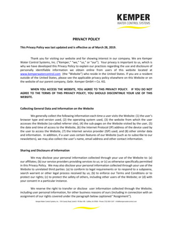
Installation and Operation ManualKEMPER system 9000Extraction and filter unit with automatic filtercleaningRef. 90 0757.500 m³/h
Table of ContentsA.Application and OperationB.Safety InformationC.Control panel and self diagnostic control systemC-1 Putting Filter unit into operationC-2 Message and information of control deviceC-3 System Information and malfunctionD.MaintenanceD-1 Emptying of dust collecting containerD-2 Drain condensateD-3 Tensioning of belt-driveD-4 Tensioning the belt-drive / lubrication of bearingE.Technical specifications and data-sheetF.Spare part listG.EC declaration of conformityH.Wiring diagrammAdress list
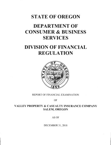
A.Application and OperationKEMPER Cartridge filters are mainly used for the extraction and filtering of weldingsmoke, dust and harmful substances created during the process of plasma and flamecutting operations. To capture all these harmful substances the following capture devicesare used: Exhaust hoodsDown-draft tablesExhaust arms and cranesSuction nozzlesetc.Via these capturing devices, the polluted air is led into the filter unit through a duct system.Through the air circulation coarse particles are seperated in the first section.The seperation of the polluted air works according to the principle of surface filtration bymeans of cartridges with Teflonmembrane.This membrane has a very homogeneous pore structure and is permeable to air However,it retains even the smallest particles. Thus the welding smoke is separated at the surfaceof the filter cartridges. The cleaned air flows up wards inside the filter cartridges andreaches the clean air section of the filter unit. From there it is led to the ventilator and thenback to the workroom or via a duct system to atmosphere.Due to the contineous settling of particles on the surface a resistance is set up. Once theallowed air resistance is reached the cleaning process starts automatically. This is donethrough rotating nozzles by means of compressed air. The compressed air reservoir isinstalled in the filter aggregate. Through the rotating nozzles the compressed air worksfrom the inside on the whole surface of the respective filter cartridge.The filter cartridges are cleaned individually in turn. Thus permanent running isguaranteed during cleaning Further more, every time the machine is switched off thedescribed cleaning process starts automatically.After the seperated dust has been blown off the cartridges it falls down to the collectingbox which is mounted underneath the cartridges. To remove the collecting container it canbe lowered very easy by using the compresser air lift.All main functions of the unit are permanently controlled by the electronic control system.The display gives information of Filters, Motors, Airflow and working hours etc. Also ithelps to find and avoid possible malfunctions.All information is automatically shown on the cleartext display.
B.Safety Information*Caution:When using electrical devices the following basic safety measuresmust be followed to prevent shock, injury or fire!Read and follow these instructions carefully before using the filter unit!*Keep this Installation and Operation Manual handy.*Read data on Typeplate*Before opening the maintanance door switch off the machine.*Don't use this Filter unit for the extraction of flamable or explosivesubstances (e.g. solvents).*Don't use this Filter unit for the extraction of explosive dusts(e.g. aluminium powder).*Don't use this Filter unit for the extraction of aggressive substances (e.g. acids).*Don't use the Filter unit without Filter inserts.*Always use original spare parts.*Keep the machine dry.*Connect the machine to power only by authorized electrician.*Check direction of rotation of the ventilator
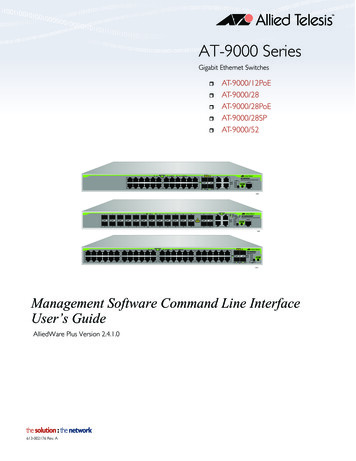
C.Control panel and selfdiagnostic systemC-1 Putting filter unit into operation1 Cleartext display2 On/Off switchTo switch the machine on and off.3 SERVICE switchShows how many working hours are left before the next service.4 ADDRESS switchShows the adress of the manufacturer (and telephone, telefax and website).5 Conformation switchConfirmation switch (for service)6 SHIFT switchNot needed for normal use of the unit.7 ESC switchNot needed for normal use of the unit.8 ENTER switchConfirmation switch9 Scroll switchTo scroll messages on the display
C-2 Messages and information of control deviceBy use of the control unit with cleartext display the settings and parameters of theunit can be changed or called up. All readings and functions are described below.M A C HIIN E/ 0O P E R A T I N GS W I T C HBYAs soon as the unit is connected to the power and switched on by the main-switch(main switch only at series 9000 units) the display shows this message. Now theunit can be started by using the on/off switch and switched off as well. If the unit isnot used for a longer period eg. on weekends, we recommend not to use themain-switch (series 9000) and to keep the machine off-line. Even if the machineis in an off-line modus an after cleaning cycle is started.M A C H I N EO P E R A T I N GE X T E R N A LS W I T C HBYAs an option the unit can be switched on and off via an external on/off switch or apotentional free contact. (For example welding robots, cutting machines etc.) If theunit is equipped with this option and was started by the on/off switch the abovemessage will be shown on the display. As soon as the external switch is connectedto the unit it will start up automatically.Programme PointY O U RK E M P E RS Y S T EO P E R A T E SC O R R E C T LMYAfter the machine has been switched on, this message will come up on thedisplay. The control unit will always return to this message from other programmepoints after approx 3 min. Any operation fault which appear will be shownautomatically . By using the scroll function you can get to other programme points.Programme Point 10 1W O R K . H R S .C L E A N I N G::0 0 00 0 0000000Indicates the total working hours of the machine regarding the operating time ofthe ventilator and the number of completed cleaning cycles. The number ofcleaning cycles indicates the actual cleaning cycles that have been undertakenduring operation and also after cleaning cycles after switching of the unit.
Programme Point 20 2C A R T RT O T A LID G E:FI L T E R0This indicates the number of filter cartridges installed.„SERVICE“ – switchN E X TS E R VIC EIN:1 6 0 0H R SThis KEMPER filter unit is a unit with vital function and may only be operatedunit regarding to certain aspects of reliability. It is regulated by law that the unithas to be checked regularly and necessary maintenance work has to beundertaken. The frequency of maintenance works is depending on the workinghours of the unit. This reading indicates how many working hours are left untilthe next service should be carried out. By pressing the service button again youwill get back to the start display.„ADDRESS“ – switchK E M P E RV E N T U R E( U . K . ) L T DC O U R TBy pressing this button you are able to read the complete manufactureraddress.By using the scroll function the display scrolls down to telephone, telefax,website and the following message:S O F T W . VM A C H . N R.:0 0 0/B J:Indicates which software version was used, when the machine was built, theyear of construction and month of delivery and serial number of the machine. Ifa visit of a service technican is required please pass on the information of thatreading to our service department, they can identify the unit by theseinformation.
C.3 System information and malfunctionDuring operation the standard reading will change to the following if there aremalfunctions.MaintenanceS E R VIC EN E C E S S A R Y0 0 0 0H R SWith this reading the machine informs the user about an overdue service, whichis also regulated by law. Please contact Kemper to make an appointment for theservice to be undertaken (contact details see button „Address“). By pressing the„Enter“-Button this reading can be confirmed. The reading will come up aftershort time. The filter unit will work correctly during this time.MaintenanceS E R V I C ES I N C E:O V E R D U E0 0 0 0 0H R SWith this message indicates that the overdue maintenance has not beenundertaken, yet. This maintenance is regulated by law and essential for theoperational safety of the machine. The maintenance should be undertakendirectly by our KEMPER service engineers.
Malfunction 1E-0 1M O T O RP R O T E C TI O NF A NThis reading informs about a malfunction of the motor protection switch of thefan due to excessive power supply resulting our of changes in voltage or faultsin the motor. If the motor potection switch is tripped out, please check if all 3phases are connected. Please contact Kemper to check the unit if this readingappears again.Malfunction 3E-0 3M O T O R T E M P E R A TT O OH I G HAn optional accessory are temperature sensors in the motor. If the motor isgetting too warm the machine switches off automatically and the above readingappears. The motor temperature of the machine is too high and the unit hasbeen switched of because of security aspects. Please contact KEMPER(contact details see button „Adress“).Malfunction 4E-0 4D U S TC O L L E C T O RO P E NThe dust collecting container will be lifted upwards to seal the container. If thisreading appears the dust collecting container is lifted down. The unit can not beoperated in this case and will be switched off or can not be switched on. Lift thecontainer by shifting the hand valve.Malfunction 5E-0 5C O N T A C T O RI N C O R R E C TO P E R.The unit controls also the function of the main motor protection switch and thestar or delta switch. Appears the above described malfunction, please contactan electrician or the KEMPER service department (contact details see button„Address“).
D.MaintenanceD-1. Emptying of the dust collecting containerThe dust collecting container should be emptied regulary. The intervals should bespecified with respect to the amount of dust created by the process. If very light dustsare created the intervals should be shorter.To discharge the dust collecting container: Switch off the filter unit by using the main switch Open the maintenance door of the filter unit Lower the collecting container by shifting the pneumatic valve to left hand side.(The pneumatice valve is on the left hand side of the dust collecting container)E -0 4D U S TC O L L E C T I N GC O N T A I N E RO P E NRemove the container from the filter unitPlease note:The collected dust has to be recycled according to public regulations. Put the container back on the pneumatic lift. Lift the container by shifting the pneumatic valve.Please note:Please pay attention that no objects are between sealing of the container and filterunit
The following reading appears in the display:S W IT C H I N GI / 0-O NS W IV I AT C H Close the maintenance door of the filter unit Switch the unit on via the 1/0-switchD-2. Drain of condensateThe condensate should be drained regularly every month. The drain valve is locatednext to the pressure air maintenance unit. Put a suitable container below the drainvalve and open the valve. Close the valve after all moister has been drained and onlyair is puring out of the valve.D-3. Tensioning the belt-driveAfter about 50 working hours the belt-drive of the ventilator needs to be checked andthe tension of the belt should be re-adjusted first time. After that approx. every 3 to 4month the belt drive should be checked. The depth of intendation of the belt betweenboth belt pulleys should be approx. 8 mm at a test force of 11 Newton.Procedure: Switch the unit off by using the main switch. The power supply isdisconnected. Secure the switch with a pad lock. Open the maintenance door of the fan unit. If the beltdrive is to loose you can tension it by moving the complete motorbackwards. The motor is installed on an frame with 4 bolts. Open those boltsand move the motor backwards by using the two adjustment bolts on themotor frame. Close the maintenance door of the fan unit. Switch the machine on by using the main switch.
D-4. Tensioning the belt-drive / lubrication of bearing(only for high vacuum units)After about 50 working hours the belt-drive needs to be checked and the tension ofthe belt should be re-adjusted first time. After that the bearing of the turbine has to belubricated and also the belt-drive has to be checked regularly (Parameters seemaintenance sticker on the turbine).Procedure: Switch the unit off by using the main switch. The power supply isdisconnected. Secure the switch with a pad lock. Open the maintenance door of the fan unit. The maintenance work has to be undertaken according to the instructions onthe maintenance sticker of the turbine. Close the maintenance door of the fan unit. Switch the machine on by using the main switch.
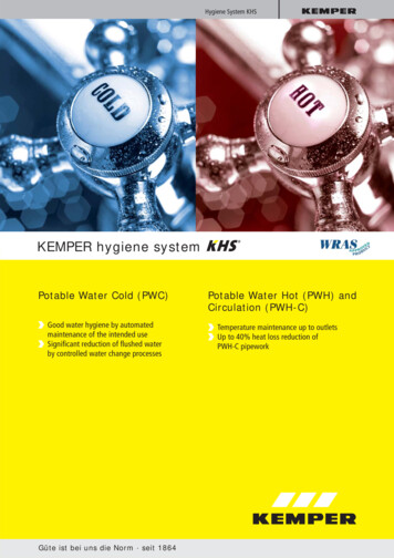
Technical spezification / Data sheetCartidge Filter UnitCustomer :Part. No. 90 075 - 4.410 cfm - 7.500 m³/hTechnical spezification Filter unit :Filter surface :Filter type :Dimensions of each cartrigde :Rotating nozzles :Dimensions of the Filter Unit :Air intake :Air outlet :Commpressed air :Dimension of dust collecting containerWeight :9 cartrigdes each 10 m2 90 m2Filtercartridge with PTFE-Coatingdiam. 327 mm x 600 mmlenght 600 mmW 1.413 mm x D 1.864 mm x H 2.015 mmdiam. 450 mmdiam. 560 mm5,0 – 6,0 bar; clean, dry and free of oil192 ltr.640 kgTechnical spezification Ventilator unit:Fan performance :Ventilator type :Ventilator speed :Motor performance :Power supply :Amperage :Dimensions of the Ventilator Unit :Weight :4.410 cfm or 7.500 m3/h at 3.666 PaCentrifugal fan; RZR 19-03154.664 1/min11 kW / 2.915 1/min3 x 400 V, 50 Hz23 AW 1.413 mm x D 1.864 mm x H 2.015 mm750 kg
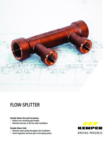
G.Spare Part ListSuction and Filter Unit Type 90075ItemDescriptionPart.No.1Filtercartridge with PTFE MembraneFiltersurface 10 m², incl. gasket109 03002Filtercartridge without MembraneFor applications with high oil mist content,Filtersurface 12 m², incl. gasket109 03013Motor 400/690 Volt – 11,0 kW130 00474Ventilator RZR 19-0315121 02235Rotation nozzle, complete ,without solenoid valve77 600 000 196Solenoid valve 1“, 24 V, AC128 01407Compressed air fabric tube 1“128 00718Hose clamp 1“115 00209Sparefilter set for compressed airmaintenance unit132 001710Motor protection relais118 029711Contactor118 024412Drive belt SPZ 1700(2 pcs. required)117 013113V-belt pulley- Ventilator 2 x SPZ 150117 026914V-belt pulley – Motor 2 x SPZ 200117 019715Dust bin liners, 10 per set119 0139
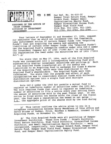
0123456789WUPE002D24.02.1994KEMPER GMBHVon Siemensstraáe 20 - 21Fax.: 0049(0)2564/68-120D-48691 Vredenhttp://www.kemper.deTel.: 0049(0)2564/68-0e-mail: ENTRAL sion:(INSTALLATION NAME)(SCHEMATIC NO.)Hersteller-Firma 1:(MANUFACTURING FIRM 1)KEMPER r-Firma 2::integratedEinspeisung:3 x 400V/AC/50Hz PEZuleitung:4(5) x 6mmý / 21 A (current)Steuerspannung:230V/AC 24V/ACBaujahr:see type plate(SWITCH CABINET)(SUPPLY VOLTAGE)48691 VREDEN(MANUFACTURING FIRM 2)(SUPPLY CABLE)(CONTROL VOLTAGE)Fabrikat:System STALLATION PLACE)(YEAR OF BUILDING)Teilebesonderheit :with Star-Delta art:Pre-Fuse: 3 x 25 A (min. Kat. C)(PART CHARACTERISTIC)(SPECIAL ENVIRONMENT(LOCATION)(RULE)(PROTECTION LEVEL)(PROJECT BEGINNING)Projekt Beginn: 18.Feb.2002Projektverantwortlicher:Letzte Ž nderung: 01.Okt.2003Letzter Bearbeiter: GHK(PROJECT LEADER)(LAST CHANGE)(LAST OFFICIAL)(HIGHEST NO. OF PAGES)H”chste Seitenzahl:12Anzahl der Seiten :12(NO. OF PAGES)2DatumCOVERSHEETBearb. GHKGepr.Ž nderungDatumNameNorm01.Okt.2003CENTRAL SUCTION-UNITUrspr.Ers.f.02-E-504-1-12/390075Ers.d. 1Bl.12Bl.
CONTENTS)5678Spalte X: eine automatisch erzeugte Seite wurde manuell nachbearbeitetSeitenzusatzfeld(NAME OF PAGE)Datum(EXTRA PAGE-FIELD)(DATE)9WUPJ005D 24.02.1994Bearbeiter .2002GHK3POWERPART19.Feb.2002GHK4PLC-STEARING (COMPONENTS)22.M„r.2002GHK5PLC-STEARING OUTPUTS18.Feb.2002GHK6PLC-STEARING OUTPUTS15.Feb.2002GHK7PLC-STEARING OUTPUTS22.M„r.2002GHK8PLC-STEARING INPUTS22.M„r.2002GHK9PLC-STEARING INPUTS20.M„r.2002GHK10ELECTRICAL STEARING CIRCUIT22.M„r.2002GHK11PNEUMATIC COMPONENTS (SCHEMA)22.M„r.2002GHK12PARTS LIST22.M„r.2002GHKX*13DatumContentsBearb.Gepr.Ž nderungDatumNameNorm01.Okt.2003CENTRAL SUCTION-UNITUrspr.Ers.f.02-E-504-1-12/390075Ers.d. 2Bl.12Bl.
01234564mmý black784mmý black11F1AL2L31Q1351K1T1T2T3351K3246135246346F2 6,3x32mm-315mA delay fuse2BCDEFGPEA 0V/B 115V/C 230V5D 380V/E 415V/F 460V/G 500VT1K22F1 6,3x32mm-315mA delay fuseF22L19246H 220V/I 0V/J 24V/K 0VF3F3 5x20mm-0,2A delay fuseF4HIJKF4 5x20mm-2A delay fuseF5X1PE3PE3/4.0PE24mmý black0VAC/5.0 bel 1M1U2H07RN-F3m5x2,5mmýK1/N/6.0V23W2V1U1M U25x2,5mmý1F6PEF6 5x20mm-125mA delay fuse2motorcabel 2SPS.0/L1PEV2VENTILATORMOTOR24DatumPOWERPARTBearb. GHKGepr.Ž nderungDatumNameNorm01.Okt.2003CENTRAL SUCTION-UNITUrspr.Ers.f.02-E-504-1-12/390075Ers.d. 3Bl.12Bl.
0123456789TD1PIN2 24VDCPIN3 TRANSMIT/RECEIVE FROM DATA PIN5 LOGICAL GROUNDPIN7 24VDCPIN8 TRANSMIT/RECEIVE FROM DATA 224AC/DC/RLYRUNSTOP.0 .1 .2 .3 .4 .5 .6 .7.0 .1 .2 .3 .4 .5 .6 .7I.0 .1.0 .1 .2 .3 .4 .5.4 .5 .6 .7214-1BD20-0XB0I0EM 222RLY.0 .1 .2 .3I222-1HF21-0XA0I1ML ML PORT07.0X120SPS.1/L SPS.1/M7.03DatumPLC-StearingBearb. GHKGepr.Ž nderungDatumNameNorm01.Okt.2003(Components)CENTRAL 5 4Bl.12Bl.
01SPS.06.023OUTPUTS 0.0 - 0.645RELAY-OUTPUTS1LA0.0Q0-1L6TYPE 21-0XB0 (CPU 224) PART1 OF 42LA0.4Q0-2LA0.5Q0-0.4A0.6Q0-0.5Q0-0.6 24VAC C-VALVE 6MAGNETIC-VALVE 5MAGNETIC-VALVE 414 10.8FAULTACCUMULATIVE13MAGNETIC-VALVE 33.8MAGNETIC-VALVE 2300VACMAGNETIC-VALVE 1X1X131127.046DatumPLC-StearingBearb. GHKGepr.Ž nderungDatumNameNorm01.Okt.2003OutputsCENTRAL SUCTION-UNITUrspr.Ers.f.Ers.d.02-E-504-1-12/390075 5Bl.12Bl.
01SPS.05.023OUTPUTS 0.7 - 1-145RELAY-OUTPUTS3LA0.7Q0-3LTYPE 6ES7A1.0Q0-0.76789214-1BD21-0XB0 (CPU 224) PART2 OF 3.31314 8.3CONTACTOR14 8.4DELTA-21 7.613CONTACTOR12STAR-514 8.2CONTACTORMAIN-13DatumBearb. GHKGepr.Ž sCENTRAL SUCTION-UNITUrspr.Ers.f.Ers.d.02-E-504-1-12/390075 6Bl.12Bl.
01SPS.12OUTPUTS 2.0 - 2.71L35RELAY-OUTPUTSA2.0Q1-1L4TYPE 21-0XA0A2.4Q1-2L79PART1 OF 1A2.5Q1-0.48A2.6Q1-0.5A2.7Q1-0.6Q1-0.7 24VAC SERVE5.9MAGNETIC-VALVE 9MAGNETIC-VALVE 70VACMAGNETIC-VALVE 85.968DatumPLC-StearingBearb. GHKGepr.Ž nderungDatumNameNorm01.Okt.2003OutputsCENTRAL SUCTION-UNITUrspr.Ers.f.Ers.d.02-E-504-1-12/390075 7Bl.12Bl.
01234567897.99.0SPS.1/L SPS.1/L 121X123BU.1109531F52BU.2221P1 5.01ME0.0E0.1INPUTS 0.0 - 0.7E0.2E0.3E0.424VDC-INPUTSTYPE 6ES7E0.5E0.6E0.7214-1BD21-0XB0 (CPU 224) PART3 OF 4EXTERNAL ON-OFF(BU.2 3-pin connector)CONTAINERthis option.DUSTnecessary, to activateCONVERTERAlso is a release codeFREQUENCYclose-contact installed.VOLTAGE-must a potential-freeRELAYAt Pin 1 and Pin CONTACTORMAINRESERVEFEEDBACKCentral FilterunitPROTECTIONat the outside of the79DatumPLC-StearingBearb. GHKGepr.Ž nderungDatumNameNorm01.Okt.2003InputsCENTRAL SUCTION-UNITUrspr.Ers.f.Ers.d.02-E-504-1-12/390075 8Bl.12Bl.
01234567899.99.0L L YPE 6ES7RESERVE24VDC-INPUTSRESERVERESERVEINPUTS 1.0 - 1.5E1.2E1.5214-1BD21-0XB0 (CPU 224) PART4 OF . GHKGepr.Ž nderungDatumNameNorm01.Okt.2003InputsCENTRAL SUCTION-UNITUrspr.Ers.f.Ers.d.02-E-504-1-12/390075 9Bl.12Bl.
0123456789SPS.1/L DEFGH -234567892345678912345OUTBU.4EXTERNAL TERMINALSFW.01114BU.5EXTERNAL TERMINALBU.3Running-Message Fault-MessageDDM.1(BU.4 Internal 9-pinBU.5 External 9-pinSUB-D-Connector at theSUB-D-Connector at the outside(BU.3 5-pin-ConnectorControl-Box. At this connectorof the Central-Filterunitat the outside of thea connecting-cable mayAt this connector aCentral Filterunitplugged on, which connectsconnecting-cable may pluggedPin 1 Pin 2 Running-the Sub-D-Connectoron, which connects theMessage / Pin 4 Pin 5with the PLC-Stearing.Sub-D-Connector with the Fault-MessageExternal Terminal.Maximum current for bothContacts: 3Amps / 250VAC911DatumElectricalBearb. GHKGepr.Ž nderungDatumNameNorm01.Okt.2003StearingCENTRAL /390075 10Bl.12Bl.
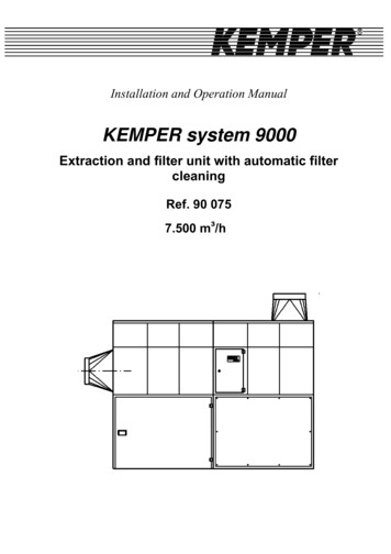
13Y7Y1 bis Y9 Magnetic-ValvesY10 Air-Service-UnitY11 Compressed-Air-Tank (25 L)Y12 Safety-ValveY8Y13 Pressure-Regulating-ValveY14 Hand-Lever-Valve(Lift forDust-Container)Y9Y15 Pneumatic ActuatorY16 Pressure Switch1012DatumPneumatic ComponentsBearb. GHKGepr.Ž nderungDatumNameNorm01.Okt.2003(Schema)CENTRAL SUCTION-UNITUrspr.Ers.f.Ers.d.02-E-504-1-12/390075 11Bl.12Bl.
012St ckliste (PARTSBauteilbenennung(PART NAME)345678LIST)Menge9WUPO003D 24.02.1994Bezeichnung(QUANTITY)(DESCRIPTON)Typen NummerLieferant(TYPE NO.)(SUPPLIER)Artikelnummer(PART NO.)PE21COVER 11MOTOR-PROTECTION-RELAY1180297SIE.3RB 1026-1QB0M11MOTOR1300047VENTILATORMOTOR 11KWF21CLAMP WITH FUSE3601558PH . 2XSECSPS.01PLC3601563SIE.6ES7 -1AL20BU.21SOCKET Typ: Binder 7233601229BIN.723.3POLIGP11PRESSURE NVERTER3601382TRŽ .DDM.1BU.31SOCKET Typ: Binder 7233601230BIN.723.5POLIGSPS.11PLC3601681SIE.6ES7 222-1HF21-0XA0CASE EARTHING11Datum22.M„r.2002Parts ListBearb. GHKGepr.Ž nderungDatumNameNorm01.Okt.2003CENTRAL SUCTION-UNITUrspr.Ers.f.02-E-504-1-12/390075Ers.d. 12Bl.12Bl.
European Community Declaration of Conformityaccording to European Community machine standard 89/392/EWG, appendix II AWe herewith confirm that the construction ofKemperCentral Exhaust- & Filter-UnitPart-No. 90 075is confirm with the following regulations:91/368/EWG89/336/EWGEuropean Community machine standard, appendix I No. 1EMV standard versionApplicable harmonized standards, especiallyEN 292 part 1 and part 2EMVGEG 87/404security of machinerylaw referring to the electromagnetic consistency of devicesregulation for compressed air reservoirsApplicable national and technical specifications, especiallyVDE 0100VDE 0113UVV VBG 1Vreden, 07.07.1998( i. V. M. Könning )construction of power plants with a nominal voltage of up to 1000Velectrical equipment of industrial machinesgeneral regulations
Deutschland/GermanyFrankreich/FranceKEMPER GmbHVon-Siemens-Str. 20D-48691 VredenTel.: 0 25 64/68 - 0Fax: 0 25 64/68 - 120mail@kemper.dewww.kemper.deKEMPER sàrlZI du RiedF-67590 Schweighouse Sur ModerTel.: 03 88 07 29 80Fax: 03 88 07 20 10mail@kemper.frwww.kemper.frTschechien/Czech RepublicPolen/PolenKEMPER spol. s r.o.Zděbradská 78CZ-251 01 Říčany-JažloviceTel.: 323 616 631Fax: 323 616 630mail@kemper.czwww.kemper.czKEMPER Polska Sp. z o.o.Al. Korfantego 2PL 40-004 ande/NetherlandsGroßbritannien/Great BritainKEMPER BVHartebroekseweg 58NL-7141 VE Groenlo VerkoopkantoorTel.: 0049-2564-68152Fax: MPER U. K. Ltd.Venture CourtDebdale Road / WellingboroughNorthamptonshire, NN8 5AATel.: 01327/872909Fax: paňa / SpainKEMPER America6659 PeachtreeIndustrial Blvd SSuite CNorcross, GA 30092Tel.: 770/416 7070Fax: 770/416 7306mail@kemper-usa.comwww.kemper-usa.comKEMPER IBÉRICA, S.L.C/ Ferrer y Guardia n 1Local 4 y 5E-08110 Montcada i Reixac(Barcelona)Tel.: (93) 572 62 90Fax: (93) 572 62 93mail@kemperiberica.eswww.kemperiberica.es
phases are connected. Please contact Kemper to check the unit if this reading appears again. Malfunction 3 E - 0 3 M O T O R T E M P E R A T T O O H I G H An optional accessory are temperature sensors in the motor. If the motor is getting too warm the machine switches off automatically and the above reading appears.