Transcription
Hygiene System KHSKEMPER hygiene systemPotable Water Cold (PWC)Good water hygiene by automatedmaintenance of the intended useSignificant reduction of flushed waterby controlled water change processesGüte ist bei uns die Norm · seit 1864Potable Water Hot (PWH) andCirculation (PWH-C)Temperature maintenance up to outletsUp to 40% heat loss reduction ofPWH-C pipework
Hygiene System KHSContentsTopicsPageKEMPER Hygiene System KHS – The innovative valve systemWhy does KHS make sense?Potable water hygiene maintained? Potable water installation – potential infection reservoirUnprofessional prevention of stagnation?Professional prevention of stagnation!KHS Flow Splitter -static- for PWCKHS Flow Splitter -dynamic- for PWC and PWHCharacteristics of the KHS Flow SplitterInstallation principles of the KHS Flow Splitter -dynamic In PWC In PWH In combination with the Inliner system for PWH456789101112131415Components: KHS isolating valve KHS Control Plus measuring instrument KHS Mini Control System KHS Timer Set KHS Logic Control System1618202223Design software KEMPER Dendrit CAD24Installation Examples: Hospital Hotel School or kindergarden Sports Hall Appartment building Stadium, exhibition hall Home for the elderly, barracks26303234363840Wiring instructions422
Hygiene System KHS„Watermust flow!”„Water is a friendly elementfor those who are familiarwith it and know how tohandle it.“Johann Wolfgang von Goethe (1749 – 1832)Quality is our standard · since 1864
Hygiene System KHSKEMPER Hygiene SystemThe innovative valve systemPotable water hygiene, economy, ecology in focusAlready back in the 19th century, LouisPasteur said: „We drink 90 % of our illnesses!“And that makes it especially astoundingthat nowadays the maintenance of potablewater hygiene in building installations isstill often neglected. Maintaining potablewater hygiene can have direct impacts onour health.4Even just considering health reasons, establishing operational use as intended,e.g., through forced flow and selective water-change measures in the potable waterinstallation, is recommended in codes andstandards.KEMPER developed the KHS Hygiene System to enable compliance with the hygienerequirements in the potable water installa-tion. This is an innovative valve system toprevent stagnation and the consequentialnegative impact on the potable water quality. The KEMPER Hygiene System KHS guarantees that fresh potable water is alwaysavailable at each outlet.
Hygiene System KHSWhy does KHS make sense?Protection of potable water qualityThe KEMPER Hygiene System KHS canmake a decisive contribution to maintainpotable water hygiene in hot and coldwater installations of new and existingbuildings. Every building is a “prototype”because of its individual usage. Even twobuildings of the same kind cannot be com-pared – they are always specific objectsthat have to be regarded individually. The“intended usage”, which is the basic assumption for the design of potable waterinstallations, should be maintained afterinstallation of the system. KHS technologyshows new, innovative ways for potablewater installations in the meaning of potable water hygiene, economy and ecology. Installation and operation of KHS isan additional milestone in health and animportant contribution to our responsibility caring for our planet earth.POTABLE WATERECONOMYECOLOGYClean potable waterSaves financial fundsand resourcesProtects the environment andsaves energy Maintains the potable waterhygiene (microbiological, chemicaland physical) Prevention of stagnation bymaintaining the “intended usage”at all times Maintenance of the correct hotand cold water temperatures tominimize the proliferation ofpathogens, such as Legionella(PWC 25 C, PWH 55 C) Prevention of corrosion in thepiping system Sustainable water usage Providing “natural” water at all outlets Local water usage creates movementin the whole preceding pipework Reduction of heat losses in hot watercirculation systems Reduction of labour and operatingcosts by automated processes Documentation by hygiene protocolQuality is our standard · since 1864
Hygiene System KHSPotable water hygiene maintained?Potable water installation – potential infection reservoir.Hygienists consistently find inadequate water hygiene in potable water installations.are permanently stagnant and can be theorigin of a hygienic problem.The problems occur in cold and hot watersystems. Professionals claim stagnation tobe one of the main reasons for the changeof potable water becoming non-potablewater. Stagnation is a period of “non-use”of the water. During this time, the waterdoes not flow and is not consumed.The operator is responsible for the properfunction of the water installation of hisbuilding. Therefore it is usually recommended to remove the unused pipeworkfrom the potable water installation or toensure that the whole installation is “usedas intended”.The reason for stagnation can be old, unused pipework or periodically unusedrooms of a building. These pipe sections“Use as intended” means that an assumedfrequency of water usage during the designneeds to be maintained after the com-6missioning of the water installation. Thisoriginally assumed usage is often not metor the usage changes after a time, so thatcontrolled water changes have to be doneto maintain the potable water hygiene. Ifthe potable water consumption is not asdesigned in certain areas, pathogens canrender the entire system unusable.
Hygiene System KHSUnprofessional prevention of stagnation?The fight against pathogens in hot and coldwater is of prime importance for operatorsof big potable water installations and theirdaily business.So far, the T-installation is the commonpractice for potable water installations inpublic (hotels, hospitals, schools, etc.) andprivate buildings. The result is potentialstagnant pipework to the single outlets.For a frequent water change, extensive andcostly manual measures are performed.This flushing measures are ineffectivebecause they are neither monitored norcomprehensive. The flushing measures aredefined by the technical and hygiene personnel and are carried out by employees.Therefore they have to open and close several valves and outlets manually. This causes high operating and labour costs.Normal T-installation in the sanitary block. Stagnation areas with high contamination risksarise when there are seldom-used outlets.Labour-intensive water changing at every terminal point. Nowadays normal, but ineffectiveand expensive solutions are used to ensure the proper use as intended in buildings.Quality is our standard · since 1864
Hygiene System KHSProfessional prevention of stagnation!With the innovative valve system from KEMPERFrequent “water change”in loop installationTo avoid ineffective and cost intensivemeasures against stagnation, the aboveshown type of installation should be considered in the design of potable water installations.The innovative pipe installation in combination with the KHS Flow Spitter createsa frequent water change in the loop pipeKHS Flow Splitter Unit -dynamic-8work when water is used at a subsequentoutlet at the riser – even if there is no frequent use of water in the regarded loop.
Hygiene System KHSKHS Flow Splitter-static- for PWCGiovanni Battista VenturiSimply ingenious - ingeniously simple. Theprinciple discovered by Giovanni BattistaVenturi still meets all requirements eventoday. In his productive period (*1746 inBibbiano † 1822 in Reggio nell Émilia) healso developed the venturi pump and theventuri nozzle.The KHS Flow Splitter’s function is based onthe principle of the Venturi nozzle. The minimum pressure difference between Supplyline A and Return line B causes an inducedflow in the branch. The drive comes fromwater usage after the KHS Flow SplitterUnit. The entire water content in the branchis thus changed, stagnation is preventedand the water temperature is kept low.90%100%100%AWTBWC10%When does it make sense to use a KHSFlow Splitter Unit?A KHS Flow Splitter unit always makessense when a rarely used outlet can bedriven by a frequently used outlet.FS: KHS Flow Splitterrut: rarely used tapfut: frequently used tapFS1 FS 1 rut 1 futrutfutQuality is our standard · since 1864
Hygiene System KHSKHS Flow Splitter-dynamic- for PWC and PWHIngeniously simple – simply dynamicSmall flows in the main – lots of movementin the branch loop.5%100%With the KHS Flow Splitter -dynamic-, another step towards stagnation prevention has been achieved. With an additionalcomponent in the venturi nozzle, the KHSFlow Splitter is capable of achieving a maximum flow through the connected branchloops; even with the smallest flow rates inthe main or in the riser.ExplanationDuring small flow in the main, 95 % flowsthrough the loop!100%5%WHBWTWC95%Small volume flow in the main line or in the riser:The dynamic venturi nozzle remains nearly completely closed - nearly the entireflow needed for supply is driven through the loop. The opening pressure of the dynamicventuri nozzle is not reached.90%100%100%90%WTWHBWC10%KHS Flow Splitter -dynamic-10High volume flow in the main line or in the riser:The dynamic venturi nozzle opens - the majority of the flow passes directly throughthe flow splitter in the main line and a partial flow is diverted through the loop due to theventuri effect. The opening pressure of the dynamic venturi nozzle is reached.
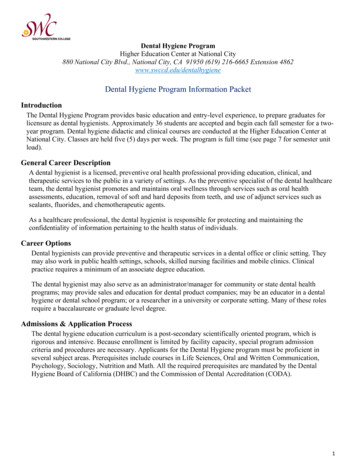
Hygiene System KHSCharacteristics of the KHS Flow SplitterDifferential pressure-static- and -dynamic-Dynamic Flow SplitterStatic Flow SplitterCirculationConsumption DynamicFlow Splitter Static or dynamicFlow SplitterThe diagram schematically portrays thepressure difference across the venturi nozzle dependent on the volume flow in thedistribution/riser branch (flow) for the KHSFlow Splitter -static and -dynamic-.Because of the additionally integrated cartridge in the KHS Flow Splitter -dynamic-,even at low volume flows, there is a higherpressure loss across the venturi nozzle ascompared to the KHS Flow Splitter -static-.That makes the KHS Flow Splitter -dynamicalso perfectly suited for use in hot potablewater installations to give circulation. During circulation mode, a sufficient waterchange is ensured in the ring lines.Flow rate in transitKHS Flow Splitter Unit-static-KHS Flow Splitter Unit-dynamic-Figure 640Figure 650Quality is our standard · since 1864
Hygiene System KHS - Application exampleInstallation principle of the KHS Flow Splitter-dynamic- in PWCConsumption in branchcreates movementStagnant water in pipes of occasionally unused outlets can be found in many potablewater installations. The installation of aKHS Flow Splitter -dynamic- prevents stagnation if a subsequent outlet at the riser isused frequently.The frequently and occasionally unusedoutlets need to be identified during thedesign phase by the operator and the designer to determine the adequate positionsfor the KHS Flow Splitter.Withdrawal atthe washbasinA hygienically safe installation with KHSFlow Splitter in the riser and an innovativepiping in the bath is shown on the right.The frequently used washbasin in the 3rdfloor causes a water change in the loopsof the lower baths, so that stagnation hasno chance!Principle: Water movement – effectively prevent stagnationFrequent water changeLow cold water temperatureWater movement in whole pipework12
Hygiene System KHS - Application exampleInstallation principle of the KHS Flow Splitter-dynamic- in PWHOptimised circulation with energy andeconomy benefitsIt is reasonable to use the KHS Flow Splitter-dynamic- in the hot water system of somebuildings. This depends on the shape of thebuilding and the routing of the pipeworkinside. As shown on the right side, outlets ina bathroom are connected via a KHS FlowSplitter -dynamic- and a loop installationin the bathroom. A hot water circulationpipe is not required in the corridor, as a hotwater circulation in the room installation isrealized by the KHS Flow Splitter and theloop installation. At the end of the corridor,the hot water pipework is connected to ahot water circulation riser via a thermalregulating valve (e.g. Figure 141 0G, MultiTherm). In periods without hot water consumption, the pump driven circulation volume is led through the whole pipework viathe venturi effect of the KHS Flow Splitterto maintain the hot water temperature inall loops.Withdrawal atthe washbasinIn case of water consumption at an outlet,e.g. at the washbasin on the 3rd floor, thisoutlet is supplied from both sides of theloop installation. This improves the supplysituation of each outlet.The reduced hot water circulation pipeworkcan lead to a 15 % heat loss reduction ofthe circulation pipework.Prevent stagnation and maintain the temperature effectivelyno stagnation due to KHS Flow Splitters and loop installationTemperature maintenance in the hot water pipework duringconsumption and circulation periods through loop installationQuality is our standard · since 1864
Hygiene System KHS - ComponentsInstallation principle of the KHS Flow Splitter-dynamic- in combination with the Inliner system for PWHThe inliner system is a hot water circulation pipe that is integrated in the hot waterpipe. The hot water flows in the main pipearound the circulation pipe. At the top ofthe riser, a special head piece is installedwhere the hot water enters the circulationpipe and flows the other direction back tothe water heater.KHS Flow Splitter Unit -dynamicfor Inliner systems Figure 660 00KHS Flow Splitter Unit -dynamicfor Inliner systems Figure 660 06100%ZirkulationThe benefits of this system are that no supports, insulation and wall breakthroughsare needed for a separate circulation pipe.The heat loss of the circulation pipeworkis reduced too. The combination of inlinersystem and the KHS Flow Splitter with loopinstallation maintains the temperature inthe whole hot water system till the outlet.5%5%95%Low hot water consumption downstream of the KHS Flow Splitter:The venture nozzle remains in minimumposition. Most hot water flows through theloop pipework of a connected room.100%Zirkulation100%90%90%10%100%14High hot water consumption downstream of the KHS Flow Splitter:The venture nozzle opens. Most hot waterflows through the main direction of theKHS Flow Splitter. A smaller percentage ofthe higher volume flow is driven throughthe loop pipework of a connected room.
Hygiene System KHS - Application exampleSuccessful combinationInliner-System with KHS Flow Splitter -dynamic-The KHS Flow Splitter -dynamic- for inlinersystems was developed for the Geberitinliner system.The inliner system can be implemented in buildings (e.g. senior citizens residences, hostels)in which one each sanitary supply unit per floor is placed on a PWH/PWHC riser branch.Quality is our standard · since 1864
Hygiene System KHS - ComponentsKHS Isolating ValveValves for water changingAutomatic water change in potable water installations can be realized with theKEMPER KHS Isolating Valve. This valve canbe used to avoid stagnation in main pipesof existing systems or to support the frequent water change in new systems thatare installed with KHS.If frequent use of all outlets cannot be guaranteed (e.g. school holidays), this valves incombination with KHS can be used to create a frequent water change in the wholepipework. The KEMPER KHS Isolating Valveis available as 230 V and 24 V version, flowlimited or unlimited version and with aservodrive with or without spring returnfunction.Controlling the KHS Isolating Valvewith servodrive:KHS TimerKHS Mini Control SystemKHS Logic Control SystemBuilding management systems (BMS)The KHS Isolating Valve with servodriveare available for optionally 24 volt and 230power supply.24 Volt e.g. for:KHS Logic Control SystemBuilding management systems (BMS)230 Volt e.g. for:KHS TimerKHS Logic Control System16KHS Isolating Valve with servodriveKHS Isolating Valve with spring return servodrive24 Volt:Figure 686 00 and Figure 696 00 (max. 2 l/min)230 Volt:Figure 686 04 and Figure 696 04 (max. 2 l/min)24 Volt:Figure 686 01 and Figure 696 01 (max. 2 l/min)230 Volt:Figure 686 05 and Figure 696 05 (max. 2 l/min)Note:To attain the best-possible water change (low water change volume) in the ring line,use the KHS Isolating Valve with servodrive Figure 696 in combination with the KHSFlow Splitter -dynamic-.If, due to local circumstances, the heat gain of the PWC line is very high so that it isnot possible to maintain a PWC temperature below 25 C in the mains, it is not possible to maintain the temperature with the KHS Isolating Valve with servodrive (Figure696 - max 2 l/min) during temperature controlled water changing processes. Eitheradditionally or alternatively to Figure 696, it is then necessary to employ Figure 686.The control of the additional KHS Isolating Valve with servodrive can be undertakenthrough the KHS-Timer Set or the BMS.
Hygiene System KHS - Application exampleKHS Isolating ValveApplication exampleThe KHS Isolating Valves can be used asterminals with spring-reset servodrive (example on the right) or in combination withvalves with servodrives in the riser branchplus a terminal valve with spring-reset servodrive (example below).If the second variant is selected, the controlmust be implemented through the KHSLogic control system or through the BMS. Ifthere is no permanent consumer in the potable water installation, the KHS-isolatingvalves can also be used as the drive for thepotable water installation.Recommendation:Collect the accruing water volumes foruse in a storage tank (e.g., rainwaterharvesting systems, fire extinguishingtanks, watering outdoor facilities, etc.)AM2nd UFM1st UFMGFMCDWCellarPotable water hygiene maintained by frequent water change in the pipeworkMMWZMWZ C CMWZ CWZ C2nd UFWZWZWZWZWZWZWZWZ1st UFGFMCDWCellare.g. storage tankQuality is our standard · since 1864
Hygiene System KHS - ComponentsCONTROL-PLUSHand-held measuring instrument for sensorsThe KEMPER CONTROL-PLUS portablemeasuring instrument is used in combination with volume flow (Figures 138 4G,638 4G), temperature (Figures 138 00 003300, 628 0G) or pressure sensors (Figure138 00 006 00) to determine the accuratevalues in the drinking water installation.This can be used for the hydraulic balancing of hot water circulation systems. It ispossible to measure the values or to recordtemperature, volume flow, pressure or velocity. The recorded values can be downloaded via USB interface and software onthe customers’ notebook. Maximum 4000values can be recorded.KEMPER Sensor Measurement ModuleThis module is used if a sensor is not connected to a BMS or KHS Logic Box. The sensors are usually installed at inaccessibleplaces in the ceiling void. The measurementbox can be installed below the ceiling voidto connect the portable measuring instrument within seconds to check the operating values of interest.The Measurement Module has threeimportant functions:1. It is used as a defined interface betweenportable measuring instrument and varioussensors in addition to CONTROL-PLUS, Pt100 and Pt 1000. Other sensors with a 4 20 mA or 0 - 10 V signal can be connectedto this box.2. The connected sensor and its positioncan be stored in the portable measuringinstrument.3. The measurement module enables totake measurements from sensors at inaccessible places.18CONTROL-PLUS hand-held measuringinstrument for sensorsFigure 138 00 002Sensor measurement moduleFigure 138 00 011
Hygiene System KHS - ComponentsCONTROL-PLUSHand-held measuring instrument for sensorsPt 1000 Temperature sensorFigure 628 0GSensor measurement moduleFigure 138 00 011Control Plus volume flow sensorFigure 138 4G, 638 4GPt 1000 portable temperature sensorFigure 138 00 003Pressure sensorFigure 138 000 006CONTROL-PLUS hand-held measuringinstrument for sensorsFigure 138 00 002Cable for pressure sensorFigure 138 00 016Quality is our standard · since 1864
Hygiene System KHS - ComponentsKHS Mini Control Systemfor small and medium size buildingsThe KEMPER KHS Mini Control Systemcan selectively implement water changingmeasures to maintain the potable waterhygiene in small and medium size building (e.g. schools, kindergartens, smallplants, industry, department stores, holidayhomes, etc.).Each box of the KHS Mini Control Systemcan be connected to a temperature sensor,volume flow sensor, KHS isolating valveand a free drain with overflow sensor andcan control the frequent water changes bytime, temperature or volume.KHS Mini Control System MASTER Figure 686 02 005 and SLAVE Figure 686 02 006The three operating modesTime controlled water changeTemperature controlled water changePreset water volumesMASTER/SLAVE technology applicationThe sophisticated modular principle with the practical accessories facilitates solvingcomplex requirements.20
Hygiene System KHS - ComponentsKHS Mini Control SystemThe MASTER/SLAVE technologyA single MASTER control box is the basicversion of the KHS Mini Control System.This is used to control the water changemeasures at one point in a drinking waterinstallation.The Mini Control System can beextended to a maximum of 1 Master boxand 31 Slave boxes, which are connectedin a row via CAN-BUS cable. 32 points withflushing valve, temperature and volumeflow sensor and free drain with overflowsensor can be controlled with this system.All boxes can be configured over the screenand the buttons on the Master box. As analternative, the configuration can be donewith software on a notebook, which is connected to the Master box via USB cable.The data of all water change processes isstored in the Master box. The log file of allprocesses can be downloaded and savedas an excel file. The Mini Control System isa decentralized system where the controlboxes are installed next to the point ofwater change. The wiring for the actuatorand sensors is kept very short by this kindof installation. Only the CAN-BUS cable hasto be installed between the single controlDetailed instructions for the wiring areavailable in the table on page 42.KEMPER KHS Mini Control System MASTER/SLAVEBase unit*Water change group** with components Any combination of the individual components can be selectedBase unitTime controlled water changeIndividual components Summary of functionsoperatingmodeboxes.In case of an error, a optical or visualalarm signal occurs and a transfer of thealarm signal to an existing BMS is possibleby dry contact.X X XCombined operating modesOverflow monitoring withalarm signal and latchingNumber of water change groupswith program allocationConfiguration andwater change log XXXXXXXXXXXXXXPresent water volumesTemperature controlled water change XX1 -MASTER- and max. 31 -SLAVES-USB cable software, connection -MASTER- with customer PC(min. system requirement: Windows XP or higher)* Base unit KHS Mini Control System: smallest functional unit is 1 -MASTER- and 1 KHS isolating valve** Water Change group contains max.: 1 Master or 1 Slave, 1 KHS isolating valve with spring return servodrive, 1 KHS temperaturesensor, 1 KHS volume flow sensor, 1 KHS free drain with overflow sensorQuality is our standard · since 1864
Hygiene System KHS - ComponentsKHS Timer SetSimple controlThe KEMPER KHS Timer Set is the smart solution to carry out scheduled water changes in drinking water installations to avoidstagnation. This simple and effective control box is basically installed in small andmidsize objects like schools, sports hallsand kinder gardens or in existing buildingsas basic system to create a frequent waterchange in the main pipework.KHS Timer SetFigure 686 08 and Figure 696 08 (max. 2 l/min)KHS Timer SetFigure 686 09 and Figure 696 09 (max. 2 l/min)22
Hygiene System KHS - ComponentsKHS Logic Control Systemfor large buildingsThe KEMPER KHS Logic Control Systemis the intelligent solution for controllingand monitoring water changing measuresto maintain the potable water hygiene inlarge buildings (e.g., hotels, hospitals, etc.).Along with performing the water changingmeasures and maintaining the temperature 25 C in the PWC, the KHS Logic ControlSystem can also monitor the temperaturelevel in the PWH/PWHC. The KHS LogicControl System is equipped with an alarmfunction to accomplish that. The operatingconditions (PWC and PWH) are automatically logged.KHS Logic Control System Figure 686 02 003The KHS Logic Control System can be flexibly used and can be centrally operated.Operating and reading out the waterchange logs requires a customer PC. It includes a programmable controller unit thatstores the water change programs. Motoroperated valves, temperature and volumeflow sensors, overflow monitors and KHSHygiene Flushing systems can be connected.For instructions on wiring, please see theKHS wiring table on page 42.The user can choose betweenthree operating modes:Time controlled water changeTemperature controlled water changePreset water volumes230 VQuality is our standard · since 1864
Simulation and calculation softwareKEMPER Dendrit CADInnovative software supports planning with KHSPowerful software is needed to be ableto portray, simulate and calculate complexsystems.In cooperation with Dendrit and in collaboration with additional competent marketpartners, KEMPER has developed a soft-ware that meets all the challenges resulting from the technology.KEMPER Dendrit CADKEMPER Dendrit CAD comprehensivelyprovides the planner with all the facilitiesof building-engineering planning: Selectionof the valves and pumps, design and drawing of the pipelines, calculation of the hydraulic conditions, simulation of the complete hot and cold water installation.Advantages at a glanceWith the CAD user interface and an innovative plan generatorTime savings through comprehensive, universal planningGlobal and comprehensive programme for precise calculation and simulation of building engineering plantsInnovative pipeline conduction plus ring lines in connection with the KEMPER valve range and the KHShygiene system in the cold potable water segment can be presented, calculated and simulatedSimulation of the water change in the PWC system using intelligent KHS isolating valve with servodrivePermanent support and improvements through the Münster University of Applied Sciences and Prof. Bernd Rickmann24
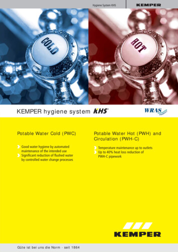
Simulation and calculation softwareAccurate determination of thevolume flows and flushingtimes for every branchScreenshot of KEMPER Dendrit software in PWC mode.After designing the drinking water installation, the necessarywater volumes and times for a water change in the systemcan be simulated.Display of the proceedingwater change in all loops ofall KHS Flow SplittersTotal duration for a completewater change in the entire waterinstallationDiagram of the pressuredifference at all KHS FlowSplittersPressure curve of theKHS Flow SplitterPlanning and operating reliabilityThe KEMPER Dendrit CAD software is aninnovative tool for designers to create anaccurate design of drinking water installations and other building services.It enables to create an installation designin a schematic or floor plan. The softwareincludes a so called “scheme generator”which helps to set up the basic drawing ofthe water installation in a building withoutdrawing it. A wizard requests some information about the general type of installation and the designer can place the outletsin a grid per drag & drop. This grid can beconverted to a schematic drawing.This easy way to create a basic drawing ofthe system saves much time that is usually needed to draw. All specific details ofthe drinking water installation (real pipelength, data of outlets, type of pipework,etc.) can be adjusted after creating a CADschematic. When all adjustments havebeen made, the software sizes the wholepipework and gives all information needed.The results for each pipe section and outletin the system can be saved as pdf-file. A billof quantities can also be saved as an excelfile.The complete designed drinking watersystem can be simulated in the KEMPERDendrit CAD software. The simulation ofthe PWC shows the simulation of the necessary water changes that are processedby the KEMPER Hygiene System (KHS). Theabove shown screenshot shows the simulation of a complete water change in thePWC system that is processed by the KHS.and PWH-C system helps to design a hydraulically balanced hot water circulationsystem, simulates the thermal disinfectionof the hot water system and contains a library of pumps that can be selected for thehot water circulation.The results of the simulation are used to setup the KHS Control System (Mini ControlSystem or Logic Control System) accordingto the required times and volume flows ofthe simulation. The simulation of the PWHQuality is our standard · since 1864
Planning examplesKHS application in large buildingse.g. hospital (distribution principle: horizontal)orKHS Flow Splitter Unit groupsFigure 650 00Figure 650 02In hospitals, it requires great effort for the operator to secure use asintended in the individual rooms. The rooms are not always occupiedor the sanitary objects are not constantly used by patients who areconfined to bed. Nowadays, building service providers secure thewater change in unused rooms by opening the tapping points. Onepopular variant in the pipe routing is the horizontal distribution withconnection of the individual sanitary blocks along the corridors. Toaccomplish that, the installation in connection with the KEMPER KHSHygiene System, calculated with the KEMPER Dendrit CAD calculationsoftware, is presented adjacent as an example.„Periodic flushing(1) in hospitals, doctor‘s offices and hotelsmust be ensured, independent of whether a room is occupiedor not.“(2)Regular water change with theKEMPER KHS Hygiene System through:KHS Flow Splitter Unit -dynamic- in the PWC and PWHSensors for monitoring and documentation(volumetric flow and temperature measurement)KHS isolating valve with servodriveWater change control using the KHS Logic Control Systemfor large buildingsRed
circulation systems The KEMPER Hygiene System KHS can make a decisive contribution to maintain potable water hygiene in hot and cold water installations of new and existing buildings. Every building is a "prototype" because of its individual usage. Even two buildings of the same kind cannot be com-pared - they are always specifi c objects