Transcription
Dell EMC Integrated System for MicrosoftAzure Stack HCI: Stretched ClusterDeploymentReference Architecture GuideAbstractThis reference architecture guide provides an overview of the Microsoft Azure StackHCI operating system and guidance on how to deploy stretched clusters in yourenvironment.Dell Technologies SolutionsPart Number: H18573February 2021
Notes, cautions, and warningsNOTE: A NOTE indicates important information that helps you make better use of your product.CAUTION: A CAUTION indicates either potential damage to hardware or loss of data and tells you how to avoidthe problem.WARNING: A WARNING indicates a potential for property damage, personal injury, or death. 2021 Dell Inc. or its subsidiaries. All rights reserved. Dell, EMC, and other trademarks are trademarks of Dell Inc. or its subsidiaries. Othertrademarks may be trademarks of their respective owners.
ContentsChapter 1: Introduction. 4Document overview. 4Audience and scope. 4Chapter 2: Solution overview. 5Introduction.5Stretched clusters and Storage Replica. 5Solution integration and network architecture.6Chapter 3: Solution deployment. 8Introduction.8Deployment prerequisites for stretched clusters. 8Customer network team requirements. 9Design principles and best practices.9Validated network topology.11Chapter 4: Creating a stretched cluster. 14Introduction. 14Test-Cluster. 14Cluster creation. 14Volumes. 16Storage efficiency. 17Test-SRTopology.17Chapter 5: Virtual Machines.18Introduction. 18VM and storage affinity rules.18Preferred sites. 18Chapter 6: Failure/Recovery from failure of Site/Node. 19Planned failover. 19Operation steps. 19Appendix A: Appendices. 21Appendix A: Sample PowerShell cmdlets for end-to-end deployment. 21Appendix B: Supported hardware. 25Contents3
1IntroductionThis chapter presents the following topics:Topics: Document overviewAudience and scopeDocument overviewThis reference architecture guide provides an overview of the Microsoft Azure Stack HCI operating system and guidance onhow to deploy stretched clusters in your environment. The guide provides network topology references and best practices toconsider during a stretched cluster deployment.The Microsoft Azure Stack HCI operating system can be deployed in both standalone and stretched cluster environments. Forthe deployment steps for a standalone cluster and end-to-end deployment steps with network and host configuration options,see the Network Integration and Host Network Configuration Options article.Dell Technologies offers integrated systems with the new Azure Stack HCI operating system. This guide applies to selectconfigurations of the integrated systems built using AX nodes.Audience and scopeThis guide is for systems engineers, field consultants, partner engineering team members, and customers with knowledge ofdeploying hyperconverged infrastructures (HCIs) with Windows Server operating systems and the newly released Azure StackHCI operating system (20H2).Customer site-to-site networking configuration and guidance is outside the scope of this document.AssumptionsThis guide assumes that deployment personnel have: 4Knowledge of AX nodes from Dell Technologies.Experience of configuring BIOS and integrated Dell Remote Access Controller (iDRAC) settings.Advanced knowledge of deploying and configuring Windows Servers and Hyper-V infrastructure.Experience with deploying and configuring Storage Spaces Direct Solutions with Windows Server or Azure Stack HCI.Familiarity with customer site-to-site networking, including enabling and configuring the necessary static routes or inter-sitebandwidth throttling (if needed) according to the stretched cluster requirement.Introduction
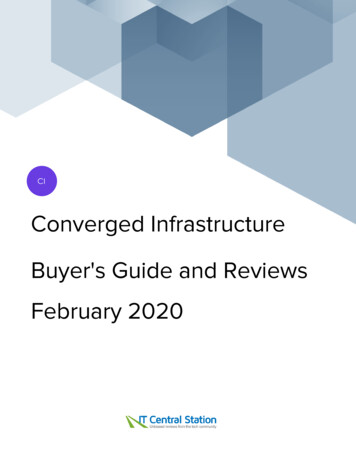
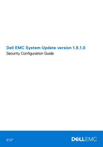
2Solution overviewThis chapter presents the following topics:Topics: IntroductionSolution integration and network architectureIntroductionDell EMC Solutions for Azure Stack HCI offers stretched cluster solutions with AX nodes from Dell Technologies. Built usingindustry-leading PowerEdge servers, AX nodes offer fully validated HCI nodes for a variety of use cases. A robust set ofconfigurations and different models allows you to customize your infrastructure for application performance, capacity, ordeployment location requirements.Stretched clusters and Storage ReplicaAn Azure Stack HCI stretched cluster solution is a disaster recovery solution that provides an automatic failover capabilityto restore production quickly, with little or no manual intervention. Storage Replica, a Windows Server technology, enablesreplication of volumes between servers across sites for disaster recovery. For more information, see Storage Replica overview.A stretched cluster with Azure Stack HCI consists of servers residing at two different locations or sites, with each site havingtwo or more servers, replicating volumes either in synchronous or asynchronous mode. For more information, see Stretchedclusters overview.A stretched cluster can be set up as either Active-Active or Active-Passive. In an Active-Active setup, both sites will activelyrun VMs or applications; therefore the replication is bidirectional. In an Active-Passive setup, one site is always dormant unlessthere is a failure or planned downtime.Sites can be on the same campus or in different places. Stretched clusters using two sites provides disaster recovery if a siteexperiences an outage or failure.Solution overview5
The following figure shows an Active-Active setup:Figure 1. An Active-Active setupSites can be logical or physical. For logical sites, a stretched cluster can exist on single or multiple racks or in different roomsin the same data center. For physical sites, the stretched cluster can be in different data centers on the same campus or indifferent cities or regions. Stretched clusters using two physical sites provide disaster recovery and business continuity should asite suffer an outage.Solution integration and network architectureDell EMC Solutions for Azure Stack HCI stretched clusters offer distinct network topologies that are validated with thefollowing stretched cluster configurations: Basic configuration High throughput configurationBasic configuration refers to a network topology that requires minimal changes to a traditional single-site Azure StackHCI configuration. This configuration uses a single network/fabric for management, VM, and replication traffic, keeping hostnetworking simple. The customer network team must configure quality of service (QoS) on an external firewall or routers tothrottle inter-site bandwidth and thereby ensure that Replica/VM traffic does not saturate the Management network.High throughput configuration suits customer environments that are dense and involves higher write IOPs compared toa basic configuration. This configuration requires a dedicated channel (network interface cards (NICs) or fabric) for Replicatraffic (using SMB-Multichannel). This network topology should be used only if inter-site bandwidth is higher than 10 Gbps. Thenetwork team must configure multiple static routes on the host to ensure that Replica traffic uses the dedicated channel thathas been created for it. If the customer environment does not use Border Gateway Protocol (BGP) at the ToR layer, static6Solution overview
routes are needed on the L2/L3 to ensure that the Replica networks reach the intended destination. Subsequent sections ofthis guide provide more information about the expectations of customer networking teams.A stretched cluster environment has two storage pools, one per site. In both topologies described in the preceding section,storage traffic requires Remote Direct Memory Access (RDMA) to transfer data between nodes within the same site. BecauseStorage and Replica traffic produces heavy throughput on an all-flash or NVMe configuration, we recommend that you putStorage traffic on separate redundant physical NICs.This table shows the types of traffic, the protocol used, and the recommended bandwidth:Table 1. Types of trafficTypes of trafficProtocol usedRecommended bandwidthManagementTCP1/10/25 GbReplicaTCP1/10/25 GbIntra-site storageRDMA10/25 GbCompute NetworkTCP10/25 GbHere are some points to consider about network configuration: Management traffic uses Transmission Control Protocol (TCP). Because management traffic uses minimal bandwidth, it canbe combined with Storage Replica traffic or even use the LOM, OCP or rNDC ports. VM Compute traffic can be combined with management traffic. Inter-site Live Migration traffic will use the same network as Storage Replica. Storage Replica uses TCP as RDMA is not supported for replica traffic over L3 or WAN links. Depending on the bandwidthand latency between sites and the throughput requirements of the cluster, consider using separate redundant physical NICsfor Storage Replica traffic.Solution overview7
3Solution deploymentThis chapter presents the following topics:Topics: IntroductionDeployment prerequisites for stretched clustersCustomer network team requirementsDesign principles and best practicesValidated network topologyIntroductionStretched clusters with Dell EMC Solutions for Azure Stack HCI can be configured using PowerShell. This guide describes theprerequisites for this deployment.NOTE: The instructions in this guide are applicable only to the Microsoft Windows Azure Stack HCI operating system.Each task in this deployment guide requires running one or more PowerShell commands. On some occasions you might have touse Failover Cluster Manager or Windows Admin Center from a machine that supports Desktop Experience.Deployment prerequisites for stretched clustersDell Technologies assumes that the management services required for the operating system deployment and clusterconfiguration are present in the existing infrastructure. An internet connection is required to license and register the clusterwith Azure. Because Microsoft Azure Stack HCI operating system is a Server Core operating system, you require a system thatsupports Desktop Experience to access Failover Cluster Manager and Windows Admin Center. For more information, see theWindows Admin Center FAQ.Table 2. Deployment prerequisites for stretched clustersComponentRequirementsActive Directory Sites & SubnetsConfigure two sites and their corresponding subnets in ActiveDirectory so that the correct sites appear on Failover ClusterManager on configuration of stretched clusters.Configure Fault domains for each cluster if the IP subnets arethe same across both sites.WitnessCustomers can choose to have a File Share witness either at atertiary site or on Azure Cloud.Windows gingStorage-Replica with PowerShell Management Tools on allnodesFile server roleNetwork8Solution deploymentThe following requirements apply:
Table 2. Deployment prerequisites for stretched clusters (continued)ComponentRequirements If two sites have host networks in different subnets, noadditional configuration is needed for creating clusters.Otherwise, manual configuration of the cluster faultdomain is required. RDMA Adapters for Storage/SMB traffic. RDMA is not supported for Replica traffic across WAN. At least a 1 Gb network between sites for Replication andinter-site Live Migration is required. The bandwidth between sites should be sufficient to meetthe write I/Os on the primary site. An average latency of 5 ms or lesser for SynchronousReplication. There are no latency requirements or recommendations forAsynchronous replication. There is no recommendation from Microsoft regardingthe maximum distance between sites that a stretchedcluster can support. Longer distances normally translateinto higher network latency.Windows Admin Center NodeWindows features required:RSAT-ClusteringRSAT-Storage-ReplicaNumber of nodes supportedMinimum: 4 (2 Nodes per site)Maximum: 16 (8 Nodes Per Site)Number of drives supportedMinimum of 4 drives per node. Both sites should havethe same capacity and number of drives. Dell Technologiescurrently supports only an All-Flash configuration forstretched clusters.Tuning of cluster heartbeats(get-cluster).SameSubnetThreshold 10(get-cluster).CrossSubnetThreshold 20SDN/VM NetworkSDN on multi-site clusters is not supported at this time.For the maximum supported hardware configuration, see Review maximum supported hardware specifications.Customer network team requirementsDepending on the network configuration chosen, customers should ensure that the requisite end-to-end routing is enabled forinter-site communication. A minimum of one IP route or three IP routes based on Basic or High Throughput configuration isrequired for the environment.Depending on the network configuration, the customer network team may also need to add static routes on the switches or onLayer-3 to ensure site-to-site connectivity.Design principles and best practicesStretched clusters and Storage ReplicaA stretched cluster setup has two sites and two storage pools. Replicating data across WAN and writes on both sites resultsin lower performance compared to a standalone Storage Spaces Direct Cluster. Low latency inter-site links are necessary forSolution deployment9
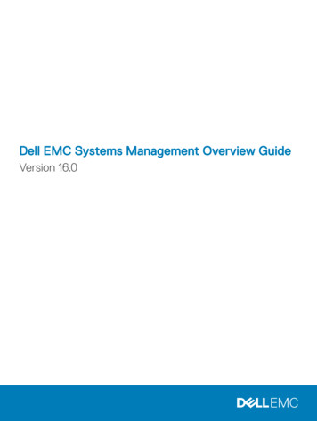
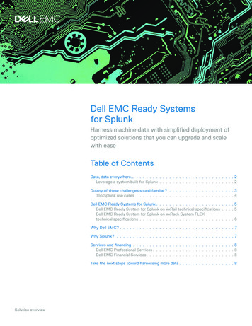
optimum performance of workloads. Low bandwidth and high latency between sites can result in very poor performance on theprimary site in the case of both synchronous and asynchronous replication.Synchronous replication involves data blocks being written to log files on both sites before being committed. In asynchronousreplication, the remote node accepts the block of replicated data and acknowledges back to the source copy. Applicationperformance is not affected unless the rate of change of data is faster than the bandwidth of the replica link between the sitesfor large periods of time. This point is critical and must be taken into consideration when you are designing the solution.The size of the log volume has no bearing on the performance of the solution. A larger log collects and retains more write I/Osbefore they are wrapped out. This allows for an interruption in service between the two sites (such as a network outage or thedestination site being offline) to go on for a longer period.Table 3. Disk writesScenarioWrites in two-way mirrored volumesWrites in three-way mirroredvolumesStandalone storage spaces2x3xReplication to secondary site4x6xNOTE: WAN latency and additional writes to log volumes on both sites causes higher write latency. Along with writes tothe log and data disks, the inter-site bandwidth and latency also play a role in limiting the IOPs in the environment. For thisreason, we highly recommend using all-flash configurations for stretched clusters.NOTE: In a Storage Spaces Direct environment both data and log volumes eventually reside on the same SSD pool becausemultiple storage pools per site are not supported.The following figure illustrates the difference between synchronous and asynchronous replication:Figure 2. Synchronous and asynchronous replicationSynchronous replication: A block of data written by an application to a volume on Site A (1) is written first to thecorresponding log volume on the same site (2), and is then replicated to Site B (2). At site B, the block of data is writtento the Replica log volume (3) before a commit is sent back to the application using the same route (4 and 5). The block issubsequently pushed to the data volumes on both sites. For each block of data that the application writes, the commit is issuedonly after data is written to the secondary site. Thus there is no data loss at file system level in the event of a site failure. Thisresults in a lower application write performance compared to a standalone deployment.Asynchronous replication: A block of data written by an application to a volume on Site A (1) is written first to thecorresponding log volume on the same site (2). A commit is immediately sent back to the application. At the same time,the block of data is replicated to Site B and written to the Replica log volume. In the case of a site failure, the cluster ensuresthat no data is lost beyond the configured Recovery Point Objective (RPO). Application performance is not affected unless the10Solution deployment
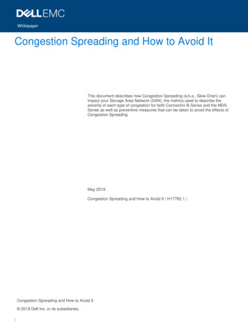
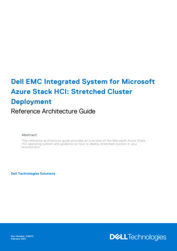
rate of change of data is faster than the bandwidth of the replica link between the sites for large periods of time. This is criticaland must be taken into consideration when designing the solution.NOTE: Both replication scenarios affect application performance because each data block has to be written multiple times,assuming that all volumes are configured for replication.NOTE: Stretched cluster with Storage Replica is not a substitute for a backup solution. Stretched cluster is a disasterrecovery solution that keeps a business running in the event of a site failure. Customers should still rely on application andinfrastructure backup solutions to recover lost data due to user error or application/data corruption.Validated network topologyBasic configurationThis section describes the host network configuration and network cards that are required to configure a basic stretchedcluster. The purpose of this topology is to keep the host and inter-site configuration simple with little or no change to a standardstandalone cluster networking architecture.Here we use two 25 GbE NICs for each host on both sites. One NIC is dedicated to intra-site storage traffic, similar to astandalone Storage Spaces Direct environment. The second NIC is used for management, compute, and Storage Replica traffic.To ensure management traffic is not bottlenecked due to high traffic on the Replica network, we request the customer networkteam to throttle traffic between the two sites using firewall or router QoS rules. It is recommended that the network is throttledto 50 percent of the capacity of the total number of network cards supporting the management NIC team.The management network is the only interface between the two sites. Because only one network pipe is available between thehosts on Site A and Site B, you will see the following warning in the cluster validation. This is an expected behavior.Node SiteANode1.Test.lab is reachable from Node SiteBNode1.Test.lab by only one pair ofnetwork interfaces. It is possible that this network path is a single point of failurefor communication within the cluster. Please verify that this single path is highlyavailable, or consider adding additional networks to the cluster.Table 4. Sample IP address schemaSite ASite BType of trafficManagement/Replica site Storage (RDMA) - 1192.168.101.0/24192.168.201.0/24L2Intra-site Storage (RDMA) - 2 eNetworkAs per customer environmentL2/L3As per customer environmentThe following figure shows the network topology of a basic stretched cluster:Solution deployment11
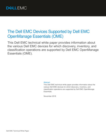
Figure 3. Network topology for a stretched cluster (basic)High throughput configurationIn this topology we use two 25 GbE and one 1/10 GbE/25 GbE NICs for each host to configure a high throughput stretchedcluster. One NIC is dedicated for intra-site RDMA traffic, similar to a standalone Storage Spaces Direct environment. Thesecond NIC is used for replica traffic. SMB Multichannel is used to distribute traffic evenly across both replica adaptersand it increases network performance and availability. SMB Multichannel enables the use of multiple network connectionssimultaneously, and facilitates the aggregation of network bandwidth and network fault tolerance when multiple paths areavailable. For more information, see Manage SMB Multichannel.The Set-SRNetworkConstraint cmdlet is used to ensure replica traffic flows only through the dedicated interfaces and notthrough the management interface. Run this cmdlet once for each volume.IP Address schemaThe following table shows the IP Address schema:Table 5. IP Address schemaSite ASite BType of 2/L3Intra-site Storage (RDMA) - 1192.168.101.0/24192.168.201.0/24L2Intra-site Storage (RDMA) - 2 192.168.102.0/24192.168.202.0/24L2Replica - 1*192.168.111.0/24192.168.211.0/24L2/L3Replica - 2*192.168.112.0/24192.168.212.0/24L2/L3VMNetworkAs per customer environmentAs per customer environmentL2/L3Cluster IP192.168.100.100192.168.200.100L2*Static routes are needed on all hosts on both sites to ensure the 192.168.111.0/24 network can reach 192.168.211.0/24 and the192.168.112.0/24 network can reach 192.168.212.0/24. Static routes are needed in this network topology because we have threenetwork pipes between Site A and Site B. Network traffic on Management uses the default gateway to traverse the network,while Replica network uses static routes on the hosts to reach the secondary site. If your ToR switches do not have BGPconfigured, static routes are needed on them also.12Solution deployment
The following figure shows the network topology of an advanced stretched cluster:Figure 4. Network topology for a stretched cluster (advanced)Solution deployment13
4Creating a stretched clusterThis chapter presents the following topics:Topics: IntroductionTest-ClusterCluster creationVolumesStorage efficiencyTest-SRTopologyIntroductionThis section outlines the steps that are needed for configuring a stretched cluster. Complete the network configuration onall nodes for the network topology applicable to you. A sample IP address schema is provided for both supported networktopologies in the previous section of this guide. Consider these points before you begin: Ensure management IPs of all nodes are reachable from any host Ensure static routes are configured on all hosts for inter-site communication using the Replica network Ensure all nodes from Site A can reach corresponding Replica IPs on Site B using the Replica pathTest-ClusterTest-Cluster is a fundamental function that is needed to ensure that the cluster to be created meets Microsoft'srecommendations regarding Failover Clustering. It also ensures that your hardware and settings are compatible. Run TestCluster with all nodes and include All Tests (namely, 'Storage Spaces Direct', 'Inventory', 'Network' and 'System Configuration').Ensure there are test-cluster passes without warnings for the 'High Throughput Configuration', while 'Basic Configuration' willreceive a warning as mentioned in the previous section of this guide.Cluster creationThis section looks at creating a cluster using PowerShell cmdlets.Manual cluster creationOnce Test-Cluster completes successfully, use the New-Cluster cmdlet to create a new stretched cluster. Because the nodesspecified are part of different IP schemas, Enable-ClusterS2D understands that the cluster is part of a multi-site topology. Itautomatically creates two storage pools and corresponding ClusterPerformanceHistory volumes and their replica volumes.After a cluster is created, you will see a warning similar to the one shown below. This is an expected behavior.No matching network interface found for resource 'Cluster IP Address 172.18.160.160' IPaddress '192.168.200.100' (return code was '5035'). If your cluster nodes span differentsubnets, this may be normal.Configure cluster witness and Enable Storage Spaces Direct on the cluster.NOTE: Cluster witness can be either on a tertiary site or on Azure Cloud. Ensure that the "Storage Replica" feature isinstalled on all nodes in the cluster.14Creating a stretched cluster
If Sites and Services with IP Subnets are configured on Active Directory, Failover Cluster Manager correctly shows a node toSite mapping, under Cluster Name Nodes.The following is a sample image of IP subnets defined in an Active Directory:Figure 5. IP subnets in an Active DirectoryIf both sites are in the same IP network, use the New-ClusterFaultDomain cmdlet to define the two site names. Site namesdefined using New-ClusterFaultDomain override the names given in Active Directory.The following is a sample image of how sites appears in Failover Cluster Manager:Figure 6. Sites in Failover Cluster ManagerOnce a cluster is created, use Failover Cluster Manager to rename the cluster networks.Creating a stretched cluster15
Figure 7. Cluster networksVolumesReplication-enabled volumes can be created using a combination of PowerShell and Failover Cluster Manager or by usingWindows Admin Center.NOTE: Install Storage Replica Module for Windows PowerShell (RSAT-Storage-Replica) on the management node withDesktop Experience that is used for installing Windows Admin Center and Failover Cluster Manager to access the cluster.For each replica-enabled volume, you need a corresponding log volume on both sites (with a minimum of 8 GB in size) and anequivalent replica volume on the secondary site. The log volume is used to serialize writes for replication.The following table shows the volumes that are needed to create a 1 TB replica volume:Table 6. Volumes in a 1 TB replica volumeSite ASizeSite BSizeVolumeA1 TBVolumeA-Replica1 TBVolumeA-Log40 GBVolumeA-Replica-Log40 GBVolumeB500 GBVolumeB-Replica500 GBVolumeB-Log40 GBVolumeB-Replica-Log40 GBSee Appendix A for the correct PowerShell Cmdlets and Failover Cluster Manager steps to create the volumes shown in thistable. It is recommended that you create two-way mirrors for all volumes to improve write performance and capacity efficiency.NOTE: For Asynchronous Replication, the RPO can be set as low as 30 seconds.For a planned site failure, when the volume replication direction is reversed, the disk reservations on the secondary site forReplica Volume and Replica-log volumes are removed and moved to the primary site. Source Data and Source Log volumes aregiven the disk reservations and become active on the secondary site. After 10 minutes, the virtual machines residing on theprimary site associated with the migrated volume automatically Live Migrate to the secondary site.16Creating a stretched cluster
Storage efficiencyDue to high I/Os on the underlying disks, stretched clu
Dell EMC Solutions for Azure Stack HCI stretched clusters offer distinct network topologies that are validated with the following stretched cluster configurations: Basic configuration High throughput configuration Basic configuration refers to a network topology that requires minimal changes to a traditional single-site Azure Stack HCI .