Transcription
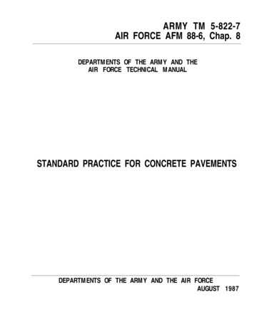
ConcreteSystemInstallation ManualMarch 2009
Contents1 System Advantages and Benefits1.1 Why Is Radiant So Comfortable21.2 Application Benefits32 System Design2.1 Creating a Concrete System Material List2.2 Heat Loss Calculations for Floor HeatingSystems Using Radiant WizardT2.3 Calculating the Supply Water Temperature2.4 Calculating the Floor Surface Temperature2.5 Calculating the Pressure Drop2.6 Selecting the Pump2.7 Typical Cross Sections2.8 Schematics - Piping and Controls2.9 Zone Wiring3 Concrete System Installation3.1 Layout Planning3.2 Concrete System Installation4 System Start-Up4.14.24.34.44.5Station and Actuator InstallationPurging and Pressure TestingInitial BalancingAdjusting the High Limit Kit, Diverting ValveFinish floors and Radiant HeatingAppendix ABTU Output Charts67891013161720232424252627Appendix BExpansion JointsViega IM-PR-Concrete 030956302 of 31
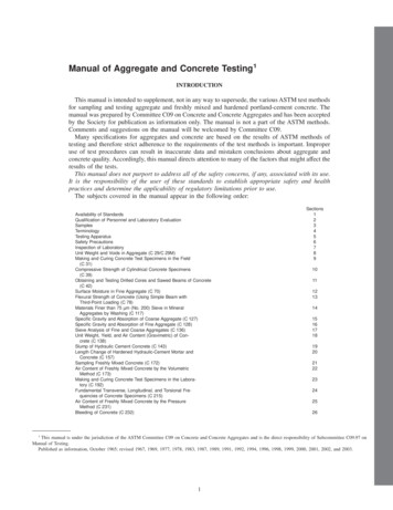
SYSTEM ADVANTAGES AND BENEFITS - CHAPTER 11.1 Why Is Radiant So ComfortableEven Heat DistributionIdeal Heating CurveFor maximum comfort, the warmest temperature is at floor level and coolertemperatures are at head and ceiling levels. By comparing the four mainheat distribution systems (see below) one can easily see that in forced air,radiators, and convective baseboard heating patterns, heat becomestrapped at the ceiling level, causing an inversion of the ideal heating pattern.Figure 1.1aQ: Is there energy being wasted fromcertain heating systems?Radiant Floor Entire floor surface areais in effect a lowtemperature radiator Warms other surfaces in thatroom and they, in turn,become heat emitters Has superior energy efficiencyA: Yes, the area between the idealheating curve and each specificheating system curve representswasted energy, which causeshigher monthly fuel bills.Figure 1.1bFigure 1.1cRadiators Most of the heat is deliveredby convection Operates at highwater temperatures Creates convective warmair currentsFigure 1.1eFigure 1.1dBaseboard (natural convection) Has minimal surface area Operates at highwater temperatures Tends to create unevenpools of warmth3 of 31Forced Air Drafts may occur High temperature air may beblown at occupants Exact opposite of the idealheat curve, i.e. cold feet andhot headViega IM-PR-Concrete 0309
1.2 Application BenefitsSlab on GradeUsed in new single storyslab houses Typical tubingspacing 9" on center.Figure 1.2aBathrooms/FoyersA thin-slab (lightweight pour) is agood medium in some marble orceramic tile finish floor applications.Thin-slabs may also be used overthick mud jobs. Typical tubing spacing6" on center.Figure 1.2bGarages/WorkshopsFigure 1.2cIdeal for heating garages. Makesworking in the shop comfortable.Dries floors and cars in the wetwinter weather. Helps preventtracking unwanted snow and dirtinside in the winter. Typical tubing spacing12" on center.New BasementsRadiant heating in the slab makes amore comfortable basement. It alsodecreases the downward heat lossthrough the first floor. Typical tubing spacing12" on center.Figure 1.2dViega IM-PR-Concrete 03094 of 31
SYSTEM DESIGN - CHAPTER 22.1 Creating a ConcreteSystem Material List Calculate the net heated area. Use this chart to make an initialmaterial list for the net area tobe heated.Note: This estimation does notinclude controls.ViegaPEX Barrier / Net HeatedFostaPEX Tubing*AreaMultiplier6" Spacing2.29" Spacing1.612" Spacing1.1* Sizes 1/2", 5/8", 3/4"Table 2.1aFasteners*EstimatedAmountNet HeatedAreaMultiplier6" Spacing1.19" Spacing.7512" Spacing.55EstimatedAmount* Various fasteners availableTable 2.1bEquation:Net Heated Area x Multiplier Estimated amountNet Heated Area 510 ft2Use this room accompanied with thechart to practice estimating.SolutionsRemember this chart is only forestimating. The number of circuits inthe area will be covered in section3.1 Layout Planning. Installer’spreference determines choiceof fasteners.Note:Changing tubing size does notnecessarily give you a higher heatoutput (remember the floor is themain heat emitter). The larger tubingallows for longer circuit lengths(Refer to section 3.1 for maximumcircuit lengths).Figure 2.1ViegaPEX Barrier / Net HeatedFostaPEX Tubing*AreaMultiplierEstimatedAmount6" Spacing510 ft22.21,122 ft9" Spacing510 ft21.6816 ft12" Spacing510 ft1.1561 ft2* Sizes 1/2", 5/8", 3/4"Table 2.1cFasteners*Net HeatedAreaMultiplierEstimatedAmount6" Spacing510 ft21.1561 pc9" Spacing510 ft.75383 pc12" Spacing510 ft.55281 pc22Table 2.1d* Various fasteners availableTubing is sold in coils and fasteners in packages5 of 31Viega IM-PR-Concrete 0309
2.2 Heat Loss Calculationsfor Floor Heating SystemsUsing Radiant WizardTMThe easy-to-use Radiant Wizardprogram will calculate the heatloss of any building. Based onASHRAE formulas, the RadiantWizard will also perform a full,multi-temperature, detaileddesign and quote for your system.A step-by-step users manual isprovided with the program.Contact your local representativeto receive a copy of the RadiantWizard program.Figure 2.22.3 Calculating the Supply Water Temperature4 Inch Slab on or Below Grade Application9" Tubing SpacingFigure 2.3Based on 68 F room temperaturewith 1/2" Pex tubing and R5insulation below the slab.Viega IM-PR-Concrete 0309Procedure:1. Locate desired BTU output(from Radiant Wizard) on leftvertical axis.2. Follow to the right until youreach the selected totalR-value curve.3. Then move down to the horizontalaxis and read the supplywater temperature.6 of 31Example:Output needed: 20 BTU/h/ft2Finish floor R-value: 0.25Supply water temperature: 112 F
2.4 Calculating the Floor Surface TemperatureThis chart shows the relationshipbetween room temperature andfloor surface temperature for floorheating systems.Procedure1. Locate required output (fromRadiant Wizard or other source)on left vertical axis.2. Follow to the right until youreach the curve.3. Then move down to thehorizontal axis and readthe T between the roomtemperature and the floorsurface temperature.4. Add the room temperatureand the T to get the floorsurface temperature.ExampleOutput needed: 25 BTU/h/ft2Room temperature: 68 F T (from chart): 12 FFloor surface temperature:68 F 12 F 80 FThe floor surface temperature will be80 F with 25 BTU/h/ft2 output and68 F room temperature.Floor Surface Temperature ChartFigure 2.47 of 31Viega IM-PR-Concrete 0309
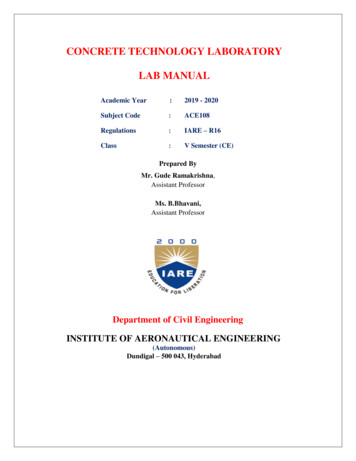
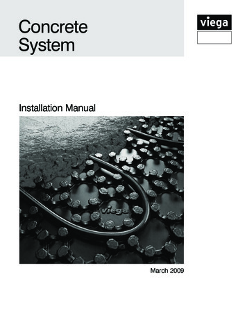
2.5 Calculating the Pressure DropIn order to select the correct pumpsize for the system, the pressuredrop must be calculated. Use thechart below to calculate thepressure drop.ViegaPex Tubing Data TableOutside Diameter(in.)Inside Diameter(in.)Water /20.6250.4750.0095/80.7500.5740.014Nominal Size(in.)Procedure1. Locate desired flow rate for onecircuit on the left vertical axis(receive circuit flow rate fromthe Radiant Wizard program).2. Follow to the right until youreach the selected tubing size.3. Then move down to thehorizontal axis and read thepressure drop in feet of headper floor of tubing.4. Multiply pressure drop per footby length of longest 751.0530.0451-1/21.6251.2430.063Table 2.5ExampleGPM through 1/2" ViegaPEX Barrier: 0.7 GPMPressure drop per foot: 0.022 ft. of head / ft.Total pressure drop: 0.022 x 350 total ft 7.7 ft. of head/2”1”3 3303/4””20”3/876 64 4643 332 22/S /S /SFT FT FT1 11/SFT8 of 31107 7764321Viega IM-PR-Concrete 030910 10101/2”5/16320 20205/8”Figure 1
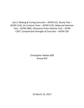
2.6 Selecting the Circulator PumpThe pump must have a capacity equal to the system flow rate and a head equal to the system pressure loss.These two system characteristics are the primary ones in selecting a pump. Flow rates come from the RadiantWizard program. Pressure drop comes from section 2.5 (Calculating the Pressure Drop) or from the Radiant Wizardprogram. Remember that for pressure drop, use the highest pressure drop of all the circuits fed by their circulator.If the circulator can overcome that pressure drop, then it can overcome all the others.Procedure1. Locate the pressure drop on theleft vertical axis.2. Locate the total system flow rateon the bottom horizontal axis.3. Follow to the intersection ofboth variables.4. Select the pump with a curvehigher than this point.Example (see below)Total GPM through 1/2" ViegaPEX:5 GPMFigure 2.6aLongest circuit pressure drop:10 ft of headPump selected:Low Head PumpStock LOW0.55601/25Stock 6-1/2"6"4-7/8"3-1/2"3-7/16"3-5/32"Stock W1.31501/6Figure 2.6b9 of 31Viega IM-PR-Concrete 0309
2.7 Typical Cross SectionsSection through slab on or below grade installation using Snap Panel Install insulation(R-5 minimum) Push PEX tubing intoSnap Panel in any directionPEX Tubing(1/2")SlabSnap PanelNote:A good general building practiceis to install a vapor barrier(polyethylene film) on top ofthe gravel; with Snap Panelthis is not needed.GravelGradeFoam BoardInsulation(1" minimum )Figure 2.7gSection through thin-slab installation using Snap Panel Push PEX tubing intoSnap Panel in any direction Allow minimum 3/4" heightof thin-slab over top ofPEX tubingPEX Tubing(1/2")1-1/2" Thin-slabSnap Panel Plywood staplesrecommended(U-clips may be substituted)PlywoodSubfloorFigure 2.7hViega IM-PR-Concrete 030910 of 31Min. R-19Insulation
Section through slab on or below grade installation using Wire Mesh Clips Install insulation(R-5 minimum) Install wire meshPEX Tubing(1/2", 5/8")Slab Fasten PEX tubing to wiremesh using Wire Mesh ClipsWire MeshClips Chairs/bricks may be used toraise the wire mesh and tubingto the mid point of the slabGravelGradeNote:A good general buildingpractice is to install a vaporbarrier (polyethylene film) ontop of the gravelFoam BoardInsulation(1" minimum )Figure 2.7cSection through slab on or below grade installation using Plastic Zip TiesPEX tubing(1/2", 5/8", 3/4" ) Install insulation(R-5 minimum) Install wire mesh Fasten PEX tubing to wiremesh using plastic zip ties.Cut end of zip tiesPlasticZip TiesSlab Chairs/bricks may be used toraise the wire mesh and tubingto the mid point of the slabGravelNote:A good general buildingpractice is to install a vaporbarrier (polyethylene film) ontop of the gravelGradeFigure 2.7d11 of 31Foam BoardInsulation(1" minimum )Viega IM-PR-Concrete 0309
Section through slab on or below grade installation using U-Channels Install insulation(R-5 minimum) Snap PEX tubing intoU-Channel (tubing insertionpoints are every two inches)PEX Tubing(1/2", 5/8")SlabU-ChannelGravelFoam BoardInsulation(1" minimum )GradeNote:A good general buildingpractice is to install a vaporbarrier (polyethylene film)on top of the gravel.Figure 2.7eSection through thin-slab installation using Plywood Staples Use the Viega PneumaticStaple Gun to staple PEXtubing to plywood subfloorwith plywood staples. ThePneumatic Staple Gun willleave a consistent 1/8"space above tubing.PEX Tubing(3/8", 1/2")1-1/2" Thin-slabPlywoodStaples Allow minimum 3/4" heightof thin-slab over top ofPEX tubing. Plywood staplesrecommended(U-clips may be substituted).PlywoodSubfloorFigure 2.7fViega IM-PR-Concrete 030912 of 31Min. R-19Insulation
2.8 Typical SchematicsSingle Temperature Radiant SystemThe Basic Heating Control isselected to modulate systemwater temperature as the outdoortemperature fluctuates. Multiplezones may be incorporated byadding Thermostats and aZone Control.MaterialMechanicalP1 Primary Loop PumpP2 System PumpS1 Mixing Supply SensorS2 Outdoor SensorS3 Indoor Sensor(optional)S3QuantityStock CodeMixing Station112120 - 12125Basic Heating Control116015Indoor Sensor116016Three Position Actuator118003Stainless Manifold, Shut-Off/Balancing/Flow Meter, # Outlets*115900 - 15910*Based on job requirementsB.H.C.B.H.CS2S1P2Primary Loop Sizing*P1CopperPipe 5450,000*Flow Rate and Heat CarryingCapacity calculation based on a 20 Ftemperature drop across the system.Note: All schematics are conceptual. The designer must determine whether this application will work in the system andmust ensure compliance with national and local code requirements. Boiler trim (expansion tank, fill valve, relays, etc.)supplied by others.13 of 31Viega IM-PR-Concrete 0309
Single Temperature Radiant System With Boiler Modulation and Optional DHW ControlThe Advanced Heating Controlincorporates low temperaturemixing, provides boiler modulation,and the option of domestic hotwater control with priority.Optional DHW sensor may be intank or on outlet piping. If boilerand DHW control is not needed,refer to Basic HeatingControl diagrams.MaterialQuantityStock CodeMixing Station112120-12125Advanced Heating Control116014Indoor Sensor116016Three Position Actuator for Station1180031-1/4" Stainless Manifold, # Outlets*115700 - 15710Thermostats*18002Powerheads315061Optional DHW Sensor116018Transformer 24V118008, 18020*Based on job requirementsA.H.C.A.H.CPrimary PumpSupply SensorS1P2System Pump3 PositionActuatorReturn Manifold3 Position ActuatorAir EliminatorBack Flow PreventorCold Water SupplyPressure Reducing ValveExpansion TankSupply ManifoldViega IM-PR-Concrete 030914 of 31
Multiple Temperature Radiant System With Boiler Modulation Note: If the heat loss andrequired water temperature variesthroughout a building, a multiplewater temperature system maybe required. To add an additionaltemperature system, pipe inanother Mixing Station with thenecessary controls.MaterialQuantityStock CodeMixing Station212120 - 12125Basic Heating Control216015Indoor Sensor216016Three Position Actuator for Station2180031-1/4" Stainless Manifold, # Outlets*215900 - 15910Zone Control218032Thermostats*18029 - 18031Powerheads*15061Optional DHW Sensor116018Transformer 24V118008, 18020*Based on job requirementsB.H.C.B.H.C.Primary Loop SizingCopper Pipe Size [inch]Flow Rate* [GPM]Heat Carrying Capacity 20,000450,000*Based on 6 FPS15 of 31Viega IM-PR-Concrete 0309
2.9 Zone WiringA manifold system allows anyone or more of the circuits tobe adapted for control by athermostat. The following aretypical zone wiring schematics.Detailed wiring diagrams areprovided with products.Important Note:Installation by a licensed electricianis recommended. Installation anduse of this equipment should bein accordance with provisions ofthe U.S. National Electric Code,applicable local code, and pertinentindustry standards.Wiring Schematic: One-Zone ApplicationDigital ThermostatC C R W NTC A/B24 VACTRANSFORMERFloor sensorWHITEBLACK120 VACINPUTNote: Digital Thermostats cancontrol up to 4 powerheads.Wiring Schematic: Multi-Zone ApplicationDigital ThermostatCCRWRWCNote: 4 Zone Control (18060)can operate 8 powerheads.6 Zone Control (18062) canoperate 16 powerheads.MainEnDSwiTCH4 & 6 Zone ControlTTboilErExTraEnDSwiTCHn/o CoM n/CSySTEM CirCulaTorDHw CirCulaTor120 VaCY1 Y2 R1 R2Viega IM-PR-Concrete 030916 of 31nEuTralHoT
CONCRETE SYSTEM INSTALLATION - CHAPTER 3Maximum Circuit Length3.1 Layout PlanningTo avoid waste and to have equalcircuit lengths, a carefully plannedlayout should be done. First,determine where the manifoldshould be installed. Remember themanifold must be accessible. Whencalculating the number of circuits,always round up. Keep the length ofeach circuit in the same room equal.Tubing 25 Btu’s / (hr x ft2)25 Btu’s / (hr x ft2 ) ble 3.1Calculating number of circuits:Total amount of tubing Maximum circuit length # of circuitsCircuit layout patterns for hydronic Radiant Floor HeatingExterior WallExterior WallExterior WallFigure 3.1aFigure 3.1bOne Wall SerpentineRoom has one exterior wallTwo Wall SerpentineRoom has two exterior wallsExterior WallExterior WallExterior WallFigure 3.1dFigure 3.1cThree Wall SerpentineRoom has three exterior wallsCounter FlowRoom has no exterior walls17 of 31Viega IM-PR-Concrete 0309
Manifold is located in the wall with access panelContinue serpentine pattern.Circuit 3Circuit 2Circuit 1Exterior WallFigure 3.1eUnheated areaManifoldRun supply tubing from red manifoldvalves into high heat loss areasfirst (i.e. closest to exterior walls,windows, sliders, etc.) and theninto the interior of the room.Higher water temperatures at theoutside wall will provide more BTUoutput where it is needed.Continue the circuits, laying themout in the same direction towardthe interior of the room.Figure 3.1fViega IM-PR-Concrete 030918 of 31
Tubing layout around jointsConcrete has very little flexibility andwill almost always crack. Jointingis one of the best ways to controlthe inevitable. Joint location, whichinfluences the radiant heating pipingdesign layout is generally specifiedby the architect.Typical Joint Locations Edge of thermal mass Side length 18' Sides less than 1:2 ratio Doorways Bays in L-shaped roomsIsolation JointsWhen installed against the concretefoundation at the perimeter ofthe slab, the joint material preventsthe slab from bonding to the walls.It also allows the slab to expandwithout cracking duringtemperature fluctuations.Control JointsControl joints force cracks to follow thepath of the joint. Without them, randomcracks will ruin the appearance andsometimes the usefulness of the slab.Slabs With Isolation And Control Joints1/2" Isolation joint(in radiant slabs 1/2"edge insulation is used)ControlJointsFigure 3.1hFigure 3.1gNote:Building or masonry supplycompanies sell 1/2" thickisolation joint material thatis precut to the thicknessof the slab.Isolation Jointsat pier and perimeterMinimize Penetration of JointsFigure 31iIncorrectFigure 3.1j19 of 31CorrectViega IM-PR-Concrete 0309
3.2 Concrete System InstallationFoam boardInsulation(1/2" min. R-2.5)Step 1Installing The Insulation Final grade should be accuratelyleveled. Cover grade with a polyethylenefilm (6 mill minimum).Insulation Recommendations When high water table - required Perimeter insulation - required At the thermal break - required(Between heated and unheatedslabs) Edge insulation - required In high heat loss conditions For small residential slabs( 2000 ft)Foam boardInsulation(1" min. R-5)Polyethylene Film(6 mil min.)FootingGravel3’GradeFigure 3.2aInsulation Benefits Increased response time Increased energy savings Improved thermal conductivity Decreased downward heat lossNote: Weigh down the foamboards to prevent wind uplift.In some jobs this can be done byinstalling wire mesh as soon asfoam boards are placed.Insulation recommended(R-5 min.).4 feet of perimeterinsulation is mandatoryto minimize highheat loss.Figure 3.2bNote: Check with local codes for requirements related to insulation.Viega IM-PR-Concrete 030920 of 31
Step 2Installing the TubingFasten tubing every two feet andthree times at each u-turn to holddown any return bends or othershapes created.It’s helpful to mark out portionsof each circuit directly on theinsulation using spray paint.The return bend can have akey hole shape to minimizethe tube spacing withoutkinking the tubing.Use bend supports in concrete.A bend support will help reducepossible damage to the tubingdue to the different expansionand contraction rates ofdifferent materials.Figure 3.2c21 of 31Viega IM-PR-Concrete 0309
Step 3Pressurizing the TubingPressurize tubing to 80 psi 24hours before pour and leavepressurized until slab is cured.Re-tighten any tubing couplingslocated in the slab area afterat least 12 hours ofsystem pressurization.Step 4Warming Up the SlabIt is best to warm the thermal massup slowly during start-up to helpprevent possible shock to the slab.In accordance with DIN 4725section 4, Viega recommends: Start warm up after concretehas reached its final set(curing complete). Set supply water temperatureto 77 F for the first three days. Increase supply watertemperature to the setpoint in gradual incrementsfor the next four days (maximumof a 50 F increase in a periodof 24 hours). Slab warm up should followthe concrete manufacturer’srecommendations.Step 5Testing the Concrete forExcessive MoistureThe polyethylene film test: tapea one foot square of 6 mil clearpolyethylene film to slab, sealingall edges with plastic moistureresistant tape. If, after 48 hours,there is no “clouding” or dropsof moisture on the undersideof the film, the slab can beconsidered dry enough forfinish floor applications.Drying times vary considerablywith location, season, interiortemperature/ humidity, etc.Follow the finish flooringmanufacturer’s recommendations.Concrete Thin-SlabsThe following may be added to themixture for flowability, and reducedshrinkage to minimize cracking;super plasticizer, water reducingagent, fiberglass reinforcing.Gypsum Thin-SlabsGypsum Thin-Slabs are usuallyinstalled after the walls have beenclosed in with drywall or otherfinish materials. The highly flowableGypsum mix fills in any gapsbetween the dry wall andthe subflooring reducing air leakageand sound transmission under walls.Note:Some installation methods call for the Thin-Slab to be constructedbefore any exterior walls or interior partitions are erected.To prevent bonding, all edges of the base plates that will be in contactwith the concrete slab should be coated with a suitable release agentcompatible with PEX tubing.Use a minimum of R-19 insulation under the plywood subfloor (refer tosection 2.7 Typical Cross Sections).Note: All tubing must be pressure tested prior to and during pour(Refer to section 4.2 Pressure Testing)Viega IM-PR-Concrete 030922 of 31
CONCRETE SYSTEM STARTUP - CHAPTER 44.1 Station and ActuatorInstallationMaterialProductQtyMixing Station1Three Position Actuator1Stainless Manifold, # outlets*1Basic Heating Control1Indoor Sensor1FostaPEX*Press Adapters4Compression PEX Adapters*1. Mount the Mixing Station usingthe mounting brackets.2. Make the press connectionfor the supply and returnlines to the Mixing Station onthe copper tee. Install teesas close as possible to keeppressure difference ata minimum.4. Use the SVC Compression orPEX Press Adapters to connectthe ViegaPEX Barrier lines tothe manifold.5. Remove the grey cap fromthe diverting valve on theMixing Station and screwthe actuator on hand tight*.*Based on job requirements3. Connect the supply andreturn lines by soldering on aViegaPEX Press adapter, thenpressing on ViegaPEX Barrieror FostaPEX .*Perform step 5 after the systemhas been filled and purged; refer tosection 4.2 for procedure.23 of 31Viega IM-PR-Concrete 0309
5.2 Purging and PressureTesting the SystemOperationPurging1. Attach drain hose to purgevalve hose connection on returnheader and open valve.2. Close all but one balancingvalve on supply header (underred caps, turn with 5mm allenkey). Close isolation ball valveon boiler return line. Removeplastic dust cap or temperaturecontroller from diverting valveand make sure that high-limit kitis fully open.3. Open boiler fast fill valve to purgecircuit. After purging first circuit,close red balancing valve andopen next one. Continue with onecircuit at a time until all circuitshave been purged.4. Close purge valve and openall balancing and boiler valves.Reset high-limit kit, and reinstallactuator onto diverting valve.the system will be eliminatedthrough the automatic air ventafter a few hours of constantcirculation.NOTE: If the system must bepurged again in the future for anyreason, the high-limit kit must bereopened during purging forfull flow.5. Any remaining air pockets inPressure TestingBefore the finish floor is installedthe radiant system must bepressure tested. Air or water maybe used as the medium.The following procedure isrecommended by Viega. Checkthe local building codes forcompliance or additionaltest requirements.Procedure:1. Double-check all connections tomanifold to ensure proper seal.2. Connect manifold pressurizationkit (1) to any purge valve (2).3. Pressurize the system to 80 psito detect potential nail or screwpenetrations.4. The system should hold the 80psi for a minimum of 24 hours.DivertingValveNote: If the tubing is damaged,repair punctured section with acompression coupling.Contractor: Maintain pressureduring the installation of the finishfloor to simplify leak detection iftubing is damaged.4.3 Initial BalancingMany times it is not possible to design the system using equal circuitlengths, so the system must be balanced in order to ensure adequate flowto each circuit on a manifold.(Refer to your Radiant Wizard design program for detailed balancing.)Procedure:1. Start with all valves wide open.2. To decrease flow, turn the balancing valve clockwise in small increments.Note: Remove red caps and turn balancing valves with included allen key.Valves are hidden to prevent tampering.Viega IM-PR-Concrete 030924 of 31
4.4 Adjusting the HighLimit KitOperationThe Mixing Station is providedwith a preinstalled temperaturehigh-limit kit. This kit isinstalled into the 3-way valve toallow a maximum supply watertemperature to be set. This kit mustbe unscrewed when purging thesystem, and should then be setaccording to the instructions below.25 of 31Viega IM-PR-Concrete 0309
4.5 Choosing aFinished FloorThere are three common types offinished floors used in residentialconstruction; wood floors, tile/vinyl,and carpet.When picking a finished floor, thelower the R-value, the better radiantheat will work. When using tile, theR-value will be low and thereforewill work very well with your radiantsystem. Vinyl flooring is anothercommon choice for kitchens andbaths and has a low R-value.Using carpet over radiant heatingrequires careful planning. Viega’srecommendation for a coveringover a radiant system is to notexceed a total of a 2.5 R-value (thecarpet pad plus the carpet itself).Remember that the pad and thecarpet are insulators and will restrictthe heat from getting into the room,so keeping the R-value of the padand the carpet low is a must. It maybe necessary to add supplementalheat or install hydronic baseboardsin rooms with heavy carpeting (seeViega’s Combiflex System).There are many questions regardinghardwood flooring over radiantheating. Armed with knowledge anda few precautions, hardwood floorsand radiant heat will work welltogether. There are twoimportant issues:1. Floor surface temperatures2. MoistureFloor Surface TemperaturesFor many builders, a reluctanceto install hardwood floors overradiant heat stems from problemsassociated with incorrect control ofthe floor surface temperatures.Viega IM-PR-Concrete 0309 Today, modern insulation andbuilding techniques allow aradiant floor to stay cooler thanthe floor of the average sunroom. The floor surface temperatureshould not exceed 85 F (refer tosection 2.4 to calculate the floorsurface temperature).Also be careful when using multipleor high R-value area rugs overhardwood flooring. Your radiantheating system must be designedwith this additional R-value takeninto account in order to performproperly. If the system wasdesigned for bare wood flooring,adding area rugs may lead toa situation where heat outputis diminished.If the moisture content is relativelyhigh near the top surface of theplank, it will crown downward onthe edges.Wet ExpansionSources from below: Inadequate moisture barrier Ground water wicking throughthe slab Unsealed subfloorMoistureSources from above:Allow the radiant system to run forat least a week before installingthe hardwood. This will ensure thatthe subfloor is dry. Wood flooringshould be acclimated to the job sitebefore installation. When checkingthe moisture content of the subfloorand wood flooring with a moisturemeter, aim for a reading of 6%to 8%. Moisture will affect thehardwood floor with or without aradiant system. High relative humidity Moisture absorption causes woodto swell. Moisture loss causes woodto shrink.If the moisture content of the woodis relatively high near the bottomof the plank, cupping upward willoccur exaggerating cracks.Dry Shrinkage26 of 31Both solid plank flooring andengineered wood floors areacceptable choices overradiant heating.Choosing narrower planksand harder woods minimizesdimensional change in thewood. Engineered wood flooringusually has less expansion andcontraction and can be a goodchoice to minimize gapsbetween planks.Note: Follow the flooringmanufacturer’s installationmanual or NOFMA’s (NationalOak Flooring ManufacturersAssociation) manual.
4 Inch Slab on or below Grade Application with 6" Tubing SpacingBased on 68 F room temperature with 1/2" ViegaPex Barrier tubing with R5 insulation below the slab.Figure Appendix A.a4 Inch Slab on or below Grade Application with 9" Tubing SpacingBased on 68 F room temperature with 1/2" ViegaPex Barrier tubing with R5 insulation below the slab.Figure Appendix A.b27 of 31Viega IM-PR-Concrete 0309
4 Inch Slab on or below Grade Application with 12" Tubing SpacingBased on 68 F room temperature with 1/2" ViegaPex Barrier tubing with R5 insulation below the slab.Figure Appendix A.c1-1/2 Inch Thin-Slab with 6" Tubing SpacingBased on 68 F room temperature with 1/2" ViegaPex Barrier tubing with R19 insulation below theFigure Appendix A.dViega IM-PR-Concrete 030928 of 31subfloor.
1-1/2 Inch Thin-Slab with 9" Tubing SpacingBased on 68 F room temperature with 1/2" ViegaPex Barrier tubing with R19 insulation below the subfloor.Figure Appendix A.e1-1/2 Inch Thin-Slab with 12" Tubing SpacingBased on 68 F room temperature with 1/2" ViegaPex Barrier tubing with R19 insulation below the subfloor.Figure Appendix A.f29 of 31Viega IM-PR-Concrete 0309
Section thru fibrous expansion joint (typical)6 - 8" Typ.Fibrous expansion joint: Coordinatewith architectural drawings forexpansion joint locations.ViegaPEX tubingSleeving (piece ofpolyethylene or PVC pipe)InsulationFigure Appendix C.aGravelSection thru metal expansion joint (typical)Metal expansion joint: coordinatewith architectural drawings
3 Concrete System Installation. 3.1 Layout Planning 17 3.2 Concrete System Installation 20. 4 System Start-Up. 4.1 Station and Actuator Installation 23 4.2 Purging and Pressure Testing 24 4.3 Initial Balancing 24 4.4 Adjusting the High Limit Kit, Diverting Valv