Transcription
No responsibility is taken for the correctness and completeness of this information - Date 05/2015System diagramsOnline training multiMATIC 700
System diagram 1No responsibility is taken for the correctness and completeness of this information - Date 05/2015 System with boiler: DHW regulation by boiler (except in solar systems)(System diagram 1, VR 70 configuration 3)2
System diagram 2No responsibility is taken for the correctness and completeness of this information - Date 05/2015 System with boiler: DHW regulation by VRC 700(System diagram 2, VR 70 configuration 1)3
System diagram 6No responsibility is taken for the correctness and completeness of this information - Date 05/2015 3 kW hybrid system (alternative operation mode): DHW only by boiler(System diagram 6, no VR 70)4
System diagram 7No responsibility is taken for the correctness and completeness of this information - Date 05/2015 3 kW hybrid system (parallel operation mode with 2 circuits / zones): DHW only by boiler(System diagram 7, VR 70 configuration 1)5
System diagram 8No responsibility is taken for the correctness and completeness of this information - Date 05/2015 Standard heat pump system, auxiliary heater requires pump of heat pump, monoenergy (DHW by heatpump and auxiliary heater or simple hybrid system (DHW by boiler only)(System diagram 8, no VR 70)6
System diagram 9No responsibility is taken for the correctness and completeness of this information - Date 05/2015 Simple hybrid system, auxiliary heater does not require pump of heat pump, DHW by boiler only(System diagram 9, VR 70 configuration 5)7
System diagram 10No responsibility is taken for the correctness and completeness of this information - Date 05/2015 Heat pump system with heat exchanger, auxiliary heater requires heat exchanger pump, monoenergy(DHW only by heat pump) (System diagram 10, no VR 70)8
System diagram 11No responsibility is taken for the correctness and completeness of this information - Date 05/2015 Standard heat pump system with heat exchanger, auxiliary heater requires pump of heat pump, monoenergy (DHW by heat pump and auxiliary heater) (System diagram 11, no VR 70)9
System diagram 12No responsibility is taken for the correctness and completeness of this information - Date 05/2015 Complete hybrid system, auxiliary heater does not require pump of heat pump (DHW by heat pump andboiler) (System diagram 12, VR 70 configuration 5)10
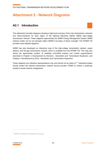
System diagram 13No responsibility is taken for the correctness and completeness of this information - Date 05/2015 Complete hybrid system with heat exchanger, auxiliary heater does not require pump of heat pump(DHW by heat pump and boiler) (System diagram 13, VR 70 configuration 1)11
No responsibility is taken for the correctness and completeness of this information - Date 05/2015Legend for system at generatorHeater generator pumpSwimming pool circulation pumpCHP system circulation pumpHot water charging pumpHeat pumpPassive cooling assemblyBuffer cylinderDomestic hot water cylinderDHW cylinder with pipe heat exchangerMulti-functional cylinderTank in tankSequence cylinderSolar combi cylinderGas cockThermostatic radiator valveUnit electronicsHeat generator control systemRemote control unitMixer moduleHot water charging controllerSystem controllerExpansion moduleSolar moduleeBUS bus couplerSwimming pool controllerCondensate pumpOutside temperature sensor/DCF receiverOutside temperature sensorDrinking water station (DWS)Hot water charging sensorCylinder temp. sensor for DHW gener.Limit thermostatFlush connectionFlue gas thermostatCut-off relayHome nSolar pump unitSolar charging systemDrinking water stationCylinder charging pumpZone valveThermal discharge safety deviceNon-return valveRegulating valveCap valveDirt trapSludge separator setIncrease in return flowMixer for increase in return flowFlow SwitchThermometerAir separatorDiverter valve (inside unit)Thermostat mixing valveHeat exchangerExpansion relief valveDiaphragm expansion tankDiaphragm expansion vessel for drinking waterSafety group for drinking water connectionLow loss headerPressure gaugeFlow meter (Taco setter)Bypass valveHydraulic blockIndividual room control valveHeat recovery moduleFlexible connectionsHeat pump brine filling unitBrine expansion vesselFilling and draining valveSolar automatic air vent with lockPurging valveVFK solar collector12
No responsibility is taken for the correctness and completeness of this information - Date 05/2015Legend for system R4R5/R6S1S2S3S4S5S6S7DescriptionVTK solar collectorSolar in-line vesselCollecting containerPump, cooling circuit3-way mixer3-way mixer, cooling3-way mixer, passive cooling assemblyFan coil convectorTundishAir collectorVWL 10/3 SA outer unitSuction well pumpSwimming poolCompact buffer r/solar temperature sensor/DJ-sensorCylinder/solar temperature sensor/DJ-sensorCylinder/solar temperature sensor/DJ-sensorFlow temperature sensor/DJ-sensorFlow temperature sensor/DJ-sensorFlow temperature sensor/DJ-sensorPWM signalDrinking waterDomestic hot waterCirculationWiringHeating flowHeating returnSolar flowSolar returnHeat source flowHeat source returnCooling flowCooling return13
(DHW by heat pump and boiler) (System diagram 13, VR 70 configuration 1) 11 System diagram 13 -5 12 Item Description Item Description 1 Heat generator 25 Solar pump unit 2 Heater generator pump 26a Solar charging system 2a Swimming pool circulation pump 26b Drinking water station 2b CHP system circulation pump 27 Cylinder charging pump .


![Linux File RAID [SQA Example] - Embry-Riddle Aeronautical University](/img/43/linux-file-raid-system-srs.jpg)