Transcription
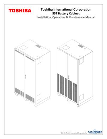
Toshiba International Corporation55T Battery CabinetInstallation, Operation, & Maintenance ManualBuilt for Toshiba International Corporation by
3/5/20152755-00041 R05
This manual contains proprietary and confidential information of C&C Power, Inc., and has beenprepared for the use of Toshiba International Corporation, for use in conjunction with equipmentprovided by C&C Power, Inc. Unauthorized reproduction, in whole or in part, without writtenpermission of C&C Power, Inc., is prohibited.Copyright 2015 C&C Power, Inc.All rights reserved.C&C Power, Inc.395 Mission StreetCarol Stream, IL 60188www.ccpower.comTechnical Support:Phone: (630) 617-9022Email: support@ccpower.com3/5/20153755-00041 R05
3/5/20154755-00041 R05
TABLE OF CONTENTS1. Important Information About This Manual . 61.1 Manual Symbols . 62. Introduction: . 73. Safety Precautions . 84. Inspection Upon Receipt of Goods. 104.1 General . 104.2 Visible Damage . 104.3 Concealed Damage . 104.4 Return of Damaged Goods . 105. System Overview . 116. System Specifications. 126.1 Batteries . 126.2 System Grounding . 126.3 DC Output . 126.4 General Specifications . 127. Installation . 147.1 Preparation. 147.1.1 Equipment Inspection . 147.1.2 Necessary Equipment and Tools . 147.1.3 Installation Safety Precautions . 147.2 Installation Steps . 157.2.1 Equipment Location . 157.2.2 Equipment Mounting . 157.2.3 Equipment Grounding . 157.2.4 DC Connections. 167.2.5 System Operation . 168. System Maintenance. 178.1 Battery Replacement . 179. Reference Materials . 1910. Warranty . 233/5/20155755-00041 R05
55T BATTERY CABINET1. IMPORTANT INFORMATION ABOUT THIS MANUALSAVE THESE INSTRUCTIONS! This manual contains important information that is neededduring the installation and maintenance of the system.1.1 MANUAL SYMBOLSWarning:Indicates information provided to protect the user against personal injury and/orsafety hazards.Caution:Indicates information provided to protect the user against safety hazards and/orpossible equipment damage.Important:Indicates information provided as an installation or operating instruction or tip aswell as general important installation and system information.3/5/20156755-00041 R05
55T BATTERY CABINET2. INTRODUCTION:The C&C Power family would like to thank you for choosing a C&C Power Inc. product for yourequipment needs. We know there are a lot of choices in the industry and we appreciate theopportunity to supply each of our customers with the highest quality power productsmanufactured in the United States today. All of C&C Power’s solutions are factory tested to someof the highest standards is the industry. Every battery cabinet system is Hi Pot tested to ULstandards at our facility prior to shipment.Sales support for future equipment needs or upgrades is provided by our regional sales staff andqualified representatives. All technical questions and service issues should be directed to ourmain office by dialing the number listed below. This is a 24-hour, 7-day service number. Afternormal working hours, please leave a detailed message with your phone number on the voice mailsystem and a qualified service representative will contact you as quickly as possible.C&C Power, Inc.395 Mission StreetCarol Stream, IL 60188www.ccpower.comTechnical Support:Phone: (630) 617-9022Email: support@ccpower.com3/5/20157755-00041 R05
55T BATTERY CABINET3. SAFETY PRECAUTIONSBefore installing or maintaining this system, it is extremely important to read thismanual and be sure that all system drawings and schematics are reviewed andclearly understood. If there are any questions concerning this manual or any of theinstallation or maintenance procedures and/or requirements please contact a C&CPower representative before proceeding.When installing this power system, follow all applicable federal, state and localregulations as well as industry guidelines to insure proper system installation.Only qualified electricians or DC power technicians should attempt to install orservice this equipment.System installation and maintenance should always be performed with heavilyinsulated tools. It is also recommended to wear rubber gloves, boots, and useinsulating mats to stand on when working on this equipment.Always wear eye protection when installing or maintaining batteries and/or powerequipment.Battery cabinet systems are extremely heavy. Use a minimum of two people whenunloading and setting equipment in place.Do not smoke or present open flames near any battery system.For the safety of others, never leave an open cabinet or panel unattended.To reduce the risk of fire, replace fuses with the same type and rating of fusessupplied with the system.DC Power and Batteries can be very dangerous and have extremely high shortcircuit current. Electrical shock, severe burns, fire or death can result from a systemshort.3/5/20158755-00041 R05
55T BATTERY CABINETTo avoid personal injury including electrical shock, severe burns and possibledeath, all jewelry including bracelets, rings and watches must be removed prior toinstalling or servicing this system.Do not open or mutilate batteries. Opened or severely damaged batteries canrelease toxic electrolyte which is harmful to the skin and eyes.Never lay loose cables, metal parts or tools on top of batteries.Under certain conditions, batteries can vent potentially explosive gas (hydrogen).Never enclose batteries or battery cabinets in a sealed room.3/5/20159755-00041 R05
55T BATTERY CABINET4. INSPECTION UPON RECEIPT OF GOODS4.1 GENERALSpecial precautions and care have been taken to ensure the system arrives safe and undamaged.However, upon receipt, you should inspect the entire shipment, including the crate and any boxesfor evidence of damage that may have occurred during transit.4.2 VISIBLE DAMAGEIt is the responsibility of the person receiving the shipment to inventory and fully inspect allmaterials against the bill of lading or weigh bill IMMEDIATELY while the carrier representativeis still present. Insure that all items are accounted for, including number of skids and quantity ofboxes. Also note any visible external damage that may have occurred during transit. Make allapplicable notations on the delivery receipt before signing and file a damage report with thecarrier.4.3 CONCEALED DAMAGEWithin 3 to 30 days of receipt (depending on courier), unpack the system and check for anyconcealed damage. Check the materials received against the detailed packing list to verify thequantity and the condition as complete and satisfactory.Note any damage to the internal packaging, then request an inspection by the carrier and file aconcealed damage claim. If there is a material shortage, contact a C&C Power representative atthe main office to file a claim.Please contact your shipping company for all shipping damage.C&C Power is not responsible for any shipping damage.4.4 RETURN OF DAMAGED GOODSShould equipment be damaged and require return to C&C Power for repair, a representative willprovide instructions along with an RMA number to expedite the return.A RMA number must be obtained before returning equipment to C&C Power, Inc.3/5/201510755-00041 R05
55T BATTERY CABINET5. SYSTEM OVERVIEWDuring normal operating conditions the UPS supplies power to the load as well as the necessarypower required to keep the batteries at the proper float voltage. When AC power fails, thebatteries will discharge in order to provide the necessary backup power to the load. It is theresponsibility of the customer to make sure the batteries are not discharged below manufacturesrecommendations. After any battery discharge has occurred, the batteries should be recharged assoon as possible. Batteries will be damaged if not properly recharged right away. See the UPSmanual for more information on charging the batteries.3/5/201511755-00041 R05
55T BATTERY CABINET6. SYSTEM SPECIFICATIONS6.1 BATTERIESPlease refer to system drawings for model specific information.Type: Valve Regulated Lead Acid (VRLA), sealed, non-spillableVoltage: 12 VDC NominalOnly cabinets with Flame Retardant Batteries are suitable for computer roomuse.6.2 SYSTEM GROUNDINGAll system ground wires should be derived from the main building ground source.Cabinet Safety Ground: Each cabinet is supplied with a mechanical ground lug that accepts barewire from #6 AWG to 300 MCM cable.Torque: 325 lb-inWire Size and Type: Ground wire should be sized per NEC and/or all applicable national andlocal codes.Battery Cabinet Breaker or Fuse SizeMinimum Copper Ground Wire SizeUp to 200 amps6 AWG201-300 amps4 AWG301-400 amps3 AWG401-500 amps2 AWG501-600 amps1 AWG6.3 DC OUTPUTPlease refer to system drawings for model specific information.Voltage: 12-480 VDC NominalCircuit Breaker: UL Listed 600 VDC rated. See system drawings for details.Fuse Type:A50P (for 384VDC Nominal bus or less)A70P (for 480VDC Nominal bus or less)HSJWire Size and Type: Per NEC and/or all applicable national and local codes.Wire should be sized for a maximum voltage drop of 0.5 volt.6.4 GENERAL SPECIFICATIONSCabinet Size: 40”W x 29.5”D x 78.7”HEmpty Cabinet Weight (approximately): 540 lbs.3/5/201512755-00041 R05
55T BATTERY CABINETOperating Temperature: 20 C to 25 C (68 F to 77 F) recommended for optimum batteryperformance.Ventilation: Ventilation holes are located in the front, rear, and top of the cabinet. Clearancearound the equipment should be as suggested by NEC and/or all applicable national and localcodes.Under certain conditions, batteries can vent potentially explosive gas (hydrogen).Never enclose batteries or battery cabinets in a sealed room.Batteries should be stored no longer than three months at 25 C (77 F) or lowerbefore recharging. Exceeding the recommended ambient storage temperature maycause damage to the batteries.3/5/201513755-00041 R05
55T BATTERY CABINET7. INSTALLATION7.1 PREPARATION7.1.1 EQUIPMENT INSPECTIONRemove the equipment from the packaging material and inspect for any shipping damage thatmay have been overlooked upon receipt of goods. Verify that the system includes all necessaryhardware for installation.7.1.2 NECESSARY EQUIPMENT AND TOOLSo Heavily insulated assortment of hand toolso Digital voltmeter7.1.3 INSTALLATION SAFETY PRECAUTIONSBefore proceeding with system installation, be sure to review and understand all ofthe SAFETY PRECAUTIONS in this manual!DC VOLTAGE WARNING!Hazardous DC voltages are present in the system. This hazard will always bepresent in a battery system including when it is offline. Accidental shortcircuit of the positive and negative terminal will cause tremendous currents toflow resulting in electrical shock, severe burns, fire and possible death! Useextreme caution when installing and maintaining the system!3/5/201514755-00041 R05
55T BATTERY CABINET7.2 INSTALLATION STEPSBefore installing or maintaining this system, it is extremely important to read thismanual and be sure that all system drawings and schematics are reviewed andclearly understood. If there are any questions concerning this manual or any of theinstallation or maintenance procedures and/or requirements please contact a C&CPower representative before proceeding.7.2.1 EQUIPMENT LOCATIONPrior to installation, verify floor loading requirements and all applicable codes pertaining to therelated equipment. Environmental conditions should also be reviewed. Battery systems requirean area with proper ventilation and cooling. An ambient temperature between 20 C to 25 C(68 F to 77 F) is recommended for optimum battery life and performance. The cabinet has ventholes located at the front, rear, and top of the system. Never install the cabinet into a sealedenclosure. Clearance around the equipment should be as suggested by NEC and/or all applicablenational and local codes.Under certain conditions, batteries can vent potentially explosive gas (hydrogen).Never enclose batteries or battery cabinets in a sealed room.7.2.2 EQUIPMENT MOUNTINGBattery cabinet systems are extremely heavy. Use a minimum of two people whenunloading and setting equipment in place.1. The battery cabinet is equipped with pallet jack or forklift access openings in the front andrear of the cabinet. Move the equipment into the desired location and set in place.2. On the floor in the desired location, mark the location of the 6 mounting holes found at thebottom of the 3 cabinet legs. You may use the bottom view layout drawing for this;however the results may not be as accurate.3. Move the cabinet out of the way and drill holes for the recommended hardware.4. Move the cabinet back into place, align holes, and tighten hardware.5. Should any drilling be performed on this equipment, make sure all exposed batteries andconnections are completely covered using insulated type mats.7.2.3 EQUIPMENT GROUNDINGAll system ground wires should be derived from the main building ground source.For multi cabinet systems, each cabinet needs to have a designated cabinet groundwire derived from the main building ground source.Terminate a cabinet ground wire from the main building ground source to the supplied #6300MCM mechanical lug located on the breaker pan. See section 6.2 for sizing recommendations.Wire should be sized per NEC and/or all applicable national and local codes.3/5/201515755-00041 R05
55T BATTERY CABINET7.2.4 DC CONNECTIONSReview the attached system drawings and schematics for model specificinformation on DC output connections.Wire should be sized for a maximum voltage drop of 0.5 volt.Battery cabinets that are not supplied with an incorporated DC output disconnectdevice must have an appropriate disconnect device provided external to the cabinet.Verify that the output breaker is in the off/open position before making any DCconnections to additional cabinets or to the UPS. Also verify that the UPS chargeris not running.1. Open the cabinet doors and check for any noticeable problems or damage that may haveoccurred during shipment.2. Review the attached installation drawing and schematic. A cable has been left off in themiddle of the battery string for safety and will be installed later.3. Check and re-torque internal battery connections, as shipping may have caused theseconnections to come loose. Proper torque values are noted on the drawing and also on thebattery case.4. Connect main cables from the UPS or charger source to the battery cabinet output. Thebattery cabinet output connection point will vary depending on the cabinet configuration.The main output connection point may be directly to the circuit breaker, to the fuse block,or to a terminal block or bus bars. Review the supplied cabinet drawing for information onthe battery cabinet output. All cables should be sized per NEC and any other local codespertaining to this equipment. Refer to the UPS or charger manual for wiring externalbatteries. Note: Make sure charging source is disconnected before making theseconnections.5. Connect the cable that was left off during shipment and install as shown on the drawing.Torque connections properly.7.2.5 SYSTEM OPERATIONPlease refer to the UPS system manual for system start up and operation information.3/5/201516755-00041 R05
55T BATTERY CABINET8. SYSTEM MAINTENANCEBefore proceeding with system maintenance, be sure to review and understand allof the SAFETY PRECAUTIONS in this manual!Verify that the output breaker is in the off/open position before servicing thesystem.8.1 BATTERY REPLACEMENTWhen batteries are replaced they must be properly installed paying special attentionto terminal polarity orientation! If wired incorrectly it will cause a short in thesystem and can result in electrical shock, severe burns, fire and possible death! Besure to review the system schematics before terminating any battery cables.Caution: Risk of explosion if batteries are replaced by an incorrect type.Prudence: Le risque d'Explosion si la Pile Est Remplacée Par Un Type Inexact.Do not dispose of batteries in a fire. The batteries may explode. Contact your localhazardous waste or recycling center for battery disposal requirements.Do not discard batteries in the trash. This product contains sealed lead acidbatteries. Contact your local hazardous waste or recycling center for batterydisposal requirements.1. Prepare the new battery for installation. Verify that the battery is the same type and amphour rating as the batteries that are in the system.2. Using a digital voltmeter, measure the battery voltage to verify that it is 12.4 VDC or above.3. Use a brass wire brush or abrasive pad to polish the battery terminals.4. Apply no-ox type terminal grease to the battery terminals to avoid corrosion.5. Disconnect the UPS from the battery string by turning off/opening the circuit breaker in thebattery cabinet.6. Remove the center jumper on the battery string to reduce the voltage. If replacing allbatteries, continue reducing the voltage by removing the inter-shelf jumpers.7. Disconnect the cables from the battery to be replaced.8. Remove the bad battery. Depending on battery location, it may be necessary to removeadditional batteries to safely gain access to the bad battery.3/5/201517755-00041 R05
55T BATTERY CABINET9. Put the new battery into place. Make sure new battery is installed properly regardingpolarity orientation. Use the supplied wiring drawing found inside the battery cabinet doorto verify the cabinet wiring.10. Reconnect the cables to battery and make sure the connections are properly torqued.11. Reconnect any removed string jumpers and make sure the connections are properly torqued.12. Check the battery string voltage at input side of the circuit breaker.13. Reconnect the UPS to the battery string by turning on/closing the circuit breaker in thebattery cabinet.3/5/201518755-00041 R05
55T BATTERY CABINET9. REFERENCE MATERIALS3/5/201519755-00041 R05
55T BATTERY CABINET3/5/201520755-00041 R05
55T BATTERY CABINET3/5/201521755-00041 R05
55T BATTERY CABINET3/5/201522755-00041 R05
55T BATTERY CABINET10. WARRANTYLIMITED WARRANTY AND EXCLUSIONSC&C Power, Inc. strives to produce quality products at reasonable prices. If you are not satisfiedwith our product because of a defect, we will repair or replace the defective part or parts free ofcharge for a period of one year from the date of purchase. In the event you claim that the productcontains a defect, simply notify C&C Power, Inc. of the defect, and we will arrange for repair orreplacement. The sole and exclusive remedy against C&C Power, Inc. relating in any way to aproduct defect shall be the repair or replacement of defective parts as provided for under thisLIMITED WARRANTY.No other remedy, including, but not limited to, incidental orconsequential damages for lost profits, lost sales, injury to person or property, or any otherincidental or consequential loss, is available. This LIMITED WARRANTY shall not be deemedto have failed of its essential purpose so long as C&C Power, Inc. is willing and able to repair orreplace defective parts in the manner prescribed in this LIMITED WARRANTY.Certain integrated products, which are not manufactured by C&C Power; will bewarranted by the applicable manufacturer. These warranties shall be between themanufacturer and the user. Terms and conditions may vary. These integrated productsinclude, but may not be limited to, the following products: Batteries, Inverters and UPSSystems.Any action for breach relating to the sale of a C&C Power, Inc. product must be commencedwithin one year after the cause of action has accrued.THIS LIMITED WARRANTY IS IN LIEU OF ANY OTHER WARRANTY, EXPRESS ORIMPLIED, AND ALL SUCH WARRANTIES ARE EXCLUDED, INCLUDING, BUT NOTLIMITED TO, ANY IMPLIED WARRANTY OF MERCHANTABILITY OR FITNESS FOR APARTICULAR PURPOSE.3/5/201523755-00041 R05
C&C Power, Inc. 395 Mission Street Carol Stream, IL 60188 Phone: 630.617.9022 www.ccpower.com
Wire Size and Type: Ground wire should be sized per NEC and/or all applicable national and local codes. Battery Cabinet Breaker or Fuse Size Minimum Copper Ground Wire Size Up to 200 amps 6 AWG 201-300 amps 4 AWG 301-400 amps 3 AWG 401-500 amps 2 AWG 501-600 amps 1 AWG 6.3 DC OUTPUT Please refer to system drawings for model specific information.

![Smarter Battery Crack [2022-Latest]](/img/13/eliamari.jpg)

