Transcription
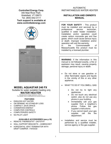
AUTOMATICINSTANTANEOUS WATER HEATERControlled Energy Corp.340 Mad River ParkWaitsfield, VT 05673Tel. (800) 642-3111Tech support is available atwww.controlledenergy.comINSTALLATION AND OWNER’SMANUALFOR YOUR SAFETY - Thisproduct must be installed and servicedby a professional service technician,qualified in water heater installation.Installation and/or operation couldcreate carbon monoxide gas and fluegases, which could cause seriousinjury or death. Improper installationand/or operation will void the warranty.In the Commonwealth of Massachusettsthis product must be installed by alicensed plumber.WARNING : If the information in thismanual is not followed exactly, a fire orexplosion may result, causing propertydamage, personal injury or death.MODEL AQUASTAR 240 FX Do not store or use gasoline or otherflammable vapors and liquids in thevicinity of this or any otherappliance. WHAT TO DO IF YOU SMELL GASSuitable for water (potable) heating only WATER HEATERManufactured by Takagi Industrial Co. USA Inc.The Aquastar name is trademarked and licensed by Bosch. FEATURESENDLESS HOT WATERON DEMAND, NO STAND-BY LOSSCOMPACT, SAVE SPACECONSERVES ENERGYCOMPUTER CONTROLSCOMPUTERIZED SAFETYNO PILOT LIGHT AVAILABLE ACCESSORIES (see p.16)REMOTE THERMOSTAT – 240TSTATHORIZONTAL VENT TERMINATOR WITHDRAFT DAMPER - FXHOOD 1Do not try to light anyappliances.Do not touch any electricalswitch, also do not use anyphone in your building.Immediately call your gassupplier from a neighbor’sphone. Follow the gassupplier’s instructions.If you cannot reach your gassupplier,callthefiredepartment.Installation and service must beperformed by a qualified installer,service agency or the gas supplier.
TABLE OF CONTENTSFor Your Safety . 3Operation . 4 . 4 . 4 . 4 .4 & 22. . . 4 . 5GeneralNormal OperationStart UpTemperatureFreeze PreventionWinterizingInstallation SPECIFICATIONSNatural Gas InputMin. 37,000 BtuMax. 165,000 BtuLP Gas InputMin. 35,000 BtuMax. 165,000 BtuGas Connection¾” NPTWater Connections¾” NPTWater PressureMin. 15 psiMax. 150 psi . 5Natural Gas Pressurebefore appliance:General . 5Outdoor Installation . 6Indoor Installation . 7High Altitude . 7Combustion Air . .8Venting . .8Manufactured Home (Mobile home) andRecreation Park Trailer Installation .10Gas Supply . 10Water Connections . 12Pressure Relief Valve . 12Electrical Connection . 13Wiring Diagram . 14LP Gas Pressurebefore appliance:Min. 11” WCMax. 14” WCManifold Pressure*Natural 3.5” WCLP Gas 4.0” WC*measured with a maximum hot water flow rate (5.3gallon per minute)WeightDimensions60 lbs.24 ½” x 16 ½” x 8 ¼”IgnitionInitiating the Heater . 15Accessories .16 . 17Common Questions . 17Part List . 21Electronic IgnitionElectrical SupplyAC 120 Vless than 2 amp***Maintenance and Service . 17Trouble ShootingMin. 5” WCMax. 10.5” WC 2Inlet gas pressure before appliancemust not exceed above value.For gas pressures lower than 5” WC forNatural Gas or 11” WC for LPG, do notinstall until gas pressure is corrected.Check the rating plate to insure thisproduct matches your specifications.High Altitude installations: see p.7Takagi - USA is constantly improving itsproducts, therefore specifications aresubject to change without prior notice.
FOR YOUR SAFETYwarm or mild climates. Locations with wintertemperatures that regularly drop below freezingare not recommended. Refer to the section onWinterizing and Freeze Prevention Device formore information.PLEASE, READ CAREFULLY THIS MANUAL ANDFOLLOW IT FOR YOUR SAFETY.1.2.3.4.5.Follow all local codes, or in the absence oflocal codes, follow the most recent editionof the National Fuel Gas Code, ANSIZ223.1/NFPA 54 in the USA.Properly ground the unit in accordance with alllocal codes or in the absence of local codes,with the National Electrical Codes, ANSI/NFPA70 in the USA.Carefully plan where to install water heater.Correct combustion air supply and flue pipeinstallation are very important. If not installedcorrectly, fatal accidents can be caused by lackof air, carbon monoxide poisoning or fire.Locate water heater where water leakage willnot do damage to surrounding areas. If there isa possibility of water damage install a suitabledrain pan under the unit that will not restrictcombustion air.National Fire and Building Codes do not allow agas fired water heater installation in abathroom, bedroom or any occupied roomnormally kept closed. The place where youinstall the heater must have enough ventilation.Check the rating plate for the correct gas type,gas pressure, water pressure, and electricalrating before installing it.Rating plate6.7.If any problem should occur, turn off all hotwater taps and turn off the gas. Then call atrained technician, the Gas Company orControlled Energy.WARNING : Do not disconnect the electricalsupply if the temperatures will be near freezing.The Freeze Prevention Device only works if theunit has proper electrical power. In outdoorinstallations the Freeze Prevention Device israted for temperatures down to 5ºF (-15ºC) in awind free environment. The wind chill factor willcause the AQ240FX Water Heater to freezeand be damaged at temperatures above 5ºF(-15ºC). Due to this we strongly recommendthat the 240FX only be installed outside in38.WARNING : Before bathing or showeringalways check the water temperature. Donotleavechildrenortheinfirmunsupervised in the shower or bath. Thewater temperature is set at 122ºF (50ºC)from the factory to maximize the amount ofhot water you can use. See p.49.WARNING : Do not use this appliance ifany part has been underwater. Immediatelycall a certified gas technician to inspect andservice the unit if necessary.10.WARNING : Do not store or use gasoline orother flammable vapors and liquids in thevicinity of this or any other appliance.11.WARNING : Do not reverse the water andgas connections as this will damage thewater heater and can cause severe injuryor death from scalds. Follow the diagrambelow when installing the AQ240FX waterheater.12.WARNING : The heater may still operatewhen improperly installed. It will, however,be less efficient and could eventuallydamage the heater. It could even result inhuman sickness or death due to oxygendeprivationandcarbonmonoxidepoisoning.
OPERATION2.“Fire On” lamp extinguished, the exhaust fanwill continue to operate for 70 seconds.GeneralThe AQ240FX Water Heater is an instantaneous,tankless water heater designed to supplyhousehold and commercial hot water with totalefficiency. The principle behind the AQ240FX WaterHeater is simple. Once you open a hot water tap,water flows through the water heater. The waterflow sensor signals the computer to electronicallyignite the burners and the computer monitors thewater temperature, volume of water, and gas flowthe insure you get the right amount of hot water.After the burners are ignited the “fire on” lamp is lit.Start UpOnce the unit has been properly installed, check thegas and water connections for leaks. Check forproper ventilation and combustion air to the heater.Purge the gas and water lines to remove debris.Then follow these steps to turn on your unit.1.2.3.The burners activate at a .75 gallon per minute flowrate. After the burners are ignited, the flow rate canbe lowered to 0.6 gallons per minute to maintain theheater on.Now as long as you have water, adequate gassupply and electricity, you will get an endless flowof hot water. Open a hot water tap to turn on thewater heater. Close the tap to turn off the waterheater.4.5.TemperatureThe 240FX has been set at the factory to deliver122º F (50º C) water. This is electronicallycontrolled by the computer. When drawing hotwater, mix with cold water if necessary to get adesired temperature.See degree rise table on page 22.Normal OperationTo Turn on water heater1. Open a hot water tap.2. Burners ignite, “Fire On” lamp is lit and theexhaust fan operates.3.Mix with cold watertemperature water.togettheClose the manual gas control valve located onthe gas line.Fully open the manual water control valve onthe water supply line.Open a hot water tap, to verify that water willflow to that tap. Then close the hot water tap.Fully open the manual gas control valveinstalled.Turn on the 120 volt 60 Hz power supply to thewater heater.WARNING : Temperatures above 125º F (52º C)can cause severe burns or death from scalding.Children, the disabled and the elderly are at highrisk of being injured. Feel the water temperaturebefore bathing or showering. Do not leave children,disabled, and the elderly unsupervised.The inlet water temperature will dictate howmuch hot water you can produce, but you willnot be able to produce more than 5.3 gallonsper minute of hot water because there is a flowgovernor restricting the water flow.correctFreeze Prevention DevicesThis unit comes equipped with heaters thatdiscourage the unit from freezing in an outdoorTo Turn off your water heater1. Close the hot water tap4
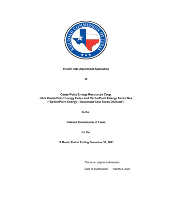
installation. For this freeze prevention system tooperate there has to be electrical power to the unit.The freeze prevention devices will not work ifthe electrical power source is disconnected. Theunit has been rated for temperatures down to 5º F(-15º C) in a wind free environment. The wind chillfactor will cause the unit to freeze at temperaturesabove 5º F (-15º C). Due to this we stronglyrecommend that the 240FX only be installedoutside in warm or mild climates. Locations withwinter temperatures that regularly drop belowfreezing are not recommended. Do not install thewater heater in an area with extremely coldweather. This will void your warranty andControlled Energy will not be responsible for anydamage that occurs.CAUTION : The pipe heaters are located on theAQ240FX Water Heater only. Any hot or coldwater pipes located outside of the unit will notbe protected. Properly protect and insulatethese pipes from freezing.1.2.3.4.5.6.Make sure all hot water taps are closed and thedrain plugs are securely attached.Purge the water line of debris.Turn on the manual water control valve locatedon the water supply line.Open all the hot water taps to verify water flowsto the taps. Then close hot water taps.Turn on the manual gas control valve locatedon the gas supply line.Turn on the power supply to the AQ240FXWater Heater.Supplied by installerControlled Energy strongly recommends theuse of its CSA approved vent terminator with abuilt in back draft flapper for any Horizontallyvented indoor installations where outsidetemperatures will be below freezing. Without itnegative air can freeze the copper heatexchanger in the AQ240FX when not in use. Ifthis type of vent terminator was not purchasedwith the heater and you are in a cold climate,please contact your distributor or ControlledEnergy to order. Item FXHOODFig. AWinterizingINSTALLATIONIf you will not be using your heater for a long periodof time or if the temperatures will drop below 5º F(-15º C) with the wind chill factor, turn off yourheater and drain the unit of water. This will keepyour unit from freezing and being damaged. Followthese instructions carefully:1. Turn off the power supply to the Water Heater.2. Turn off the manual gas shut off valve locatedoutside your heater.3. Turn off the manual water shut off valve locatedon the water supply line. See Fig. A4. Open all hot water taps in the house.(Bathroom, kitchen, laundry room, etc.). Whenthe water flow has ceased, close all hot watertaps.5. Have a bucket or pan to catch the water fromthe units drain plugs. Remove the drain plugs todrain all the water out of the unit.6. Leave for 5 minutes.7. Securely screw the drain plugs back into place.Please keep this owner’s manual in a safeplace for future reference. Copies of thismanual are available from Controlled EnergyThis section is for the installer. Theinstaller is responsible for the correctinstallation of your AQ240FX WaterHeater.For Your Safety : Only a gas technicianor qualified plumber may service orinstall your product.GeneralAll gas water heaters require careful and correctinstallation to insure safe and efficient operation.This manual must be followed exactly.1. Read the For Your Safety section in thebeginning of this manual.Now when you want to use your heater again followthese steps:5
2.3.4.5.6.7.8.9.This unit is not capable of being used as a poolor spa heater, nor is it certified for spaceheating.The internal gas regulator is preset at thefactory. It is computer controlled and should notneed adjustment. Do not supply unit with inletgas pressure that exceeds the specifiedmaximum amount on page 2 of this manual.Suitable for potable water heating only.Maintain proper space for servicing. Install theunit so that it can be connected or removedeasily.The electrical connection requires a means forswitching off the power supply.Avoid installing the unit in an area with highlevels of dust, sand or debris. Impure particlesfrom these objects may clog the air vent orreduce functions of the rotating fan and causeincomplete combustion.Do not install the unit where the exhaust vent ispointing into any opening in a building. Forhorizontally vented installations: Do not installexhaust vent against vinyl siding. Allowexhaust vent to mount flush to a non plasticsurface such as pine board or plywood andmaintain at least a 3 inch clearance from thevinyl.The 240FX can be wall supported Indoors orOutdoors using the 240BRACKET accessory.See page 13. These wall support brackets areare supplied with the heater and are requiredwhen wall hanging. Floor mounted installationsrequire use of the smaller Wall Mount Brackets.See pages 6-7 and table below. Additionalstrapping to prevent tipping or falling inearthquake-prone zones may be required.Check local codes.OUTDOOR INSTALLATIONFollow all local codes and in the absence oflocal codes, follow the National Fuel Gas CodeANSI Z221.23 in the USA.Locate the water heater in an open, unroofed area,and maintain the following minimum clearancesfrom combustible and noncombustible materials.Piping sideFront (Maintenancespace)FloorBack of heaterNon piping sideTop of heater12”24”Non combustiblebase Min. 3” off theground1”6”36”Do not install this water heater under an overhang,less than 3 feet from its top. The area under anoverhang must be open to three sides.Included AccessoriesCheck that all parts listed below were included withthe unit. (2) wall support brackets are also included.When installing the AQ240FX on a placementstand, be sure to adjust the legs so that it standslevel and secure. (Adjustable legs can be moved upto 1”)Pressure Relief ValveUse the two L shaped Wall Mount Brackets tosecurely attach the AQ240FX to a wall surface. Usea screw to attach the longer part of the wall mountbracket temporarily to the heater and determinescrew positions on the wall. Then drill a ¼” hole inthe wall. Insert anchor. Tighten all 4 screws.Minimum clearance behind the heater is 1”.6
WARNING: Improper installation can cause nauseaor asphyxiation from carbon monoxide and fluegases which could result in severe injury or death.FOR HIGH ALTITUDE INSTALLATIONS ABOVE5,000 FEETThe btu output of the AQ240FX will be reduced 4%for each 1,000 feet over 5,000 feet. The computeroperation of the heater properly monitors the btuoutput and combustion quality of the heater up to a5,000 foot elevation. Above 5,000 feet this willresult in lower degree rise. For installations above10,000 feet please contact CEC.WARNING : Do not have the flue terminal pointingtoward any opening into a building. Do not locateyour heater in a pit or location where gas and watercan accumulate.INDOOR INSTALLATIONMounting the heater: Review mounting bracketoptions in section 9 on page 6.Follow all local codes and in the absence oflocal codes, follow the National Fuel Gas CodeANSI Z221.23 in the USA.FOR INDOOR INSTALLATION REMOVEOUTDOOR VENT CAP AND CUTPRESSURE SWITCH JUMP WIRE THENINSTALL 4” VENTING DIRECTLY ONFLUE OUTLET. : PLEASE! Look insideunit.WARNING : Do not install the heater where water,debris, or flammable vapors may get into the flueterminal. This may cause damage to the heater.See p. 13 for Fan PressureSwitch location in heaterWARNING : Do not install the heater with the ventwithin 4 feet of any opening into a building.For indoorinstallations only, cutthis wire. Be sure toplace wire nuts onthe cut ends. Oncecut, this safetypressure switch willbe ready to shut theheater off if the unitis inadequately orimproperly venting.ClearancesPiping sideFront (Maintenancespace)FloorBack of heaterNon piping sideTop of heater7Min. 6”Max. 24”Min. 4”Noncombustiblebase1”Min. 2”11”
Combustion Air SupplyINSIDE AIR SUPPLY; when combustion air issupplied from inside the building. Each opening ofthe closet door should have a minimum free area ofone square inch per 1000 BTUH input of the totalinput rating of all appliances in the enclosed area.The water heater location must be provided with aproper amount of combustion air. See the latestedition of ANSI Standard Z223.1 and any localcodes that are applicable.DO NOT INSTALL DIRECTLY ON CARPETING.In general these requirements specify that if the unitis installed in a confined space there must bepermanent air supply openings.Minimum size of open space required for 240FXWater heatersize165,000BTUVolume8,250 CubicFt.Area with an8 Ft. ceiling1,031Square Ft.If the 240FX is installed in an area smaller thanindicated above, then the installer must makespecial provisions for combustion air in the form oftwo openings, one within 12” of the top and onewithin 12” of the bottom of the space, each having atotal free area of 1 square inch per 1,000 BTUH ofrated input if the air is taken from inside the house.This requirement reduces to 1 square inch per4,000 BTUH if the air is taken from the outside.See the National Fuel Gas Code for alternatemethods.Air Vents(165 sq. in. each)VENTINGThis water heater must be vented in accordancewith Venting of Equipment, of the latest edition ofthe National Fuel Gas Code.WARNING : Improper venting of this appliance canresult in excessive levels of Carbon Monoxidewhich can result in severe personal injury or death.OUTSIDE AIR SUPPLY; when combustion air issupplied directly through an outside wall, such asintake louver openings into the dwelling. Eachopening should give a minimum free area of onesquare inch per 4000 BTUH input of the total inputrating of all combustion appliances in the enclosedarea.240FX240FXVent ConnectionsThis water heater is listed for use with single wallstainless (AL29-4C) and must maintain a 3”clearance to combustibles. Use of a special gasvent listed for Type II, III and IV is required.Manufacturers include FasNSeal, Z-Flex and HeatFab. Follow clearances and sealing methodsspecified by those manufacturers. If local codessupercede national codes (NFGC and IFGC), agreater clearance to combustibles may be required.Always check with your local plumbing ormechanical inspector before installing.The vent system must be gas tight. All seams andjoints must be sealed with silicone sealant that hasa minimum temperature rating of 350º F, unless thevent pipe is constructed with its own gasket. Forbest results, horizontal and vertical vent systemsshould be as short and straight as possible.Air Vents(42 sq. in. each)Double wall type B-vent is not permitted orapproved for venting this water heater.Do not common vent the 240FX with any othervented appliance.8
The entire vent system must not exceed the specifications in the following table.DiameterMax. No. ofElbow4”3 Ea.Max.Vertical orHorizontalrun inLength21 ftSubtract 5 feet for each elbow. Example: 11 ft. is the maximum totaldistance if two elbows are used.When the horizontal vent run exceeds 5 ft. the following criteria must be observed; Attach a vertical pipe at least 2” high to the water heater outlet before the horizontal run. Support the vent run at 3 ft intervals with overhead hanger. Pitch up the vent run toward the vent terminal at a rate of 1/ 4” per foot.If Horizontally Venting:A listed side wall vent terminator must be used when the water heater is vented through a side wall. TheFXHOOD is recommended. The terminator provides a means of installing vent pipe through the building walland must be located in accordance with ANSI Z223.1 and local applicable codes. See page 5 for indoor freezeprevention and recommended vent terminator to be used.Side wall exit locations for mechanical draft vent terminals9
GAS SUPPLY AND PIPINGIf Vertically Venting:Follow the vent length specifications in table onpage 9 and use a listed vent cap.This unit requires a gas control shut-off valve to besupplied by the installer. It must be placed on theunit before it is connected to the gas line.Check that the gas inlet pressure and the type ofgas matches the rating plate located on your waterheater. Insufficient gas pressure will cause yourAQ240FX Water Heater to be inefficient and notwork properly. Size the gas piping correctly.MANUFACTURED HOME( MOBILE HOME ) andRECREATIONAL PARK TRAILERSWARNING : Read and Review this entire Manualwith special emphasis on the Combustion andVentilation for your safety.For up to 25ft. ¾” Black Iron pipe is theminimum pipe size required for Natural Gas.This appliance must be installed in accordance withthe Manufactured Home Construction and SafetyStandard (Title 24, CFR ; Part 3280 ) and ANSIA119.5 for Recreational Park Trailers, the followinginstructions supplied with the vent termination, localcodes and utility company requirements governingthe installation of water heaters in manufacturedhome ( mobile home ) and Recreational ParkTrailers and/or in the absence of local codes, thelatest edition of the National Fuel Gas Code, ANSIZ 223.1/NFPA 54 and ANSI A119.5/NFPA 501D.For up to 25ft. ½” Black Iron is the minimumpipe size required for LP.Location for a Manufactured Home (MobileHome) and Recreational Park TrailersMinimum and maximum inlet gas pressures are asfollows:For up to 10ft. 5/8” Copper is the minimum pipesize required for LP.Flex lines are not recommended, oversize if oneneeds to be used.See Gas Sizing tables on page 11.This water heater must be installed within anenclosure to separate the water heater’scombustion and venting system from the interioratmosphere of the manufactured home or trailer. Allair for combustion must be obtained from theoutside atmosphere. And the products ofcombusted gases ( flue gases ) must be dischargeddirectly to the outside through the gas vent. Theremust not be any door or other opening into thewater heater enclosure from the inside of themanufactured home. Please refer to installationdiagrams and freeze protection informationNatural GasPropane GasMin. 5” WCMax. 10.5” WCMin. 11” WCMax. 14” WCMaximum gas pressures must not exceed thisvalue.After the connections are complete check for gasleaks by applying soapy water to all gas fittings andconnections. Soap bubbles are a sign of gas leaks.This appliance must be isolated from the gas supplypiping system by unplugging the unit anddisconnecting the main gas during any pressuretesting of the gas supply piping system at testpressures equal to or more than ½ Psi. Theappliance and its gas connections must be leaktested before placing the unit in operation.Always use approved connectors to connect theunit to the gas line. Always purge the gas line ofany debris before connection to the heater.WARNING: Conversion of this unit from natural gasto propane or propane to natural gas cannot bedone. Contact your local retailer or distributor to getthe correct unit for your gas type.Placement of Water Heater: Locate the waterheater as desired, make certain the minimumclearances are maintained. For indoor installationfollow page 7-9, and outdoor installation follow page6-7, please see section for manufactured home andrecreational park trailer outdoor installation.Indoor installation for a Manufactured Home(Mobile Home) and Recreational Park TrailersSame as typical house installation except, all air forcombustion must be obtained from the outsideatmosphere for manufactured home.Please see page 8 for indoor installation.10
Check the rating plate to make sure that the unit is labeled for the type of gas available in the area.The gas supply piping should be sized according to the Applicable Plumbing Code for a maximum drawof 165,000 BTUH. First determine the effective length of the gas supply line by measuring the actuallength of piping, and then adding 5 ft. for every elbow or “T” to the actual length. Use the charts belowto determine the pipe diameter necessary to accommodate the BTU demand of the unit. If there aremore gas drawing appliances on the line, size according to the maximum amount of BTU demand.Natural Gas Supply Piping (Black Iron) – inside diameterBased on 0.60 specific gravity for natural gas at .5” WC pressure dropDOE standard is 1100 BTU per cubic ft. of natural gasBtu numbers given in thousandsPipeSizeCubic Feet of Natural GasLength 1329273635650¾”278190 152 130 115 105961”520350 285 245 215 195 180 170 1601 ¼” 1050 730 590 500 440 400 370 350 3201 ½” 1600 1100 890 760 670 610 560 530 4902”3050 2100 1650 1450 1270 1150 1050 990 0380710200’100210320610Propane Supply Piping (Black Iron) – inside diameterBased on 11” WC supply pressureBtu numbers given in thousandsPipeSizeLength½”¾”1”1 ¼”1 ½”2”kBTU of �� 100’ 125’ 150’ 200’275 189 152 129 114 103567 393 315 267 237 217 196 185 173 162 146 132 1121071 732 590 504 448 409 378 346 322 307 275 252 2132205 1496 1212 1039 913 834 771 724 677 630 567 511 4403307 2299 1858 1559 1417 1275 1181 1086 1023 976 866 787 6756221 4331 3465 2992 2646 2394 2205 2047 1921 1811 1606 1496 1260Propane Supply Piping (Copper) - outside diameterBased on 11” WC supply pressureBtu numbers given in ��138
PRESSURE RELIEF VALVEWater ConnectionsThis unit is supplied with a listed pressure reliefvalve. The pressure relief valve must be installed onthe hot water outlet. A “Tee” fitting should be usedto attach the pressure relief valve.The pressure relief valve must not exceed thefollowing:A listed manual water control valve must be placedon the cold water supply line. All soldering materialsand piping materials must be useable with potablewater. Don’t solder connections close to the heater.If the water heater is installed in a closed watersystem, such as one having a backflow preventer inthe cold water supply line, means shall be providedto control thermal expansion, such as a smallexpansion tank.Purge the water line to remove all the debris and airfrom it. It may damage the heater if you do not.There is a wire mesh filter to discourage debris fromentering your heater. This will need to be cleanedperiodically.Pressure Relief150 psiThe discharge capacity must be at least 165,000Btu/hr and the discharge opening shall be piped toa suitable drain to prevent water damage shoulddischarge occur.If the pressure relief valve on the appliancedischarges periodically, this may be due to thethermal expansion in a closed water supply systemor excessive building water pressure. Contact thewater supplier or local plumber on how to correctthis situation.Do not plug the pressure relief valve. The relief lineshould have no reduced fittings or other restrictionsand should allow for complete drainage of valveand line. The pressure relief valve must bemanually operated once a year to check for correctoperation.Should overheating occur or gas supply fail to shutoff, turn off the manual gas control shut-off valve tothe appliance.WARNING : Do not reverse the hot outlet and coldsupply line connections to the AQ240FX. This willcause your heater to operate dangerously. Makesure the hot and cold lines are connected properly.Refer to the FOR YOUR SAFETY section at thefront of this manual.PressureRelieve ValveHot water supplyto building12
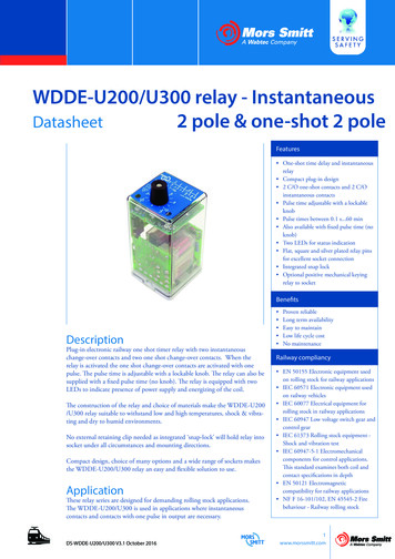
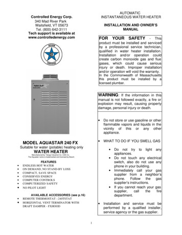
Electrical ConnectionsWARNING : The heater must be electricallygrounded in accordance with the most recentedition of the National Electrical Code, ANSI/NFPA70. Do not rely on the gas or water piping to groundthe metal parts of the heater.CAUTION : Label all wires prior to disconnectionwhen servicing controls. Wiring error can causeimproper and dangerous operation. Verify properoperation after servicing.The AQ240FX requires an electrical power supplyfrom 120 VAC 60 Hz circuit and must be properlygrounded. A means for switching off the 120 VAC powersupply must be provided. Wire the heater exactly as shown in the wiringdiagram on page 14 and Fig B.A green screw is provided in the junction boxfor grounding connection.Fig. BRefer to the wiring diagram. A wiring diagram isalso located on the inside panel of the appliance.Hi-Limit switchUpper OnLampLower stand -by lamplook into this opening at a45 degree angle from theright to properly view thislampBurner ViewWindowInlet Filter ScreenFlowSensorGFCIFan PressureSwitch13
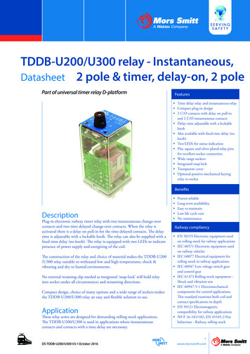
Wiring Diagram: wiring diagram is also located on the inside panel of the appliance.Electrical Rating120 VAC, 60 Hz, 0.8 ANote: If any of the original wiring supplied with this appliance must be replaced, it must bereplaced with appliance wiring material (180c) or its equivalent. Wires are available throughthe manufacturer.14
Initiating the HeaterOperating InstructionsFor your safety read before operating.1. STOP! Read the safety information first!2. Turn off electric power to the appliance.3. Do not attempt to light the burnermanually.4. Turn the manual gas control valvelocated outside of the unit on the gasline counterclockwise to the closedposition.5. Wait five (5) minutes to clear out anygas. If you then smell gas, STOP!Follow “B” in the safety informationabove on this section. If you do notsmell gas go to the next step.6. Turn the manual gas control valvelocated outs
Controlled Energy Corp. 340 Mad River Park Waitsfield, VT 05673 Tel. (800) 642 -3111 Tech support is available at www.controlledenergy.com . The AQ240FX Water Heater is an instantaneous, tankless water heater designed to supply household and commercial hot water with total efficiency. The principle behind the AQ240FX Water