Transcription
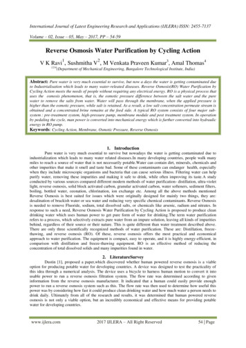
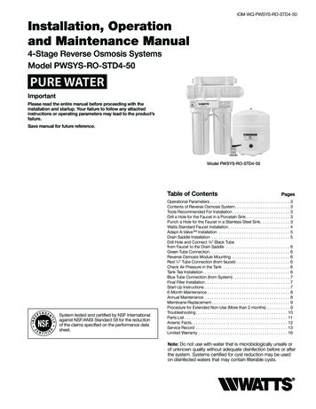
IOM-WQ-PWSYS-RO-STD4-50Installation, Operationand Maintenance Manual4-Stage Reverse Osmosis SystemsModel PWSYS-RO-STD4-50PURE WATERImportantPlease read the entire manual before proceeding with theinstallation and startup. Your failure to follow any attachedinstructions or operating parameters may lead to the product’sfailure.Save manual for future reference.Model PWSYS-RO-STD4-50Table of ContentsSystem tested and certified by NSF Internationalagainst NSF/ANSI Standard 58 for the reductionof the claims specified on the performance datasheet.PagesOperational Parameters . . . . . . . . . . . . . . . . . . . . . . . . . . . . . . . . . . . 3Contents of Reverse Osmosis System . . . . . . . . . . . . . . . . . . . . . . . . 3Tools Recommended For Installation . . . . . . . . . . . . . . . . . . . . . . . . . 3Drill a Hole for the Faucet in a Porcelain Sink . . . . . . . . . . . . . . . . . . . 3Punch a Hole for the Faucet in a Stainless Steel Sink . . . . . . . . . . . . . 3Watts Standard Faucet Installation . . . . . . . . . . . . . . . . . . . . . . . . . . . 4Adapt-A-Valve Installation . . . . . . . . . . . . . . . . . . . . . . . . . . . . . . . . 5Drain Saddle Installation . . . . . . . . . . . . . . . . . . . . . . . . . . . . . . . . . . . 5Drill Hole and Connect 3 8" Black Tubefrom Faucet to the Drain Saddle . . . . . . . . . . . . . . . . . . . . . . . . . . . . . 6Green Tube Connection . . . . . . . . . . . . . . . . . . . . . . . . . . . . . . . . . . . 6Reverse Osmosis Module Mounting . . . . . . . . . . . . . . . . . . . . . . . . . . 6Red 1 4" Tube Connection (from faucet) . . . . . . . . . . . . . . . . . . . . . . . . 6Check Air Pressure in the Tank . . . . . . . . . . . . . . . . . . . . . . . . . . . . . . 6Tank Tee Installation . . . . . . . . . . . . . . . . . . . . . . . . . . . . . . . . . . . . . . 6Blue Tube Connection (from System) . . . . . . . . . . . . . . . . . . . . . . . . . 7Final Filter Installation . . . . . . . . . . . . . . . . . . . . . . . . . . . . . . . . . . . . . 7Start Up Instructions . . . . . . . . . . . . . . . . . . . . . . . . . . . . . . . . . . . . . . 76-Month Maintenance . . . . . . . . . . . . . . . . . . . . . . . . . . . . . . . . . . . . 8Annual Maintenance . . . . . . . . . . . . . . . . . . . . . . . . . . . . . . . . . . . . . . 8Membrane Replacement . . . . . . . . . . . . . . . . . . . . . . . . . . . . . . . . . . 9Procedure for Extended Non-Use (More than 2 months) . . . . . . . . . . . 9Troubleshooting . . . . . . . . . . . . . . . . . . . . . . . . . . . . . . . . . . . . . . . . 10Parts List . . . . . . . . . . . . . . . . . . . . . . . . . . . . . . . . . . . . . . . . . . . . . 11Arsenic Facts . . . . . . . . . . . . . . . . . . . . . . . . . . . . . . . . . . . . . . . . . . 12Service Record . . . . . . . . . . . . . . . . . . . . . . . . . . . . . . . . . . . . . . . . . 13Limited Warranty . . . . . . . . . . . . . . . . . . . . . . . . . . . . . . . . . . . . . . . 16Note: Do not use with water that is microbiologically unsafe orof unknown quality without adequate disinfection before or afterthe system. Systems certified for cyst reduction may be usedon disinfected waters that may contain filterable cysts.
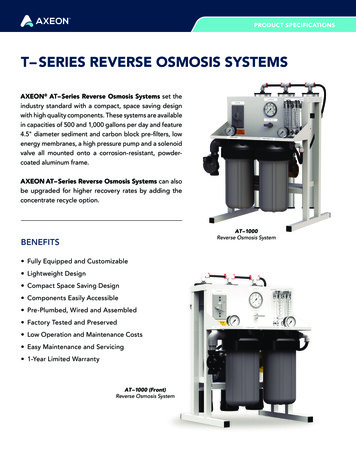
IntroductionSystem MaintenanceJust because you can not taste it, does not mean that it is not there.Contaminants such as lead, chromium and arsenic (to name a few)are undetectable to the taste. Additionally, over time if you do notreplace the filter element, other bad tastes and odors will be apparent in your drinking water.Thank you for your purchase of a state of the art Watts PureWater Reverse Osmosis (RO) water treatment system. Waterquality concerns are becoming more of a focus for the public. Youmay have heard about contaminants in the drinking water, such asArsenic, Chromium, Cryptosporidium or Giardia. There may also besome local water issues such as high levels of Lead and Copper.This Watts Pure water treatment system has been designed andtested to provide you with high quality drinking water for years tocome. The following is a brief overview of the system.This is why it is important to change out your filter at the recommended intervals as indicated in this system manual. When replacingthe filter elements, pay special attention to any cleaning instructions.Should you have any further questions please refer to our websiteat www.watts.com or call our customer service department at1-800-244-1299.Your Reverse Osmosis System:Osmosis is the process of water passing through a semi-permeablemembrane in order to balance the concentration of contaminantson each side of the membrane. A semi-permeable membrane is abarrier that will pass some particles like clean drinking water, but notother particles like arsenic and lead.With proper installation and maintenance, this system will provideyou with high quality water for years to come. All of Watts waterenhancement products are rigorously tested by independent laboratories for safety and reliability. If you have any questions or concerns,please contact our Customer Service department at 1-800-2441299 or refer to our on-line troubleshooting at www.watts.com.Reverse osmosis uses a semi-permeable membrane; however, byapplying pressure across the membrane, it concentrates contaminants (like a strainer) on one side of the membrane, producing crystalclear water on the other. This is why RO systems produce both cleandrinking water and waste water that is flushed from the system. Thisreverse osmosis system also utilizes carbon block filtration technology and can, therefore, provide a higher quality drinking water thancarbon filtration systems alone.Your system is a 4-Stage RO which is based upon separate treatment segments within the one complete water filtration system.These stages are as follows:Stage 1 – Sediment filter, recommended change 6 months.(See Page 8).The first stage of your RO system is a five-micron sediment filter that traps sediment and other particulate matterlike dirt, silt and rust which affect the taste and appearance of your water.Stage 2 – Carbon filter, recommended change 6 months.(See Page 8).The second stage contains a five-micron carbon blockfilter. This helps ensure that chlorine and other materialsthat cause bad taste and odor are greatly reduced.Stage 3 - Membrane, recommended change 2-5 years.Stage 3 is the heart of the reverse osmosis system, theRO membrane. This semi-permeable membrane will effectively take out TDS, sodium and heavy metals such asarsenic, copper, and lead, as well as Cysts, such as Giardia and cryptosporidium. Because the process of makingthis high quality drinking water takes time, your RO watertreatment system is equipped with a storage tank.Stage 4 - Carbon in-line filter, recommend change 6 - 12months.The final stage is an in-line granular activated carbon(GAC) filter. This filter is used after the water storage tank,and is used as a final polishing filter.Note: F ilter & Membrane life may vary based upon local waterconditions and/or use patterns.Replacement Filter PacksModelFrequencyDescriptionIncludes sediment and carbonfilter onlyPWFIL-4PACK-STD-ZRO4AnnualIncludes all filters and membranePWFIL-MEM-STD-50GPD2 - 5 years50 gpd membranePWFIL-GAC-IL-10Annual10" final in-line filterNote: Water conditions may require more frequent cartridge replacementPWFIL-2PACK-STD-WG/ZW6 Months2
STEP 1Operational ParametersDrill a Hole for the Faucet in a Porcelain SinkDo not use with water that is microbiologically unsafe or ofunknown quality without adequate disinfection before or afterthe system. System is intended to be installed on the cold waterline only.Operating TemperaturesOperating PressurepH ParametersIronTDS (Total Dissolved Solids)TurbidityMaximum 100 F (37.8 C)Maximum 85psi(6.0 kg/cm2)Maximum 11Maximum 0.2 ppm 1800 ppm 5NTUNote: Most sinks are predrilled with 1½" or 1¼" diameter holethat you can use for your RO faucet. (If you are already using itfor a sprayer or soap dispenser, see Step 2).Minimum 40 F (4.4 C)Minimum 40psi(2.80 kg/cm2)Minimum 2Caution: Porcelain sinks are extremely hard and can crack orchip easily.Use extreme caution when drilling. Watts accepts no responsibility for damage resulting from the installation of faucet.Step A – Determine desired locationfor the RO faucet on your sinkand place a piece of maskingtape on over where the hole isto be drilled. Mark the centerof the hole on the tape.Hardness: Recommended hardness not to exceed 10 grains pergallon, or 170ppm. System will operate with hardness over 10 grainsbut the membrane life may be shortened. Addition of a water softener may lengthen the membrane life.Step B – Using a variable speed drillset on the slowest speed, drilla 1 8" pilot hole through bothporcelain and metal casingof sink at the marked centerof the desired location. Uselubricating oil or liquid soapto keep the drill bit cool (If drillbit gets hot, it may cause theporcelain to crack or chip).Water Pressure: The operating water pressure in your home shouldbe tested over a 24-hour period to attain the maximum pressure.If the incoming water pressure is above 85psi, a pressure regulator is recommended and if over 100psi, then a pressure regulator isrequired.Copper Tubing: Reverse Osmosis water should not be run throughcopper tubing as the purity of the water will leach copper causingan objectional taste in water and pin holes may form in the tubing.Watts supplies speciality filters that can be used if copper tubingfollows the Reverse Osmosis unit. Be sure to follow any state or localregulations during installation.Step C – Using a 1¼" hole saw, proceed to drill the large hole.Keep drill speed on the slowest speed and use lubricatingoil or liquid soap to keep thehole saw cool during cutting.Contents of Reverse Osmosis (RO) SystemStep D – Make sure the surroundingsof the sink are cooled beforemounting the faucet to thesink after drilling and removeall sharp edges.1 Tank – Blue or White1 RO Module1 Parts Bag – With a 10" Final Filter1 Faucet Bag1 ManualIf any of the items are missing please contact prior to installing.ORPunch a Hole for the Faucet in a StainlessSteel SinkTools Recommended for Installation 1¼" Hole Saw Bit for Faucet openingNote: If mounting faucet to a StainlessSteel Sink, you will need a 1¼" HolePunch. The faucet opening should becentered between the backsplash andthe edge of the sink, ideally on thesame side as the vertical drain pipe. Round Knockout Punch for StainlessSinks 1¼" Adjustable Wrench Sharp Knife 1 2" & 5 8" Open End WrenchesStep A – Drill a ¼" pilot hole. Use a 1 2"Hole Punch and an adjustablewrench to punch the hole in thesink. Change to the 1¼" HolePunch to enlarge the hole Phillips Screw Driver Needle Nose Pliers – Adjustable Pliers Electric Drill 1 8" Drill Bit 1 4" Drill BitThe faucet can now be installed. 3 8" Drill Bit3
Standard Faucet InstallationSTEP 21. Faucet2. Gravity Drainline (3 8" Black)3. Red Line4. Escutchean Plate5. Full Circle Rubber Gasket6. Slotted Rubber Washer7. Slotted Metal Washer8. Plastic Spacer or Sleeve9. Hex Nut Washer10. White Plastic Delrin Sleeve11. Water Line Connect or Nut12. Blue Water Line13. Turn 212Sink TopUnder SinkExploded View1. List of Parts and Assembly in Exploded ViewAir Gap Hole(See Note).BlackGravity Drain Line(See Important)RedBlue2. Complete Assembly3. Close-up Assembly and Important NoticeStep A – Remove nut (Item 11) and blue tubing (Item 12) fromfaucet. (Leave the nut and plastic delrin sleeve (Item 10) onthe blue tube).Step B – Feed both the red and black tubing through the pre-drilledhole in the sink/counter until faucet is seated.Step C – Under the sink - on to the threaded faucet stem in orderfirst slide on the rubber gasket (Item 6), the slotted washer(Item 7), the white spacer with the open end UP (Item 8),the hex nut washer (Item 9), and lastly secure with nut(Item 11).Step D – Make sure the plastic delrin sleeve (Item 10) is on the endof the blue tube; push the white plastic insert (Item 13) intothe end of blue tubing with the delrin sleeve. Insert the bluetube (Item 12) into the faucet stem and secure with nut(Item 11).Note: DO NOT overtighten nut.4
STEP 3STEP 4Adapt-A-Valve InstallationDrain Saddle InstallationCaution: Water supply line to the system must be from the coldwater supply line only.Drain Saddle fits standard 1¼" – 1½" drain pipesNote: The drain saddle must be mountedat least 1½" above the nut of the P-trap orcrossbar from the garbage disposal to ensure proper drainage. If a second sink drainis available, install it above the crossbar onthe second drain. Using Phillips screwdriver,tighten screws evenly and securely on bothsides of the drain saddle. Keep the plasticcompression nut off at this time.Hot water will severely damage your system.Configuration for 1 2 inch valve(using no brass fittings)Figure 1Caution: Do not overtighten the screws, itmay crack the drain saddle.Figure 1Configuration for 3 8 inch valve(using brass fittings)Gather the pieces of the drain saddleFigure 21 Black compression nut1 Semicircle bracket with opening2 Screws1 Foam gasket2 Nuts for screws1 Semicircle bracketFigure: 2Placement diagram for Adapt-A-Valve Figure 3The small square black foam gasket with a circle cut out of themiddle must be applied to the inside of the drain saddle.Remove sticky tape backing and stick to the drain saddle as shown.HotSupplyColdSupplyFigure: 3Step A – Turn off the cold water supply to the faucet by turning theangle stop valve completely off.Step B – Attach the Adapt-A-Valve as illustrated in Fig 2, Fig 3,choosing the configuration that fits your plumbing needsStep C – Completed Valve installation Figure: 3.5
STEP 5STEP 8Red 1 4" Tube Connection (from faucet)Drill hole and Connect 3 8" Black Tubefrom Faucet to the Drain SaddleStep A – Using the white plastic unionfound in the parts bag, determine where the 1 4" red tubingfrom the faucet and the 1 4" redtubing from the RO membranehousing would join togethercomfortably. Cut red tube fromRO faucet to length leaving astraight cut edge. Insert the red tube from RO faucet in oneend of the white plastic union and the red tube from ROmembrane housing in the other end. Use a 5 8" wrench totighten both of the white plastic nuts securely.IMPORTANT: The black 3 8" drain tube must be as SHORT andSTRAIGHT as possible to the drain saddle, making a downwardslope from faucet to drain saddle to allow for proper drainage.This is a gravity fed line and if there is any bend or dip in thetube, the rinse water will not flow into the drain properly. Watermay back up and come out the air gap hole in the back of thefaucet.Step A – W ith the drain saddle securedonto the drain pipe, using a 1 4"drill bit installed in your electricdrill, insert the drill bit throughthe opening in the drain saddleand drill through the drain pipe.STEP 9Check Air Pressure in the TankCaution: It is very important to keep the drill centered to prevent damage of the drain saddle while drilling.Note: Check air pressure when tank is empty of water!Check air pressure in the storage tank when you notice a decrease in available water from the RO system. Air can be addedwith a bicycle pump using the schrader valve that is located onthe lower side of the tank behind the blue plastic cap.Step B – Measure the 3 8" black tubefrom faucet to the drain saddleon the drain pipe and makea straight cut to the correctlength.Step A – Turn off the incoming watersupply to the RO by turning theknob on the Adapt-A-Valve clockwise until it stops. (Followthe green tube away from theRO system to find the Adapt-AValve .)Step C – Slip black tube through blackcompression nut. Insert blacktube into the opening in thedrain saddle and hand tighten the black nut, and add 1 4turn with a wrench.Step B – Open the RO Faucet and allow water to drain from the tankuntil it is completely empty.STEP 6Tip: When water from the RO faucet slows to a trickle with thefaucet still in the open position, you may add air to the tank topurge any left over water. This will ensure that the tank is completely empty.Green Tube ConnectionStep A – Locate green tube attached to theRO Module. Insert the open end ofthe green 1 4" tube into the open 1 4"Quick-Connect fitting on the AdaptA-Valve making sure the tube ispushed in all the way to the tubestop.Step C – Once all water in the tank is purged, check air pressure using an air pressure gauge. It should read between 5 - 7psi.(Digital air pressure gauge is recommended)Step D – Follow startup procedure on Page 7.Step B – C onnect the green tube from the ROmodule to the Adapt-A-Valve thatis connected to the angle stop valve.Leave enough tube so it is not kinked and cut the tube tothe desired length.STEP 10Tank Tee InstallationSTEP 7Step A – Wrap (7 to 12 turns) of Teflon tape clockwise around themale pipe threads (MPT) on theStainless Steel fitting on top ofthe tank.Reverse Osmosis Module MountingStep A – Determine best location for theRO module to be mounted toallow for future system maintenance. The parts bag has 2self-tapping screws. Using anelectric drill with a Phillips bit,screw them into the cabinetwall 6" apart and 16" from thebottom of the cabinet.NOTE: Do not let the tape cover theopening.Step B – Thread the plastic elbow (supplied in the parts bag) onto thestainless steel connection onthe top of tank. Tighten usingan adjustable wrench. Do notover tighten as plastic couldcrack.Note: Do not cut any RO system tubes at this timeTeflon is a registered trademark of E.I. Dupont de Nemours & Company.6
STEP 11Start Up InstructionsBlue Tube Connection (from system)Step A– Turn on the incoming cold water at the angle stop valve.Turn the knob on the Adapt-A-Valve by turning counterclockwise. Check the system for leaks and tighten anyfittings as necessary. (Check frequently over the next 24hours to ensure no leaks are present).Step A – Position the RO storage tank in a desired location. Youmay stand it upright or lay it on its side (using the blackplastic stand included).Step B– L ocate the blue tube from theRO module. Measure the tubefrom the unit over to the storage tank, and cut it to desiredlength. Remove a brass nut,plastic sleeve and brass insertfrom the parts bag. To assemble, place the brass nut on thetube first, then the sleeve (small tapered end of sleeve mustpoint to the end of tube) and then insert the brass insert allthe way into the end of the tube. (See Picture)Note: If you have connected your RO system to a refrigerator /ice maker, make sure the ice maker is off (do not allow water toflow to the ice maker) until flushing is complete and the tank hasbeen allowed to fill completely. Connection from the RO to theice maker system should have an in-line valve installed beforethe ice maker so it can easily be closed to prevent water flowingto the ice maker during start up and periodic maintenance. YourRO tank must be allowed to fill up fully in order for the ice makersystem to work properly.Step B – Open the RO faucet and leave it open until water begins totrickle out. (It will come out slowly).Step C – P ush the assembled bluetube into the brass tank teeuntil it stops. Slide brass nutand plastic sleeve down untilyou can thread nut onto thetee. Use a wrench to securelytighten the brass nut whilecontinuing to push the tubeinto the tee.Step C – After water trickles out of the faucet, close the RO faucetallowing the storage tank to fill with water. It may take 4 to6 hours to fill the tank completely depending on the production capability of the membrane, local water temperature and water pressure.Note: During the fill period, you may hear water trickling due tothe Reverse Osmosis Process.Final Filter InstallationStep D – After the Tank has filled, open the RO Faucet to flush thetank completely to remove carbon particles from Final Filter. You will know that the tank is empty when the flow ratefrom the RO Faucet is down to a trickle. Repeat this steptwo more times. The fourth tank can be used for drinking.Step A – Remove the seal caps fromboth ends of the final filter.Note: Flushing of the tank 3 times is only necessary during theinitial startup and after replacing the membrane.Step B – Thread the two white plasticconnectors into the final filterand tighten with a wrench.Important: Your reverse osmosis system contains replaceabletreatment components that are critical for effective containmentreduction. Periodic inspection and following proper systemmaintenance is critical for continued performance.STEP 12Note: Do not overtighten these connectors as it may damage them or thefinal filter.Step C – C ut the blue tubing betweenthe RO faucet and the storagetank at a desired location tosplice in the in-line final filter.Step D – W ith directional flow arrow onthe filter pointing towards thefaucet, insert blue tubing fromfaucet into the fitting on thefinal filter (make sure tube ispushed all the way into the fitting). Tighten with a 5 8" wrenchsecurely. Repeat this step toconnect the blue tube from thetank into inlet side of the finalfilter.Note: A connection to a refrigerator / ice maker may be tee’dinto this blue tube and should be spliced in between the finalfilter and the RO faucet.7
6-Month System MaintenanceOrder filter by calling Watts at 1-800-224-1299Step E – Clean the filter housings (bowls)with a mild soap solution andrinse with water. Check O-ringsand lubricate with water solublelubricant. KY Jelly , canola oilor other water based lubricantsmay be used. Petroleumbased lubricants (such asVaseline ) must not be used.Item Needed: EDP# 7100110Includes: (1) Sediment Filter (1) Carbon Block FilterStep A – T urn off the incoming water supply to the RO by turning theknob on the Adapt-A-Valve clockwise until it stops.Step B – Open the RO Faucet and allow water to drain from the tankuntil it is completely empty.Caution: Before re-installing the filter bowls back on to the system, check O-rings to make sure they are still in place.Note: Water may be saved in a container for drinking or to rinsesystem parts.Do not over-tighten filter housing, overtightening may damageO-ring(s), cause water leaks, or affect system performance.Step C – L et system sit for 10 to 15minutes after the tank is emptyto let the system depressurizebefore attempting to removefilter housings.Step F – Insert a new sediment filter(cloth like appearance) intothe 1st filter housing which isthe one on the water inlet side(green tubing from the AdaptA-Valve ) of the RO system,and re-install housing.Step D – F or more leverage you mayleave the RO module attachedto wall of cabinet. If you areunable to access the modulewhile it is mounted, remove itprior to changing filters. Starting with the closest housing(Stage 1), remove it by turningit clockwise (left), empty water,then discard filter. Continue onto the 2nd housing (Stage 2)and 3rd housing (Stage 3).Step G – Insert the new Carbon Blockfilter (White end caps & plastic netting) into the second andthird filter bowls and re-install housings.Step H – Turn water supply on to the unit by turning the knob on theAdapt-A-Valve counterclockwise.Step I – Open the RO faucet and leave it open until water begins totrickle out. (It will come out slowly).Step J – Close the RO faucet allowing the storage tank to fill withwater. It may take 4 to 6 hours to fill the tank completelydepending on the production capability of the membrane,local water temperature and water pressure.Note: If you own a 4-stage system it will not have the thirdstage. A 4-stage system has two vertical housings instead ofthree.Step E – Turn off the incoming water supply to the system by turningthe Adapt-A-Valve clockwise until it stops. Keep the ROfaucet open until the storage tank is completely drained.Annual MaintenanceOrder filter by calling Watts at 1-800-224-1299Item Needed: # 7100110, 7100120, 71004541/2 cup of hydrogen peroxide or household bleach.Includes: (1) Sediment Filter (1) Membrane (1) Carbon Block Filters (1) Final In-Line FilterStep F – Open the membrane housing and re-install the RO membrane while making sure not to kink the O-rings. (Refer to“Membrane Replacement” section on Page 9 for directionson installing the membrane). Tighten the cap back on thehousing and reconnect green tubing.Step G – Remove filter housings Stage 1 and 2 and empty of water.Note: Sanitizing of unit is recommended.Caution: Before re-installing the filter bowls back on to thesystem , check O-rings to make sure they are still in place andlubricate with water soluble lubricant.Step A – Perform steps A through E in the Six Month System Maintenance.Note: If not sanitizing the system skip to step H.Do not over-tighten filter housing, overtightening may damageO-ring(s), cause water leaks, or affect system performance.Step B – Remove the RO membrane from its housing and rest in aclean sanitary place. (Refer to “Membrane Replacement”section on Page 9 for directions on removing the membrane). Replace cap onto empty membrane housing andre-connect green tubing.Step H – Insert the new Sediment Filter (cloth like appearance) intothe 1st filter housing which is the one on the water inletside (green tubing from the Adapt-A-Valve ) of the ROsystem and re-install housing.Step C – L eaving the filters out, replace Stage 1 and 2 empty filterhousings (hand tight) onto unit. Measure & pour either 1 2cup of hydrogen peroxide or common household bleachinto the 1st filter housing (Stage 1) and hand tighten ontounit.Step I – Insert the new Carbon Block filter (White End Caps) into the2nd housing and re-install housing.Step J – The Final In-Line filter is located on the blue tube betweenthe storage tank and the RO faucet. Remove it by loosening the compression fittings on both ends of the filter andreplace with new filter. (Discard used final filter after sanitizing)Note: Overtightening components can damage the systemcausing water damage and/or system failure.Step D – With the RO faucet in the closed position turn on theincoming water supply to the system by turning the AdaptA-Valve counterclockwise. Wait 1 minute for the unit topressurize. Turn on the RO faucet, and let the water run for30 seconds. Turn off the RO faucet, and let the unit rest for2 minutes. Finally, open the RO faucet, and let the waterrun for 5 more minutes.Note: The arrow on the final filter must be pointing towards theRO faucet / away from the RO storage tank.This is a good time to check the air pressure in your storagetank. For instructions please see Page 9.Step K – Follow Steps H through J in the 6-Month System Maintenance (Page 7) for startup directions.8
Membrane ReplacementRemoving the MembraneStep A – Use a 5 8" wrench to remove the Green Tube fitting on theleft side of the horizontal membrane housing (end with oneelbow).This reverse osmosis system contains a replaceable component (theRO membrane) which is critical to the efficiency of the system.Replacement of this reverse osmosis membrane should be with oneof identical specifications as defined by Watts to assure the sameefficiency and contaminant reduction performance.Step B – Remove the cap from the membrane housing by turning itcounterclockwise to loosen.Note: A double sided wrench maybe purchased from Watts to aid withloosening the cap / filter housings.Membranes have a life expectancy between 2 and 5 years, depending on the incoming water conditions and the amount theRO system is used. This reverse osmosis membrane is critical foreffective reduction of total dissolved solids (TDS). The product watershould be tested periodically to verify that the system is performingsatisfactorily.Step C – Remove membrane housingfrom the holding clips. Usinga pair of pliers, grip the PVCtube of the RO membrane andpull firmly on the membrane toremove from the housing anddiscard.Normally, a membrane would be replaced during a semiannual orannual filter change. However, if at any time, you notice a reductionin water production or an unpleasant taste in the reverse osmosiswater, it could be time to replace the membrane. Watts recommendsreplacing the membrane when TDS reduction falls below 75%.Installing the MembraneNote: A water sample may be sent to Watts for a free diagnosis of your membrane performance. To send a water sample,use two (2) clean containers and fill ½ cup of tap water in onecontainer and ½ cup of reverse osmosis water in 2nd container.Clearly label each sample. Send the samples to the addresslisted on the cover of this manual attention “Water Samples”.Watts will test the water and mail or call you with the results.Step A – Lubricate the O-rings on the new membrane with a watersoluble lubricant such as KY Jelly . Insert the end with thetwo black O-rings first into thehousing.Step B – Once membrane has beeninserted into the housing youmust take your thumbs andgive a firm push to properlyseat the membrane. Replacemembrane housing cap andtighten.Step A – Turn off the incoming watersupply to the RO by turningthe knob on the Adapt-AValve clockwise until itstops.Step B – Open the RO Faucet andallow water to
Reverse osmosis uses a semi-permeable membrane; however, by applying pressure across the membrane, it concentrates contami-nants (like a strainer) on one side of the membrane, producing crystal clear water on the other . This is why RO systems produce both clean drinking water and waste water that is flushed from the system . This