Transcription
Skip to contentManuals User Manuals Simplified.Honeywell Tow Stage Direct Ignition Gas ControlsInstallation GuideHome » Honeywell » Honeywell Tow Stage Direct Ignition Gas Controls Installation Guide
Contents [ hide12345Honeywell Tow Stage Direct Ignition Gas ControlsINSTALLATION INSTRUCTIONSSPECIFICATIONSPLANNING THE INSTALLATIONINSTALLATION5.1 Install Bushings To Control5.2 Install Piping to Control5.3 Install Control6 Wiring7 STARTUP AND CHECKOUT7.1 Perform Gas Leak Test7.2 Gas Leak Test7.3 Check and Adjust Gas Input and Burner Ignition7.4 Standard (S, Q) and Slow-Opening (T, N) Models7.5 Check Safety Lockout Slow-Opening (T, N) Controls Only8 Check Safety Shutdown Performance9 MAINTENANCE10 SERVICE10.1 If Main Burner Does Not Come On With Call For Heat11 CONVERTING GAS CONTROL FROM NATURAL GAS TO LP GAS (OR LP GAS TO NATURALGAS)11.1 Single Stage11.2 Two Stage12 INSTRUCTIONS TO THE HOMEOWNER12.1 To Turn ON Appliance12.2 Turning Off the Appliance13 File Downloads14 Related ManualsHoneywell Tow Stage Direct Ignition Gas Controls
INSTALLATION INSTRUCTIONSAPPLICATIONThe VR8215S,T Single Stage and VR8215Q,N Two Stage Direct Ignition Gas Controls are used in gas-fired applianceswith up to 150 ft3/hr capacity at 1 in. wc pressure drop on natural gas. They have been optimized for direct ignitionapplications and include a on/off switch and a pressure regulator.Valve capacities are shown in Table 1.Table 2 provides gas capacity conversion factors.For suffix letter designation, see Table 3.Table 1. Valve CapacityAGACertifiedSizeAGA CertifiedMinimumInlet xCapacity forRegulationModel OutletNatural Gasfor Natural(in.GasNPT)ft3/hrm3/hr ft3/hr m3/hrVR82151/2 x1/21504.2515b0.42AGA CertifiedMaximumRegulation forNatural Gasft3/hr m3/hr2005.66Capacity based on 1000 Btu/ft3, 0.64 sp gr natural gas at 1 in. wc pressure drop (37.3 MJ/m3, 0.64 sp gr naturalgas at 0.25 kPa pressure drop).Minimum regulation for LP gas is 30,000 Btu/h (0.85 m3/hr).Table 2. Gas Capacity Conversion Factor.GasSpecific GravityMultiply ListedCapacity 62
Table 3. Model Number Suffix Letter Designation.RegulationSingle StageTwo StageModel NumberSuffix LetterPressure RegulatorTypeSStandardTSlow OpeningQStandardNSlow OpeningOptions:3/16 in. (4.8 mm) and 1/4 in. (6.4 mm) male quick- connect ground terminals.Barbed vent fittings for seated combustion: Single stage: 1/8 in. (3.2 mm) and 1/4 in. (6.4 mm) Two stage: 1/4 in.(6.4 mm)SPECIFICATIONSBody Pattern: Straight through; see Table 1 for inlet and outlet size.Electrical Ratings:Voltage and Frequency: 24 Vac, 50/60 Hz.Current Draw:Single Stage: 0.5 A. Two Stage: 0.9 A.Field Wiring:Single Stage: Two 1/4 in. spade quick-connect terminals. Two Stage: Molex and spade quick-connect terminals(two 1/4 in. and one 3/16 in.).Capacity: See Table 1.Conversion: Use conversion factors in Table 2 to convert capacities for other gases.Regulation Range: See Table 6.Natural-LP Gas Conversion Kits: See Table 4.Approvals: CSA Design Certificate #112395.(-40 F to 175 F; -40 C to 79 C)Australian Gas Association Certificate #7960.(single stage only) (-20 C to 79 C only)Outlet: Class 2, Grade 20 pressure regulatorAuto shutoff valve function: Class 3Table 4. Natural-LP Gas Conversion Kits.Model Number Suffix LetterKit to Convert Natural Gas to LPKit to Convert LP to Natural GasS, T396221396222Q, N3232860532328973PLANNING THE INSTALLATIONWARNING: Fire or Explosion Hazard.Can cause property damage, severe injury, or death.Follow these warnings exactly:1. Plan the installation as outlined below.2. Plan for frequent maintenance as described in the Maintenance section.Heavy demands are made on the controls when direct ignition systems are used on central heating equipment inbarns, greenhouses, and commercial properties and on heating appliances such as commercial cookers, agriculturalequipment, industrial heating equipment and pool heaters.Special steps may be required to prevent nuisance shutdowns and control failure due to frequent cycling, severeenvironmental conditions related to moisture, corrosive chemicals, dust or excessive heat. These applications requireHoneywell Engineering review; contact your Honeywell Sales Representative for assistance.
Review the following conditions that can apply to your specific installation and follow the precautions suggested.Frequent CyclingThis control is designed for use on appliances that typically cycle three to four times an hour only during the heatingseason. In year-around applications with greater cycling rates, the control can wear out more quickly. Perform amonthly checkout.Water or Steam CleaningIf a control gets wet, replace it. If the appliance is likely to be cleaned with water or steam, protect (cover) the controland wiring from water or steam flow. Mount the control high enough above the bottom of the cabinet so it does not getwet during normal cleaning procedures.High Humidity or Dripping WaterDripping water can cause the control to fail. Never install an appliance where water can drip on the control. In addition,high ambient humidity can cause the control to corrode and fail. If the appliance is in a humid atmosphere, make sureair circulation around the control is adequate to prevent condensation. Also, regularly check out the system.Corrosive ChemicalsCorrosive chemicals can attack the control, eventually causing a failure. If chemicals are used for routine cleaning,avoid contact with the control. Where chemicals are suspended in air, as in some industrial or agricultural applications,protect the control with an enclosure.Dust or Grease AccumulationHeavy accumulations of dust or grease can cause the control to malfunction. Where dust or grease can be a problem,provide covers for the control to limit contamination.HeatExcessively high temperatures can damage the control. Make sure the maximum ambient temperature at the controldoes not exceed the rating of the control. If the appliance operates at very high temperatures, use insulation, shielding,and air circulation, as necessary, to protect the control. Proper insulation or shielding should be provided by theappliance manufacturer; verify proper air circulation is maintained when the appliance is installed.INSTALLATIONWhen Installing this Product 1. Read these instructions carefully. Failure to follow them could damage the product or cause a hazardouscondition.2. Check the ratings given in the instructions and on the product to make sure the product is suit-able for yourapplication.3. Installer must be a trained, experienced service technician.4. After installation is complete, check out product operation as provided in these instructions.WARNING: Fire or Explosion Hazard.Can cause property damage, severe injury or death.Follow these warnings exactly:1. Disconnect power supply before wiring to prevent electrical shock or equipment damage.2. To avoid dangerous accumulation of fuel gas, turn off gas supply at the appliance service valve before startinginstallation, and perform Gas Leak Test after installation is complete.3. Always install a sediment trap in gas supply line to prevent contamination of gas control.4. Do not force the on-off switch. Use only your fingers to operate the on-off switch. Never use any tools. If theelectronic on-off switch does not operate by hand, the gas control should be replaced by a qualified servicetechnician. Force or attempted repair may result in fire or explosion.5. Gas will leak if installed backwards.Equipment Damage Hazard.Can burn out thermostat or transformer. Applying a jumper across (or shorting) the valve coil terminals, eventemporarily, can burn out the thermostat or transformer.Follow the appliance manufacturers instructions if available; otherwise use these instructions as a guide.IMPORTANT: These gas controls are shipped with protective seals over the inlet and outlet tappings. Do not remove
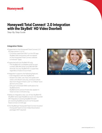
the seals until ready to install adapters or connect the piping.Install Bushings To ControlIf bushings are being installed on the control, mount them as follows:Bushings1. Remove the seal over the control inlet or outlet.2. Apply a moderate amount of good quality pipe compound to the bushing, leaving two end threads bare. On an LPinstallation, use compound that is resistant to LP gas. See Fig. 1.3. Insert the bushing in the control and carefully thread the pipe into the bushing until tight.Complete the instructions below for installing the piping, installing the control, and connecting the wiring. Makesure the leak test you perform on the control after completing the installation includes leak testing the bushings.LocationThe gas controls are mounted in the appliance vestibule on the gas manifold. If this is a replacement application, mountthe gas control in the same location as the old control.Locate the combination gas control where it cannot be affected by steam cleaning, high humidity, or dripping water,corrosive chemicals, dust or grease accumulation or excessive heat.To assure proper operation, follow these guidelines:Locate gas control in a well-ventilated area.Mount gas control high enough above cabinet bottom to avoid exposure to flooding or splashing water.Assure the ambient temperature does not exceed the ambient temperature ratings for each component.Cover gas control if appliance is cleaned with water, steam, or chemicals or to avoid dust and greaseaccumulation.Avoid locating gas control where exposure to corrosive chemical fumes or dripping water are likely.Install Piping to ControlAll piping must comply with local codes and ordinances or with the National Fuel Gas Code (ANSI Z223.1, NFPA No.54), whichever applies. Tubing installation must comply with approved standards and practices.1. Use new, properly reamed pipe that is free from chips. If tubing is used, make sure the ends are square, deburredand clean. All tubing bends must be smooth and without deformation.2. Run pipe or tubing to the control. If tubing is used, obtain a tube-to-pipe coupling to connect the tubing to thecontrol.3. Install a sediment trap in the supply line to the control. See Fig. 2.Install Control1. Can be mounted in any direction.2. Mount so the gas flow is in the direction of the arrow on the bottom of the control.NOTE: Gas valve will leak if installed backwards.3. Thread the pipe the amount shown in Table 5 for insertion into control or adapters. Do not thread pipe too far.Valve distortion or malfunction can result if the pipe is inserted too deeply.4. Apply a moderate amount of good quality pipe compound (do not use Teflon tape) only to the pipe, leaving twoend threads bare. On LP installations, use a compound resistant to LP gas. See Fig. 1.5. Remove the seals over the control inlet and out-let if necessary.6. Connect the pipe to the control inlet and outlet. Use a wrench on the hex end of the control. See Fig. 3.Table 5. NPT Pipe Thread LengthThread Maximum DepthPipe PipePipe can beSize thisinserted intoAmount Control3/8b9/16(14)1/23/4 (19) 1/2 (13)3/8 (9)
All dimensions are in inches (mm).OK when bushings are used.Fig. 1. Use moderate amount ofpipe compound.ALL BENDS IN METALLIC TUBING SHOULD BE SMOOTH.CAUTION: SHUT OFF THE MAIN GAS SUPPLY BEFORE REMOVING END CAP TO PREVENT GAS FROMFILLING THE WORK AREA. TEST FOR GAS LEAKAGE WHEN INSTALLATION IS COMPLETE. M3077
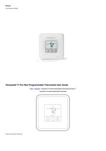
WiringFollow the wiring instructions furnished by the appliance manufacturer, if available, or use the general instructionsprovided below. When these instructions differ from the appliance manufacturer, follow the appliance manufacturerinstructions.IMPORTANT: All wiring must comply with applicable electrical codes and ordinances.WARNING: Electrical Shock Hazard or Equipment Damage Hazard.Can cause serious injury, death or equipment damage.Disconnect power supply before making wiring connections to prevent electrical shock or equipment damage.1. Check the power supply rating on the gas control and make sure it matches the available supply. Install atransformer and other controls as required.2. Connect the control circuit to the gas control terminals. See Fig. 4 and 5.3. Two stage gas valve wiring:MV – Main valve or low fire.C – Common terminal of ignition coils.HI – Second stage or high fire.4. For single stage controls (VR8215S,T):adjust thermostat heat anticipator to 0.50A rating stamped on valve label.For two stage controls (VR8215Q,N):adjust thermostat heat anticipator to 0.90A rating stamped on valve label.
POWER SUPPLY. PROVIDE DISCONNECT MEANS AND OVERLOAD PROTECTION AS REQUIRED.ALTERNATE LIMIT CONTROLLER LOCATION.MAXIMUM IGNITER-SENSOR CABLE LENGTH: 3 ft. (0.9 m) OR LESS.3A REPLACEABLE FUSE.ALARM TERMINAL PROVIDED ON SOME MODELS.
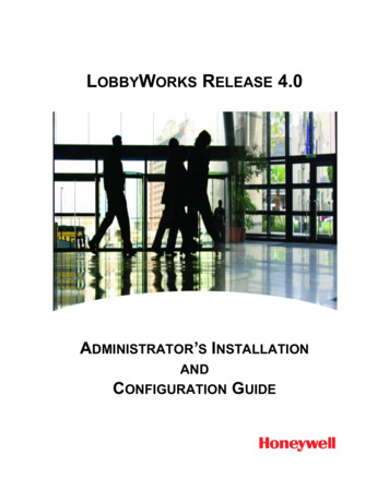
1. POWER SUPPLY. PROVIDE DISCONNECT MEANS AND OVERLOAD PROTECTION AS REQUIRED. MAKESURE L1 AND L2 ARE NOT REVERSED; THIS WOULD PREVENT FLAME DETECTION.2. ALTERNATE LIMIT CONTROLLER LOCATION.3. SEN TERMINAL AND Q354 FLAME SENSOR ON D MODELS ONLY.STARTUP AND CHECKOUTOn-Off SwitchThe on-off switch settings are as follows:OFF: Prevents main gas flow through the control.ON: Permits gas to flow into the control body. Under control of the thermostat and direct ignition module, gas canflow to the main burners.NOTE: Controls are shipped with the electronic on-off switch in the ON position.Perform Gas Leak TestFire or Explosion Hazard.Can cause property damage, severe injury or death.Perform Gas Leak Test every time work is done on a gas system.IMPORTANT: Do not spray soap and water solution on the gas control. This can damage the control. Do not use anexcessive amount of soap and water solution to perform the gas leak test. Apply only to pipe thread areas.Gas Leak Test1. Paint pipe connections upstream of the gas control with rich soap and water solution. Bubbles indicate a gas leak.2. If a leak is detected, tighten the pipe connections.3. Light the main burner. Stand clear of the main burner while lighting to prevent injury caused from hidden leaksthat could cause flashback in the appliance vestibule.4. With the main burner in operation, paint the pipe joints (including bushings) and the control inlet and outlet with
rich soap and water solution.5. If another leak is detected, turn the gas control to off, tighten the joints and pipe connections.6. Replace the part if a leak cannot be stopped.Check and Adjust Gas Input and Burner Ignition1. Do not exceed input rating stamped on appliance nameplate, or manufacturer’s recommended burner orificepressure for size orifice(s) used. Make certain primary air supply to main burner is properly adjusted for completecombustion. Follow appliance manufacturer instructions.2. IF CHECKING GAS INPUT BY CLOCKING GAS METER: Make certain there is no gas flow through the meterother than to the appliance being checked. Other appliances must remain off with the pilots extinguished (ordeduct their consumption from the meter reading). Convert flow rate to Btuh as described in form70- 2602, Gas Controls Handbook, and compare to Btuh input rating on appliance nameplate.3. IF CHECKING GAS INPUT WITH MANOMETER: Make sure the gas control is in the OFF position beforeremoving outlet pressure tap plug to connect manometer (pressure gauge). Also move the gas control switchback to the OFF position when removing the gauge and replacing the plug. Before removing inlet pressure tapplug, shut off gas supply at the manual valve in the gas piping to the appliance or, for LP, at the tank. Also shut offgas supply before disconnecting manometer and replacing plug. Repeat Gas Leak Test at plug with main burneroperating.NOTE: Check the inlet pressure before adjusting the pressure regulator.Standard (S, Q) and Slow-Opening (T, N) Models1. Carefully check the main burner lightoff. Make sure that the main burner lights smoothly and that all ports remainlit.2. Check the full rate manifold pressure listed on the appliance nameplate. Gas control full rate outlet pressureshould match this rating.3. With main burner operating, check the control flow rate using the meter clocking method or check pressure usinga manometer connected to the outlet pressure tap on the control. See Fig. 7.4. If necessary, adjust the pressure regulator to match the appliance rating.5. If the desired outlet pressure or flow rate cannot be achieved by adjusting the gas control, check the gas controlinlet pressure using a manometer at the inlet pressure tap of the gas control. If the inlet pressure is in the nominalrange (see Table 6), replace the gas control. Otherwise, take the necessary steps to provide proper gas pressureto the control.6. Two stage valves will require outlet pressure verification for both HI and LO fire.Check Safety LockoutSlow-Opening (T, N) Controls Only1. With the system power off and the thermostat set to call for heat, manually shut off the gas supply.2. Energize ignition control and start timing safety lockout time. When spark ignition terminates, stop timing.NOTE: When using the VR8215T or VR8215N, the specified ignition control safety lockout time must exceed 8.5seconds for the system to function properly.3. After spark cutoff, manually reopen the gas control switch. No gas should flow to the main burner.4. Reset the system by adjusting the thermostat below room temperature, wait 30 seconds, and then move thethermostat setting up to call for heat. Normal ignition should occur.5. Two stage valves will require outlet pressure verification for both HI and LO fire.Table 6. Pressure Regulator Specification Pressures in inches WC (kPa).
Model TypeType ofGasNominal Inlet Pressure Factory Set Nominal OutletRangePressureSetting Range5.0-7.03.52.5-3.51Single 0-14.010.08.0-12.0(3.0-3.5)(2.5)(2.0-3.0)1.5 – 2.5 Low(0.4-0.6) LowNAT5.0-7.01.7 (0.4) Low(1.2-1.7)3.5 (0.9) High2.5-3.7 High(0.6-0.9) HighTwo Stage Standard,SlowLP12.0-14.05.0 (1.3) Low(3.0-3.5)10.0 (2.5) High4.5 – 7.0 Low (1.1-1.7)Low 8.0-11.0 High(2.0-2.7) HighCheck Safety Shutdown PerformanceWARNING: Fire or Explosion Hazard.Can cause property damage, severe injury or death.Perform the safety shutdown test any time work is done on a gas system.NOTE: Read steps 1 through 7 before starting, and compare to the safety shutdown or safety lockout testsrecommended for the direct ignition (DI) module. Where different, use the procedure recommended for the ignitionmodule.1. Turn off gas supply.2. Set thermostat or controller above room temperature to call for heat.3. Watch for ignition spark or for glow at hot sur-face igniter either immediately or following pre-purge. See DirectIgnition module specifications.4. Time the length of spark operation. See the Direct Ignition module specifications.5. After the module locks out, open the manual gas cock and make sure no gas is flowing to the main burner.6. Set the thermostat below room temperature and wait one minute.7. Operate system through one complete cycle to make sure all controls operate properly.MAINTENANCEWARNING: Fire or Explosion Hazard.Can cause property damage, severe injury, or death.
Do not disassembly the gas control; it contains no replaceable components. Attempted disassembly, repair, or cleaningcan damage the control, resulting in gas leakage.Regular preventive maintenance is important in applications in the commercial cooking and agricultural and industrialindustries that place a heavy load on system controls because:In many such applications, particularly commercial cooking, the equipment operates 100,000 to 200,000 cyclesper year. Such heavy cycling can wear out the gas control in one to two years.Exposure to water, dirt, chemicals and heat can damage the gas control and shut down the control system.The maintenance program should include regular checkout of the control as outlined in the Startup and Checkoutsection, and the control system as described in the appliance manufacturer literature.Maintenance frequency must be determined individually for each application. Some considerations are:Cycling frequency. Appliances that may cycle 20,000 times annually should be checked monthly.Intermittent use. Appliances that are used seasonally should be checked before shutdown and again before thenext use.Consequence of unexpected shutdown. Where the cost of an unexpected shutdown would be high, the systemshould be checked more often.Dusty, wet, or corrosive environments. Since these environments can cause the gas control to deteriorate morerapidly, the system should be checked more often.The system should be replaced if:It does not perform properly on checkout or troubleshooting.The gas control is likely to have operated for more than 200,000 cycles.The control is wet or looks as if it has been wet.SERVICEWARNING: Fire or Explosion Hazard.Can cause property damage, severe injury or death.Do not disassemble the gas control; it contains no replaceable components. Attempted disassembly, repair, or cleaningcan damage the control, resulting in gas leakage.Equipment Damage Hazard.Can burn out thermostats or other components in the control string. Never apply a jumper across (or short) the valvecoil terminals, even temporarily.If Main Burner Does Not Come On With Call For Heat1.2.3.4.5.Confirm the gas control switch is in the ON position.Adjust thermostat several degrees above room temperature.Using ac voltmeter, measure across the quick connect terminals at gas control.If voltage is incorrect or not present, check control circuit for proper operation.If proper voltage is present, replace gas control.CONVERTING GAS CONTROL FROM NATURAL GAS TO LP GAS (OR LP GAS TO NATURAL GAS)WARNING: Fire Or Explosion Hazard.Can cause property damage, severe injury or death.1. Always change the main orifices when converting from natural to LP gas or from LP to natural gas. Carefullyfollow appliance manufacturer specifications and instructions to assure proper appliance conversion.2. Gas controls are factory-set for natural (and manufactured) or LP gas. Do not attempt to use a gas control set fornatural (manufactured) gas on LP gas, or a gas control set for LP gas on natural (manufactured) gas.Single StageSingle stage controls with standard and slow-opening regulators (model numbers with suffix S or T) can be convertedfrom one gas to the other with a conversion kit. See Table 4 for the correct conversion kit part number.
1.2.3.4.5.6.7.Turn off gas supply at the appliance service valve.Remove regulator cap screw and save. See Fig. 7.Remove the pressure regulator adjusting screw. See Fig. 6.Remove the existing spring.Insert the replacement spring. See Fig. 6.Install the new plastic pressure regulator adjustment screw.Check the regulator setting using a manometer or by clocking the gas meter. See “Check and Adjust Gas Inputand Burner Ignition” on page 5.8. Adjust regulator by following the Single Stage Regulator Adjustment process, below.9. Reinstall the regulator cap screw.10. Mount conversion label on the gas control.SINGLE STAGE REGULATOR ADJUSTMENTIf necessary, adjust the pressure regulator to match the appliance rating. See Table 6 for factory-set nominal outletpressure and adjustment range.
a. Remove the pressure regulator adjustment cap screw.b. Using a screwdriver, turn the inner adjustment screw (Fig. 6) clockwise to increase or counterclockwise todecrease the gas pressure to the burner.c. Always replace the cap screw and tighten firmly to prevent gas leakage.Two StageTo convert from one gas to another:1.2.3.4.5.6.7.8.9.10.11.Turn off gas supply at the appliance service valve.Remove/unsnap plastic regulator cap. See Fig. 8.Remove regulator assembly by rotating 7/16 Hex to left with supplied conversion tool. See Fig. 9.Remove spring from regulator assembly and replace with new spring.Reinstall regulator assembly back into valve housing, turning clockwise with 7/16 Hex conversion tool.Rotate regulator assembly 6 turns to reach a nominal high fire setting of approximately 3.5 inches WC.Check the regulator setting using a manometer or by clocking the gas meter. See “Check and Adjust Gas Inputand Burner Ignition” on page 5.Adjust high fire first by adjusting exterior 7/16 Hex, After high fire has been set, adjust low fire utilizing interior 3/32allen. See Fig. 8 and the Two Stage Regulator Adjustment process, below.Reinstall the plastic regulator cap.Mount conversion label on the gas control.Install the gas control and appliance according to the appliance manufacturer instructions.
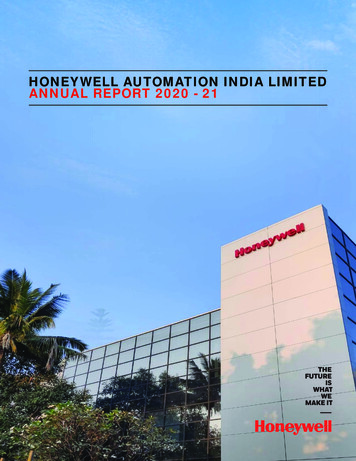
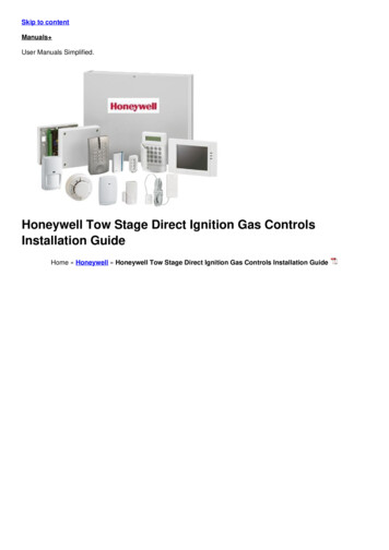
Fig. 8. Top view of VR8215 two stage control with regulator cover removed.TWO STAGE REGULATOR ADJUSTMENTNOTE: Check the inlet pressure before adjusting the pressure regulator.
Two-stage VR8215 requires that you check and adjust both high and low pressure regulator settings. Adjust high firebefore adjusting low fire. Two-stage appliance operating sequences vary. Consult the appliance manufacturerinstructions for the specific operating sequence and regulator adjustment procedure for the appliance in which thecontrol was installed.1.2.3.4.5.6.7.8.9.10.11.Consult the appliance manufacturer’s instructions to obtain the high and low fire regulator pressure settings.Install the regulator spring and regulator adjustment as per the conversion instructions above.Set the appliance to operate on high fire.With main burner operating on high fire, calibrate the high fire setting using the meter clock-ing method or using amanometer connected to the outlet pressure tap on the control.Adjust the high pressure regulator to match the appliance rating.See Table 6 for the adjustment range of the gas valve. The appliance requirements should be within thisrange.Using the conversion tool, turn the Hi adjustment 7/16 Hex clockwise to increase or counterclockwise todecrease the gas pressure to the burner.After high pressure has been calibrated, use the same measurement method to calibrate the low stage. Twostage appliance operating sequences vary. Consult the appliance manufacturer instructions for the specificoperating sequence and for instructions on how to prevent the control from moving to high stage while calibratingthe low pressure regulator setting.With the main burner operating on low fire, calibrate the low fire regulator setting using the same measurementmethod used to calibrate high stage. See Fig. 9.Adjust the low pressure regulator to match the appliance rating.See Table 6 for the adjustment range of the gas valve. The appliance requirements should be within thisrange.Using conversion tool, turn the Lo adjustment 3/32 allen screw clockwise to increase or counterclockwise todecrease the gas pressure to the burner. See Fig. 9.Once high and low pressure regulator settings have been calibrated and verified, reinstall the regulator cover.If the desired outlet pressure or flow rate cannot be achieved by adjusting the gas control, check the gas controlinlet pressure using a manometer at the inlet pressure tap of the gas control. See Fig. 8. If the inlet pressure is inthe nominal range (see Table 6), replace the gas control. Otherwise, take the necessary steps to provide propergas pressure to the control.Replace pressure tap plugs.Mount conversion label on the gas control.Leak test the gas valve. See “Perform Gas Leak Test” on page 5.INSTRUCTIONS TO THE HOMEOWNERWARNING: Fire or Explosion Hazard.Can cause property damage, severe injury, or death.Follow these warnings exactly:1. Before lighting, smell around the appliance for gas. Be sure to smell next to the floor because LP gas is heavierthan air. If you smell gas:a. Turn off the gas supply at the appliance service valve. On LP gas systems, turn off the gas supply at the gastank.b. Do not light any appliances in the house.c. Do not touch electrical switches or use the phone.d. Leave the building and use a neighbor’s phone to call your gas supplier.e. If you cannot reach your gas supplier, call the fire department.2. Replace the gas control in the event of any physical damage, tampering, bent terminals, missing or broken parts,stripped threads, or evidence of exposure to heat.IMPORTANT: Follow the operating instructions provided by the heating appliance manufacturer. The information belowdescribes a typical control application, but the specific controls used and the procedures outlined in your appliancemanufacturer instructions can differ, requiring special instructions.To Turn ON ApplianceSTOP! Read the Warnings Above Before Proceeding.1. The lighting sequence on this appliance is automatic; do not attempt to manually light the main burner.
2. If the furnace does not come on when the thermostat is set several degrees above room temperature, set thethermostat to its lowest setting to reset the safety control.3. Remove the burner access panel if provided on your appliance.4. Push the on-off switch to the OFF position.5. Wait five minutes to allow any gas in the combustion chamber to vent. Then if you smell gas, STOP! Follow Step1 in the Warning above. If you do not smell gas, continue with the next step.6. If you do not smell gas, push the electronic on-off switch to the ON position.7. Replace the burner access panel.8. Reset the thermostat to the desired temperature.9. If the appliance does not turn on, turn the gas control switch to OFF and contact a qualified service technician forassistance.Turning Off the ApplianceVacation ShutdownSet the thermostat to the desired room temperature while you are away.Complete Shutdown1.2.3.4.Turn off power to the appliance.Turn off the gas supply to the appliance.Push the on-off switch to the OFF position. Appliance will completely shut off.Follow the procedure in the Instructions to the Homeowner section above to resume normal operation.WEEE Directive:At the end of their useful life the packaging and product should be disposed of by a suitable recycling centre.Do not dispose of with normal household waste.Do not burn.Home and Building Technologies In the U.S.:Honeywell1985 Douglas Drive NorthGolden Valley, MN 55422-3992 custo
The VR8215S,T Single Stage and VR8215Q,N Two Stage Direct Ignition Gas Controls are used in gas-fired appliances with up to 150 ft3/hr capacity at 1 in. wc pressure drop on natural gas. They have been optimized for direct ignition applications and include a on/off switch and a pressure regulator. Valve capacities are shown in Table 1.