Transcription
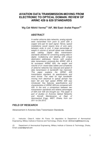
AVIATION DATA TRANSMISSION-MOVING FROMELECTRONIC TO OPTICAL DOMAIN: REVIEW OFARINC 429 & 629 STANDARDSWg Cdr Nikhil Verma(1) IAF, Md Easir Arafat Papon(2)ABSTRACTIn earlier airborne data networks, analog signalswere transmitted from point to point with acopper wire pair for each signal. Hence, typicalinstallations would require tens of wire pairsbetween ends to end. A large percentage ofweight & volume of aircraft space was towardsdata cabling. Digital data transmissionstandards allowed for converting analog data todigital, multiplexing and labeling with uniquedestination addresses. Hence, with aviationdata transmission protocols-like ARINC 429 &its successor ARINC 629, the weight andvolume of on- board data cables and complexityof airborne networks has reduced and speed ofdata transmission & bandwidth has improved.This paper explains the ARINC 429transmission standard, its specifications andword format. The need for high bandwidthmoving from electrical to optical domain hasbeen felt and high speed ARINC 629 wasintroduced. Key features, specifications andcharacteristics of ARINC 629 are compared with429. In the end, a comparison between twotransmission standards and relative advantagesof 629 over 429 are brought out. This paper ispart of studies on Avionics Optical Networksand Aircraft Maintenance at Dept ofAeronautical Engg., MIST, Dhaka, from Jun2011 to Oct 2012.FIELD OF RESEARCHAdvancement in Avionics Data Transmission Standards.(1)Instructor, Class-A, Indian Air Force, On deputation to Department of AeronauticalEngineering, Military Institute of Science and Technology, Dhaka. Email: nikhilverma@iitkalumni.org(2)Department of Aeronautical Engineering, Military Institute of Science & Technology, Dhaka,Email: a.easir@gmail.com1
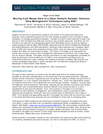
1.0INTRODUCTIONData transmission is conveyance of information from source to destination. In analogavionics data transmission system, at least one pair of wire is required for eachsignal between the sources & destination. Hence, a typical point to point analogairborne network would require 10s of pairs of wires. In digital data bus, analogsignals are converted into digital equivalents, assigned unique address labels,multiplexed and transmitted down a single pair of wire which makes up a data bus,which can either be serial or parallel. Integrated digital avionics data bus allows datamultiplexing, transmission/reception and communication of on-board avionics data inmodular avionics architecture. In vogue, data bus protocols are: ARINC 429, ARINC629, MIL-STD 1553, MIL-STD 1773, Commercial Serial Digital Bus (CSDB) andAvionics Serial Communication Bus (ASCB).2.0ARINC 429ARINC 429 or simply 429 is a Digital Information Transfer system (DITS) introducedin 1977 by Aeronautical Radio Incorporated (ARINC) [A]. It has been installed on mostcommercial transport aircraft including; Airbus A310, Boeing 727, 737, 747, 757, and767; and McDonnell Douglas MD-11[B]. It defines both the hardware and dataformats required for bus transmission. Hardware consists of a single transmitter orsource connected up to 20 receivers or sinks on single shielded twisted wire pair[C].Data can be transmitted in simplex mode; bi-directional transmission would require aparallel wire or a bus. The devices, line replaceable units (LRUs), are mostcommonly configured in a Star (Fig.1) or Bus-Drop (Fig.2) topology. This simplearchitecture, almost point-to-point wiring, provides highly reliable data transfer [D, TxTransmitting TixFigure.1: Star TopologyFigure.2: Bus-drop Topology2
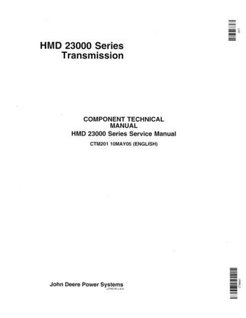
2.1 ARINC 429 CHARACTERISTICSARINC 429 is a self-clocking, asynchronizing data bus; hence messages can start atany moment of the time line. And if there are no messages, the transmission line isin null state and there is no voltage, which is a power saving advantage. A set of bitsor bytes comprising the smallest unit of addressable memory is called word. 429transmitters might supply more than one data word at a time and in such a case thereceiver has to be given the information about order of reading the words. 429 hastwo variants; a high speed variant operating at 100 kbps and low speed variant at 13kbps. There are three logic states in the 429 system: logic-0, logic-1 and null. Logic-1state is between 6.5 V and 13.0 V, while logic-0 state is the same except fornegative voltage and when no pulse is transmitted, the bus is in the null state. If anyof the two lines of the twisted pair shorts to ground, transmitter voltage is cut in halfwhich is an unacceptable range for the receiver [D, E, F].2.2 ARINC 429 WORD FORMAT AND DATA ENCODINGARINC 429 transmitters are always transmitting, either data words or NULL state [G].Most ARINC 429 messages contain only one data word consisting of Binary (BNR),Binary Coded Decimal (BCD) or alphanumeric data. 429 data words are 32 bit longmade up of five primary fields which are shown in Fig.3.MSB32 31 30PSSM29 ---------- 11MSBLSBData10 9SDILSB8--------1LabelFigure.3: ARINC 429 32 bit wordThe MSB is always the parity bit for ARINC 429 which is normally set to odd exceptfor certain tests. It means that there must be an odd number of “1” bits in the 32-bitword and that are insured by either setting or clearing the parity bit. Bits 31 and 30contain the Sign/Status Matrix (SSM) which contains hardware equipment condition,operational mode, or validity of data content. Bits 29 through 11 contain the data,which may be in a number of different formats while bits 10 and 9 provide aSource/Destination Identifier (SDI). This is used for multiple receivers to identify thereceiver for which the data is destined. Bits 8 through 1 contain a label identifying thedata type and the parameters associated with it [B]. ARINC 429's data encoding usesa Complementary Differential Bipolar Return-to-Zero (BPRZ) transmission waveform,Fig. 4 refers. Pulse rise and fall times are controlled by RC circuits built into ARINC429 transmitters [G]. This circuitry minimizes overshoot ringing common with shortrise times. Allowable rise and fall times and other parameters for both high & lowspeed ARINC 429 are shown in Table-1. It can be clearly seen that it’s not merelythe data speed that distinguishes between high & low speed 429 standards, but alsothe rise & fall time.The Bit rise & fall time for low speed 429 are approximately 9times slower than high speed 429. Approximately the same is the rate to bit ratebetween the two catagories of ARINC 429.3
1 bit time bit time Rx90%Tx10%RiseFallTimeFigure.4: ARINC 429 Waveform ParametersBit TimingHigh Speed 429Low Speed 429Bit Rate100 kbps 1%12 – 14.5 kbps 1%1 bit time10 µ sec 2.5%(1/Bit rate) µ sec 2.5%½ bit time5 µ sec 5%(1 bit time/2) 5%Rise Time1.5 µ sec 0.5 µ sec10 µ sec 5 µ secFall Time1.5 µ sec 0.5 µ sec10 µ sec 5 µ secTable.1: ARINC 429 waveform parametersEvery LRU transmitter has interface chips providing line drivers, receivers and logictranslation from three-level signals to logic zeros and ones. Most sophisticated chipsinclude registers and interface circuits for direct application to a microprocessor bus.Introduction of 429 reduced the bulk & volume of wires in the aircraft. Tuning ofvarious LRU required only keying or programming the parameters from one sourceto multiple receivers thus number of control panels is reduced.3.0ARINC 629The need for high-bandwidth airborne avionics data links that are lightweight,immune to electromagnetic interference and highly reliable are always felt. So, thenext stage of development is optical fiber data communication. Modern digitalavionics systems require a system capable of transporting microwave and millimeterwave RF signals that carry digital data on board an aircraft [H]. The high bandwidthto-weight ratio, performance and routing flexibility offered by the combination ofsingle mode optical fiber and wavelength division multiplexing (WDM) are among theprime attractions justifying the optical network approach to on-board avionicscommunications systems [I]. The ARINC 629 is a new standard for aviation industry4
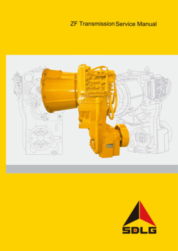
for the transformation of digital data between avionics system elements. It was firstintroduced in May 1995 and is currently used on the Boeing 777, Airbus A330 andA340 aircraft [J]. The ARINC 629 civil aircraft data bus standard has been developedas a successor to ARINC 429. It is used in the MAC layer protocol [O]. By the conceptof bus cycle, this protocol manages periodic and aperiodic traffic exchanges. Itsunique feature is that there is no need for a bus controller and bus access isdetermined by each terminal independently [D].3.1 ARINC 629- SPECIFICATIONS AND CHARACTERISTICSARINC 629 source transmits either broadcast or address specific message to all orspecific receiver or sinks. If the sinks equipment needs to reply, each will need to befitted with own transmitter and a specific physical bus for the same. The single pair ofwire connecting LRUs works in full duplex mode. In 629 LRU may transmit andreceive digital data using a standard protocol. The protocol is described as CarrierSense Multiple Access/ Collision Avoidance (CSMA/CA) [K, N]. 629 is a dualredundant data bus architecture where two buses are hot standby to each other in alinear bus topology, Fig. 5. Each terminal can transmit 629 data to and receive datafrom every other terminal on the data bus, which allows much more freedom in theexchanging of data between units in the avionics system. The 629 data bus cablehas an unshielded twisted pair of wires and can be up to 100 meters long. Remoteterminals are autonomous and for timing synchronization each RT has independenttransmitter and receiver PROM for sequencing the nal-4Terminal-5Multiple SourcesMultiple SinkFigure.5: ARINC 629 Dual Redundant Data BusTo identify the labels of messages, PROM is available in each RT. This feature is notavailable in 429, where all these activities are done by master controller (MC). 629have unique label word and each message has a source channel identification code(CID) which identifies the source of messages.5
3.2 WORD FORMATARINC 629 20 bit data word format is shown in Fig. 6, [A, J]. The first three bits arerelated to word time synchronization. The next 16 bits are the data contents, and thefinal bit is a parity bit. Data groups transmitted by ARINC 629 are called messages.Messages are comprised of word strings, up to 31 word strings can be in a message.So, maximum 620 bits are possible in a word string.Sync123Data (depending upon word type)Parity4 5 6 1920Figure.6: ARINC 629 Word FormatThe ARINC 629 standard defines a multi-level protocol for inter LRUcommunications across a common, multiple access data bus [L]. In 429 stubs areconnected with the data bus wherease in 629 there is no stub and even there is nomaster controller in 629. All the functions MC does in 429 are done by RTs. TheseRTs have both transmiter and receiver [D]. ARINC 629 can be implemented in threemedia: wire, inductive or voltage coupling and optical fiber [P]. Optical implementationoffers the same alternative bus configuration as of DOD-STD-1773 which is theoptical equivalent of MIL-STD 1553 having the same word structure and length andbus protocol. The optical power levels, wavelengths and means of distributing opticalpower in any specific implementation must be contained in a specification whichrefers this standard. This feature ensures that the best available technology is usedwhen the system is built [M].4.0KEY DIFFERENCES BETWEEN ARINC 426 AND ARINC 629FeaturesARINC 429ARINC 629Year of introduction19771995Bus ArchitecturePortsWiresTransmission mode &couplingSimplex point to point2Time division multiplex1ststandard, 2nd optionalShielded twisted pair of Unshielded twisted pair ofwireswiresVoltage direct connectionCurrent coupling6
EncodingBipolar, return to zeroData Rate12.5 & 100 kbps2 MbpsBus frequency12.0 kHz, 12.5 kHz, 14.5kHz, or 100 kHz2 MHzWords SelectableWord UpdateDivination of areasMaximum terdoubletsper 620 words per wordstring, 32 word strings1 ms to 10 sec, (selectable) 1 ms to 10 sec, updaterate displayedinstantaneous, min ormax valueThree areas : logic 0, logic Four areas: Periodic1 and Nulltraffic, Urgent aperiodictraffic ,Non Urgentaperiodic traffic (backlog,new)20128Bit wise ComparisonData BitBits (11-29) carrying dataBits (4-19) carrying dataBits 1 to 8Bits(1-8) for labelFirst three bits are relatedtowordtimesynchronization.Parity BitBit no. 32 is parity bitBit no. 20 is parity bitTable.2: Comparison between ARINC 429 & ARINC 6295.0 CONCLUSIONAviation parameters like air speed, atmospheric pressure, altitude, engine RPM,navigation status, control surface position etc are measured in analog domain andtransmitted to on-board processors, displays and controls in electrical domain(ARINC 429 & 629). Over the years complexity of avionics systems has increasedand so is the requirement of high data bandwidth and speed of on-board avionicsnetwork. As a result developments are on for commercially adopting opticalstandards for avionics networks. Hence, ARINC 629 is being rapidly adopted for7
optical networks in aircraft. This paper gives a comparative overview of the twocommunication protocols used in avionics data bus. From an assessment of theirkey features it can be concluded that ARINC 429 is an easy-to-implement,inexpensive protocol whose reliability has been adequate for most applications in theearly ages. But, for high data rates, ARINC 629 has been advantageous, also incase of redundancy as well and hence, gradually optical fiber based airborneavionics are emerging for commercial aviation applications.6.0 REFERENCESA.Albert Helfrick, Principle of Avionics, ISBN 978-1-885544-27-8 pageno.316,317,318,319,332B.ARINC Protocol Tutorial (1500-029) , 16 July, 2004 ; Condor
ARINC 429 is a self-clocking, asynchronizing data bus; hence messages can start at any moment of the time line. And if there are no messages, the transmission line is in null state and there is no voltage, which is a power saving advantage. A set of bits or bytes comprising the smallest unit of addressable memory is called word. 429 transmitters might supply more than one data word at a time .