Transcription
Arivazhagan S., et al.; International Journal of Advance Research, Ideas and Innovations in TechnologyISSN: 2454-132XImpact factor: 4.295(Volume 5, Issue 4)Available online at: www.ijariit.comGSM and Arduino based power theft detection and protectionS. Arivazhaganarivazhagansalem123@gmail.comWolaita Sodo University, EthiopiaTsegaye Alemayehu Atisotsegayealemayehusj@gmail.comWolaita Sodo University, EthiopiaMohammed Awol Seidmashahabesha@gmail.comWolaita Sodo University, EthiopiaABSTRACTTheft of electricity is the criminal practice of stealing electrical power. It is a crime and is punishable by fines and/orincarceration. It belongs to the non-technical losses. According to the annual Emerging Markets Smart Grid: Outlook 2015study by the Northeast Group, LLC, and the world loses US 89.3 billion annually to electricity theft. The highest losses were inIndia ( 16.2 billion), followed by Brazil ( 10.5 billion) and Russia ( 5.1 billion). Electrical power theft detection and controlsystem is used to detect the consumer when they try to use the power illegally. Electricity theft happens when the customer usesenergy meter tampering such as placing a magnet near to energy meter, disconnecting the neutral line and shorting the phasecoil of the current transformer. To identify and control power theft here an intelligent system is introduced. It consists of twocurrent transformers that are used to measure the actual load current and the other is to measure the turning back or neutralcurrent. Those two current signals are fed to the microcontroller. The microcontroller will compare these two current signals.Depending on the comparison made by the microcontroller it concludes whether power is theft through bypassing the energymeter or not and a message will be sent to notify the authorized power vendor using GSM Hence the power vendor can easilyidentify the customer who is illegally consuming the power for that energy meter. Moreover, when there is an occurrence oftheft the relay will disconnect the load from the supply. The GSM based power theft control system is developed. We usedProteus software to analyze and estimate what the hardware will look like. Mainly this system consists of a microcontroller,energy meter, current transformers, LDR, relay, LCD, and GSM module.Keywords— Current transformer, Arduino Uno Micro Controller, LCD display, Relay, Energy meter1. INTRODUCTIONElectricity is one of the greatest technological innovations of mankind. It has now become a part of our life and one cannot thinkof a world without electricity. Electricity is now an important part of homes and industries. Almost all the devices at home andindustries running because of electricity. Electricity is needed to be protected for efficient power delivery to the consumer.Generation, transmission, and distribution of electrical energy involve many operational losses. There are two types of lossestechnical and non-technical losses overall technical losses occur naturally and are caused because of power dissipation intransmission lines, transformers, and other power system components. Technical losses in transmission and distributionscomputed with the information about total load and the total energy billed. While nontechnical losses cannot be preciselycomputed, but it can be estimated from the difference between the total energy supplied to the customers and the total energybilled. Moreover, non-technical losses are illegal utilization of power by electricity consumers. Electricity theft has emerged as aserious problem in power sectors especially in the developing countries. A huge amount of revenue is lost due to electricity theft.In some countries, this is so severe that governments are incurring losses instead of revenue. In some cases, government has toprovide subsidies to the power sector to maintain a reasonable price of electricity. The financial loss results in shortage of fundsfor investments to expand the existing power capacity and as a result government is failing to satisfy the ever-increasing demandfor electricity.A design of electricity theft monitoring system saves time as well as help to maximize profit margin for utility company workingin an electrical distribution network. The utility company can keep a constant eye on its costumer. This project provides anoverview of a GSM based efficient and effective Power Management. Now a day the problem of electricity theft has increased inrural areas and in industrial parks. Also, these thefts are quite noticeable in urban houses too. As a solution to this problem, anelectronic system that can control this is of great requirement. This project adds a new security measure to such type of electricitytheft control. The design is compact enough to setup this system in houses and industries. The main objectives of the projects areas follows:(a) To design a power supply circuit for current and voltage measurement/sensing circuit(b) To design and implement GSM based power theft control system to notify the power theft for electricity utility power supplier 2019, www.IJARIIT.com All Rights ReservedPage 581
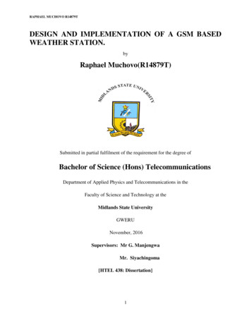
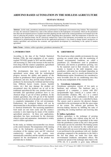
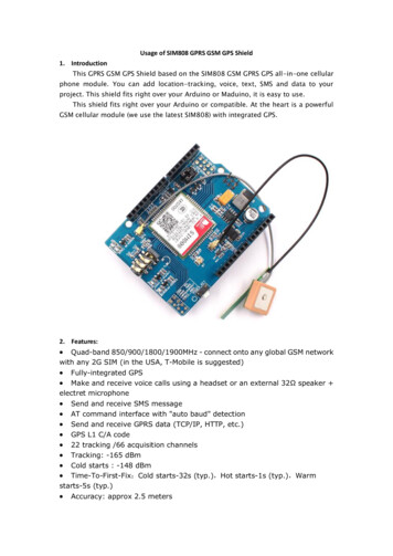
Arivazhagan S., et al.; International Journal of Advance Research, Ideas and Innovations in Technologyvia SMS message.(c) To check, verify and simulate the system in proteus software(d) To reduce man power required(e) To reduce unforeseen expenditure due to power theft.(f) To save wastage of time2. EXISTING SYSTEMOne of the major challenges in energy mater in recent time is the detection and elimination of electricity theft. However, theprevious theft control system is manual. That is moving from house to house in monitoring the power. Other than the loss ofrevenue to the utility provider, power theft also has adverse effects on consumers and society. it is difficult to obtain data whichidentifies specific locations where power theft is occurring. A Revenue Assurance and Audit Process are composed of macrofunctions to detect and analyze revenues involved in illegal consumption of electricity. Periodic inspection of illegal connectionsinvolves a lot of labor and strain for vigilant officials.3. IMPLEMENTED SYSTEM AND RESULTIn this project, GSM module is used to transmit the information about power theft to utility company. The main aim of this workis to use the GSM network alongside reducing theft and losses. This also can be used to disconnect the power supply to the housein case of electricity theft. In case of tampering, it can immediately send signal to the central server of the utilities. Anotheradvantage of the GSM is that it enables the utility engineers efficiently plan for network expansion while delivering power to thecustomer.Fig. 1: System block diagramFig. 2: Arduino Uno microcontrollersTable 1: Arduino Uno parametersMicrocontrollerArduino UnoOperating voltage5VInput voltage(recommended)7-12VInput voltage(limits)6-20VDigital I/O pins14(of which 6 provide PWM output)Analog input pins6DC current per input output pin40MaDC current for 3.3v pin50MaFlash memory32 kbSRAM2kb 2019, www.IJARIIT.com All Rights ReservedPage 582
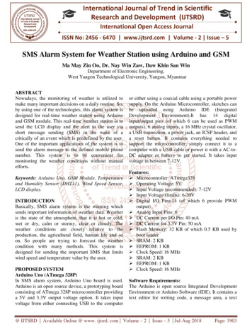
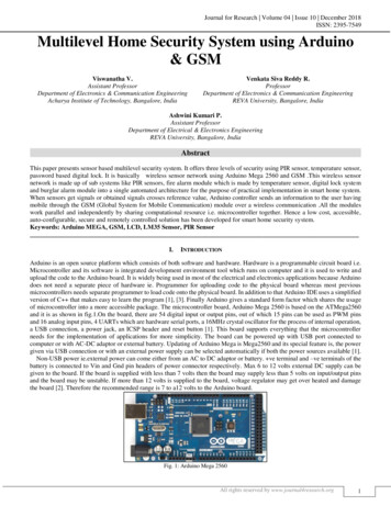
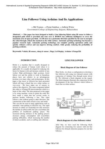
Arivazhagan S., et al.; International Journal of Advance Research, Ideas and Innovations in TechnologyEEPROM1kbClock speed16MHzLength68.6 mmWidth53.4 mmWeight25g3.1 Methods of Stealing Electric Power3.1.1 Shorting the phase current coil: When a consumer shorts the current coil of the meter the total current flows through theshorted path, so the meter cannot detect the current flow through it. Electrical power is given by the equation𝑃 𝑉𝐼 where; P:stands for power absorbed or delivered, I: for current through the device, V: for voltage across the device. So, if the current coil ofthe meter is shorted here I 0 ultimately leading to P 0.Fig. 3: Shortening the phase line (bypassing)3.1.2 Disconnecting the neutral line: A more common method of tampering analog meter is disconnecting the neutral line. Inthis condition, the meter cannot detect any voltage difference across the supply line and neutral line. As V 0 here, power will bezero by according to P VI formula. So, no energy consumption will be shown by the meter.Fig. 4: Disconnection the neutral line3.1.3 Tampering using magnet: We know that Aluminum disk is revolving by the magnetic flux produced inside the device dueto current flow. If a magnet is kept in the path of this flux, the magnet interferes with the flow of flux. So, the produced fluxcannot help the aluminum disk rotate. In this case, the disk is stopped or Revolves slower producing a smaller number ofrevolutions than that it should give. Therefore, accurate energy consumption is not shown in the meter.Fig. 5: Tampering using magnet 2019, www.IJARIIT.com All Rights ReservedPage 583
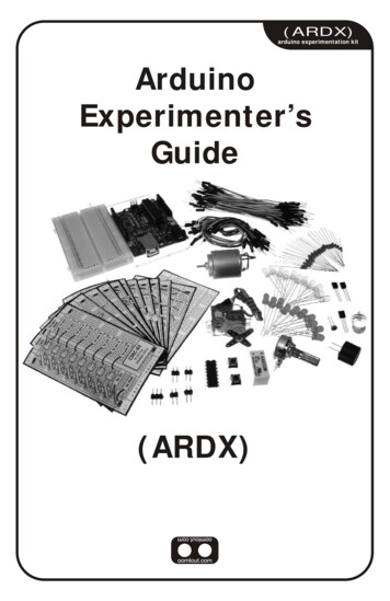
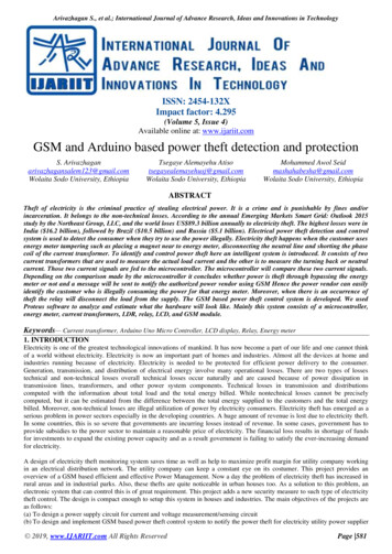
Arivazhagan S., et al.; International Journal of Advance Research, Ideas and Innovations in Technology3.2 Protection against shorting phase current coil3.2.1 CT1 and CT3: They are used in series within phase side and CT2 in the neutral side. If phase coil is shorted the currentflow through the shorted path so the CT1 current is zero but CT3 andCT2 current is not zero. The outputs of the three currenttransformers enter to the microcontroller. Our device works with the value of the difference between the readings of two CTs. Ifthe difference occurs between the two transformers microcontroller will notify to power supplier via GSM and SMS message willsend to Power Company.3.2.2 Protection against disconnecting the neutral line: When the neutral line of the meter is opened with the intention totamper, no current flows through the neutral line, there is no current flow in CT2. But current flows through CT1. The differencebetween these two current is fed to bridge rectifier and a regulated voltage will enter to the microcontroller. If the differenceoccurs between the two transformers microcontroller will notify to power supplier via GSM. SMS message will send to PowerCompany by GSM modem.3.2.3 Protection against magnetically tampering: The aluminum disc of the meter is divided into four sectors each occupyingsame amount of surface area. Two sectors are painted in black and rests are kept as they were before. Among these four sectors,two opposite sectors are of same color and the other two are without any color in the proposed device an additional LED and LDRare used to prevent magnetic tampering.The LED emits the light which falls upon the disc and the reflected light. is received by LDR. Now LDR will convert the receivedlight into electrical voltage and transfers it to the microcontroller. The micro controller receives the voltage value thereafter. Atnormal condition, the disc keeps rotating and the LDR output voltage is always changing. If someone attempts to tamper the meterby placing a magnet the received voltage of microcontroller will not change. The disc will not rotate in this case and thereforethere will be no change in the voltage from LDR to the microcontroller. When microcontroller doesn’t receive any change involtage from the LDR, then SMS message will send to Power Company by the help of GSM modem and indicate the occurrenceof power theft.4. SYSTEM FLOW CHARTFig. 6: System flow chartThe flow chart shows how the power theft is detected and protected. In the beginning, the power is supplied to the electric meter.The current in the phase line is measured by current sensor and also the current in neutral line is measured by current sensor at thesame time initialize the LDR sensor. Now the ARDUINO will compare the values read from the two current sensors if the valuesare the same the LCD will display “no power theft detection”. If not, GSM module will send a text message for power supplierthat power is being theft at that moment the contactor relay will trip and disconnect power from load. And the LDR sensor willcheck whether light intensity is varied or not if it varied send text message if it is not varied LCD display no power theft detection. 2019, www.IJARIIT.com All Rights ReservedPage 584
Arivazhagan S., et al.; International Journal of Advance Research, Ideas and Innovations in TechnologyFig. 7: Simulation Result with no power theft inFig. 8: Simulation Result LED and LoadThe above figure 8 shows After ARDUINO UNO R3 will read the two analog signals (current in phase line and current in neutralline) and compares. The microcontroller identifies the two values of the current transformer. If the two values are the same, forexample CT1 CT2 4 then there is no electricity theft occurrence is detected. It shows that the power consumed by the consumercorrect. Hence LED light indicator is off.Fig. 9: Simulation result with power theft in a virtual terminalFig. 10: Simulation Result with power theft in LCD 2019, www.IJARIIT.com All Rights ReservedPage 585
Arivazhagan S., et al.; International Journal of Advance Research, Ideas and Innovations in TechnologyFig. 11: Simulation Result of power theft loadSince the reading current transformers are not equal for example(CT1 4, CT2 2), the electricity theft happens, as a result, theARDUINO UNO R3 will inform by sending short message to power supplier electricity theft is happened using GSM modemconsequently ARDUINO UNO R3 will disconnect the load by turning ON the relay. Red LED will glow. It indicates thatelectricity theft happens. This is how electric power theft is detected and controlled.C program used for Arduino Uno#include LiquidCrystal.h #include SoftwareSerial.h SoftwareSerial mySerial(9,10);// initialize the library with the numbers of the interface pinsLiquidCrystal lcd(12, 11, 5, 4, 3, 2);int voltagePin A0;int ldrPin A2;int currentPin A1;int const relaypin 6;int const ledpin 7;float CT1,CT2;void 1,INPUT);lcd.begin(16,2);}void loop(){ int ldrpin A2;ldrpin analogRead(A2);CT1 analogRead(A0);CT1 lcd.print("CT1:");lcd.print(CT1);CT2 analogRead(A1);CT2 lcd.print("CT2:");lcd.print(CT2);if(ldrpin 15,CT1 CT2,CT1 CT2){lcd.setCursor(2,1);lcd.print(" power e(7,HIGH); 2019, www.IJARIIT.com All Rights ReservedPage 586
Arivazhagan S., et al.; International Journal of Advance Research, Ideas and Innovations in Technologydelay(100);mySerial.println(" HELO MANAGER OF EELPA");delay(2000);mySerial.println("POWER THEFT IS HAPPENNED!!");delay(2000);delay(2000);}else if(ldrpin 15&&CT1 CT2){lcd.setCursor(2,1);lcd.print(" power theft");mySerial.println("POWER THEFT IS HAPPENNED!!");mySerial.println("line taping italWrite(7,LOW);delay(100);}if(CT1 CT2&&ldrpin 15){lcd.setCursor(2,1);lcd.print("no power theft");mySerial.println("No POWER THEFT IS ay(100);digitalWrite(7,LOW);delay(100);}else if(CT1 CT2&&ldrpin 15){lcd.setCursor(2,1);lcd.print("power e(7,HIGH);delay(100);mySerial.println("HELO MANAGER OF EEPCO");delay(1000);mySerial.println("POWER THEFT IS HAPPENNED!!");delay(1000);mySerial.println(" Kebele 01");delay(1000);mySerial.println(" House no 1436");delay(1000);mySerial.println(" Counter ID 2627");delay(1000);mySerial.println(" magnet near to meter");delay(1000);}else if(CT1 CT2&&ldrpin 15){lcd.setCursor(2,1);lcd.print("power e(7,HIGH);delay(100);mySerial.println("HELO MANAGER OF EEPCO");delay(1000);mySerial.println("POWER THEFT IS HAPPENNED!!");delay(1000);mySerial.println(" Kebele 01");delay(1000);mySerial.println(" House no 1436");delay(1000);mySerial.println(" Counter ID 2627");delay(1000); 2019, www.IJARIIT.com All Rights ReservedPage 587
Arivazhagan S., et al.; International Journal of Advance Research, Ideas and Innovations in Technologydelay(1000);}else if (CT1 CT2){lcd.setCursor(2,1);lcd.print("power e(7,HIGH);delay(100);mySerial.println("HELO MANAGER OF EEPCO");delay(1000);mySerial.println("POWER THEFT IS HAPPENNED!!");delay(1000);mySerial.println(" Kebele 01");delay(1000);mySerial.println(" House no 1436");delay(1000);mySerial.println(" Counter ID 2627");delay(1000);mySerial.println(" Neutral Line cut");delay(1000);}}6. CONCLUSIONThe design, simulation and construction of a GSM-based power theft have been achieved. It has covered various forms ofelectricity theft which include unaccountability of servicemen, irregularities of billing leading to a reduction of funds by the utilitycompanies has also been achieved as this work prevents one on one contact between the end user and the workers. With remotemonitoring of the meter reading and sending SMS, whenever there are abnormal readings, in the customer electricity meter, thedeveloped system may able to help Utilities to reduce the incidences of household electricity theft. An automatic circuit breakercan be integrated into the unit so as to remotely cut off the power supply to the house or consumer who tries to indulge in powertheft. This system design mainly concentrates on single phase electrical distribution system. Automation of the customer billingsystem has been achieved as the meter keeps track of the consumer's load on a timely basis. This design, therefore, removes themanual reading of meters with its attached consequences of time-consuming system and bill manipulation which affects thecompany while adding higher bills to the consumer. The work also revolves around the automatic disconnection and connectionwhen the recharge is low or high respectively and extra cost due to reconnection can also be removed7. REFERENCES[1] H. T. M. R. a. H. B. W.A. Doorduin, Feasibility study of Electricity Theft detection using Mobile Remote Check Meters, 2004.[2] K. S. K. T. M. I. S. K. A. J. Nagi, "Detection of Abnormalities and Electricity Theft using Genetic Support Vector Machines,"IEEE Xplore, 2009.[3] M. V. R. Aryadevi Remanidevi Devidas, "Wireless Smart Grid Design for Monitoring and Optimizing Electric Transmissionin India," in Fourth International Conference on Sensor Technologies and Applications, 2009.[4] X. X. C. W. Lijuan Chen, "Research on Antielectricity Stealing Method Base on State Estimation," IEEE, 2011.[5] N. J. C. A. Solomon, "A Methodology for the Design of an Electricity Theft Monitoring System," Journal of Theoretical andApplied Information Technology, 2011. 2019, www.IJARIIT.com All Rights ReservedPage 588
(e) To reduce unforeseen expenditure due to power theft. (f) To save wastage of time 2. EXISTING SYSTEM One of the major challenges in energy mater in recent time is the detection and elimination of electricity theft. However, the previous theft control system is manual. That is moving from house to house in monitoring the power. Other than the .