Transcription
TA0136USER MANUALARDUINO 2 WHEELDRIVE ULTRASONICROBOT KIT
Contents1.Overview – TA0136 . 32.Getting started: Programming the arm robot using Arduino UNO . 33.4.5.2.1.What is Arduino? . 32.2.What is IDUINO UNO? . 32.3.What are the differences between other Arduino development boards we are providing? . 3Software installation . 43.1.Arduino Software/IDE . 43.2.Play with your first “Hello World” LED example . 53.3.Run your Arduino 2 Wheel Drive code . 7Hardware installation . 84.1.Unboxing and Component list . 84.2.Chassis Frame Installation . 104.3.Arduino Installation . 184.4.Sensor installation . 254.5.Switch . 324.6.Wire Connection . 34Have fun . 37Appendix . 38
1. Overview – TA0136In this instruction, we will introduce you through the fun project of the Arduino 2 Wheel DriveUltrasonic Robot Kit. Get your Arduino board kit. Let’s get started!2. Getting started: Programming the arm robot using Arduino UNO2.1. What is Arduino?Arduino is an open-source electronics platform based on easy-to-use hardware and software. Arduinoboards can read inputs - light on a sensor, a finger on a button, or a Twitter message - and turn it intoan output - activating a motor, turning on an LED, publishing something online. You can tell yourboard what to do by sending a set of instructions to the microcontroller on the board. To do so you usethe Arduino programming language (based on Wiring), and the Arduino Software (IDE), based onProcessing.2.2. What is IDUINO UNO?The Iduino Uno is on the ATmega328. It has 14 digital input/output pins (of which 6 can be used asPWM outputs), 6 analogue inputs, a 16 MHz ceramic resonator, a USB connection, a power jack, anICSP header, and a reset button.It contains everything needed to support the microcontroller; simply connect it to a computer with aUSB cable or power it with a AC-to-DC adapter or battery to get started. You can tinker with yourUNO without worrying too much about doing something wrong, worst case scenario you can replacethe chip for a few dollars and start over again.For more information: https://store.arduino.cc/usa/arduino-uno-rev32.3. What are the differences between other Arduino development boards we areproviding?There are a bunch of Arduino boards, they come in different shapes and sizes, with differentprocessing power, digital IO, and other capabilities. Rather than telling you guys what to buy, wehave put together a handy guide to show you the capabilities of each board.
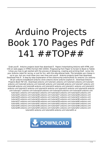
Table 1Comparison onardo2U4ATmega168NanoATmega328PMega 2560Operating/InputCPU Speed Analog In/Out Digital IO/PWM EEPROM [kB] SRAM [kB] Flash [kB]VoltageUSBUART5 V / 7-12 V16 MHz16/054/1548256Regular45 V / 7-12 V16 MHz6/014-Jun1232Regular15 V / 7-12 V16 MHz12/020-Jul12.532Micro10.5121165 V / 7-9 V16 MHz8/014-JunMini11232No need to worry anything for now as you will gain deep understanding after completing this funproject. Stay with me and get your hands dirty using Arduino UNO.For more information: https://www.arduino.cc/en/Products/Compare3. Software installationIn this section, we will introduce you the development platform where you translate creative mindinto codes and let it fly.3.1. Arduino Software/IDEDownload from here. Open Windows-based app by double clicking it and follow the instruction tocomplete(Remember to install everything driver for Arduino). Easy!Figure 1 Installation of driversConnecting your UNO board with your computerConnecting UNO and your PC by a blue USB cable, and if connected correctly you will see the greenpower LED light up and another orange LED is blinking.
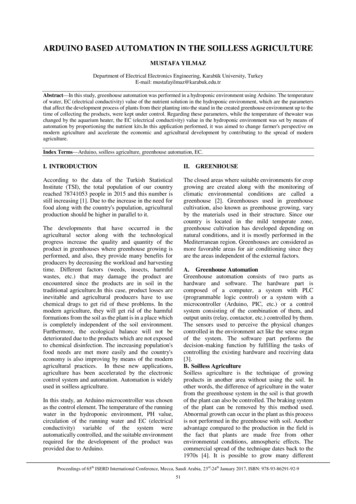
Find your Serial COMnumber and note it down.Figure 2 Check Your special COM and note it down the numberWe need to figure out which channel COM is currently communicating between PC and UNO.Following the path: Control panel Hardware and Sound Devices and Printers Device Manager Ports (COM & LPT) Arduino UNO (COMx)Note down the COM number as we require this later. In this case, we are using the COM 43.2. Play with your first “Hello World” LED exampleFirstly, let’s tell IDE where to find our Arduino port and which board you are currently using: Thefollowing instruction (Figure 3 and 4) shows the details:Configuration of Ports
Configuration of the Board
It’s time to play with you first simple example. Following the path by File Examples 01. Basics Blink. A new code window would pop up, press the arrow symbol to upload. You will notice theorange LED is blinking almost every second.3.3. Run your Arduino 2 Wheel Drive codeUpload to UNO
Done uploading!4. Hardware installation4.1. Unboxing and Component list-Acrylic ChassisDC MotorsSG90 Servo andBracketRubber WheelsMetal Pivot wheel
-Ultrasonic SensorArduino UNOSensor shield6 x AA Battery BoxL298N BoardSwitch-Fastener packageScrew, nuts andspacer components
4.2. Chassis Frame InstallationRemove the protective coverand prepare the items:- 4 x M3 * 6 Screw- 4 x M3 x 10 Spacer- Metal Pivot WheelAssemble the M3*10spacers and M3*6 screwsonto the Metal Pivot Wheel
Prepare the four M3*6screwsScrew in the metal pivotwheel to the chassis
Gather four M3*10 screwsand nuts to secure L289NboardScrew the L289N boardfrom the bottom chassis
Gather four M3*8 screwsand four M3*36 spacersSecure Spacers onto thechassis as per the picture onthe left.
Spacers/Stand-offs shouldlook like this
Gather the followingcomponents:- 2 x DC motors- 2 x Acrylic MotorBrackets- 4 x M3*30 screwsand nuts*Attaching wheel encodersare optional. These are notrequired for this particularproject
Place acrylic DC motorBrackets on both side ofthe motors as shown on theleftGather another two acrylicfasteners and two wheelsand nuts
Insert the acrylic fastenersfirst in pre-cut slotThen tighten and secure theDC motor with one nut onthe other side
Fix the other motor as wellPull the wire through as weneed to connect them to theL289N board4.3. Arduino InstallationLet’s fix the Arduino UNO and Sensor shield in the following steps.
Prepare thejumper cablesSeparate the jumpercable set into four andeight configurations
Connect the 8 jumperswith L289N board asshown.Prepare the following:- Battery pack- UNO board- Top acrylic chassis6 x nuts- 6 x M3*10 screws
Peel the protectivecoverPlace the battery packand UNO board on thetop acrylic chassis
Secure the screwsfrom the bottomIt should looklike this
Feed the jumper wirefrom the L289N boardand pull through to thetop acrylic chassis holeto connect with theUNO board laterMount the top acrylicchassis to the bottomchassis
Use four M3*6 screwsto secure top acrylicchassis.It should looklike this
Place the sensor shieldon the top of the UNOboard and ensure thepins line up with theUno Board.4.4. Sensor installationUltrasonic sensor acts as the eye of this 2-wheel drive car. In the following steps, we are going toguide you through the installation of ultrasonic sensor and servo.Items required inthis step
Assemble the FPVholder and servoUse two selftapping screws (inthe FPV package)to tighten
Prepare the itemsTo fit the servo horn intothe black holder we needto modify as pictured.Best tool to do this withis a side cutter
Place the modified servohorn inside the bracketand secure with 6 * M2.5screwsIt should look like this
To tighten the ultrasonicsensor, we can use severalcable ties (Not included inthe Kit). Alternatively, youcan use other methods:- Use rubber bands- Hot Melt Glue Gun- Thread or Plastic StringsIt should look like this
Prepare the Selftapping screw in theServo package andtighten the sensor partwith servo rackIt should look like this
Gather four M2.5 screwsand corresponding nutsin the FPV package tosecure to the bottomchassisFinished!4.5. SwitchThe switch can save you a lot energy turning the car on and off. However, it’s just an option. It can bedone by putting the switch in line with the battery box power wire.
Insert the switch in precut slotSolder the switch inline with the powercableThe following diagram shows the switch connection with battery pack and L289N.
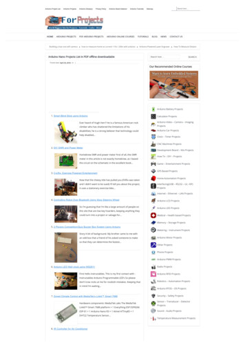
GND1b10VMSL289N11aBattery Pack4.6. Wire ConnectionYou are almost there. Final step is to wire the cables to power supply (i.e. Battery Box), UNO board,ultrasonic sensor and Servo. The following diagram shows the connection map. Don’t panic if this isyour first project, you can also follow the connection table 2.
Figure 3 Connection mapFigure 4 Arduino Sensor shield v5.0 Diagram
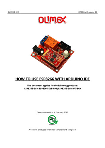
Table 2 Connection tableUNO board SensorShieldV691011VGV5VGVA1A0SL289NGNDVMS (Left)-(Left) (Right)-(Right)ENAIN1IN2IN3IN4ENBGND5V BatteryBoxGNDVMSMotorleftMotorRightServo Ultrasonicsensor (red)-(black) (red)-(black)S TrigEcho-
Figure 5 Overview5. Have funNow it’s time to have fun! Turn the power on, and see how your DIY Arduino Robot car goes! Afterfinal assembly and activation, the Robot car may require adjustments and debugging. The Robot willperform on how it is programmed. Figuring out what the code is doing is part of the learning process.Reopen your Arduino IDE and we assure you will learn a lot once you gain a deep understanding ofthe code.This kit is just a starting point and can be expanded to incorporate other sensors and modules. You arelimited by your imagination.We are also offering other Arduino Robot Kit versions where you can learn WIFI, Bluetooth, infraredremote control and so many more. Arduino 4 Wheel Drive with Ultrasonic & Line Tracer Bluetooth Robot KitArduino 4 Wheel Drive with Ultrasonic & Line Tracer Robot KitArduino 2 Wheel Drive Wireless Bluetooth Robot KitArduino Robot Arm 4dof Mechanical Claw KitCheck our website at Here.
AppendixCode:********Code begin********#include Servo.h int pinLB 6; // define pin6 as left back connect with IN1int pinLF 9; // define pin9 as left forward connect with IN2int pinRB 10; // define pin10 as right back connect with IN3int pinRF 11; // define pin11 as right back connect with IN4int inputPin A0; // define ultrasonic receive pin (Echo)int outputPin A1; // define ultrasonic send pin(Trig)int Fspeedd 0; // forward distanceint Rspeedd 0; // right distanceint Lspeedd 0; // left distanceint directionn 0; //Servo myservo; // new myservoint delay time 250; // set stable timeint Fgo 8;int Rgo 6;int Lgo 4;int Bgo 2;// forward// turn right// turn left// backvoid (pinRF,OUTPUT);pinMode(inputPin, INPUT);pinMode(outputPin, OUTPUT);myservo.attach(5); // define the servo pin(PWM)}void advance(int a) // HIGH);delay(a * 40);}void turnR(int d) //turn OW);delay(d * 50);}void turnL(int e) //turn OW);
elay(e * 50);}void stopp(int f) ,HIGH);delay(f * 100);}void back(int g) LOW);delay(g * 300);}void detection() //test the distance of different direction{int delay time 250; //ask pin F(); // read forward distanceif(Fspeedd 10) // if distance less then 10{stopp(1);back(2);}if(Fspeedd 25) // if distance less then 10{stopp(1);ask pin L();delay(delay time);ask pin R();delay(delay time);if(Lspeedd Rspeedd) //if left distance more than right distance{directionn Rgo;}if(Lspeedd Rspeedd)//if left distance not more than right//distance{directionn Lgo;}//if left if (Lspeedd 10 && Rspeedd 10) distance and right//distance both less than 10{directionn Bgo;}}else{directionn Fgo; // forward go}}
void ask pin F() // test forward distance{myservo.write(90);digitalWrite(outputPin, LOW);delayMicroseconds(2);digitalWrite(outputPin, , LOW);float Fdistance pulseIn(inputPin, HIGH);Fdistance Fdistance/5.8/10;Serial.print("F distance:");Serial.println(Fdistance);Fspeedd Fdistance;}void ask pin L() // test left distance{myservo.write(5);delay(delay time);digitalWrite(outputPin, LOW);delayMicroseconds(2);digitalWrite(outputPin, , LOW);float Ldistance pulseIn(inputPin, HIGH);Ldistance Ldistance/5.8/10;Serial.print("L distance:");Serial.println(Ldistance);Lspeedd Ldistance;}void ask pin R() // test right distance{myservo.write(177);delay(delay time);digitalWrite(outputPin, LOW);delayMicroseconds(2);digitalWrite(outputPin, , LOW);float Rdistance pulseIn(inputPin, HIGH);Rdistance Rdistance/5.8/10;Serial.print("R distance:");Serial.println(Rdistance);Rspeedd Rdistance;}void loop(){myservo.write(90);detection();if(directionn 2){back(8);turnL(2);Serial.print(" Reverse ");}if(directionn 6){
back(1);turnR(6);Serial.print(" Right ");}if(directionn 4){back(1);turnL(6);Serial.print(" Left ");}if(directionn 8){advance(1);Serial.print(" Advance ");Serial.print(" ");}}********Code End********
In this instruction, we will introduce you through the fun project of the Arduino 2 Wheel Drive Ultrasonic Robot Kit. Get your Arduino board kit. Let's get started! 2. Getting started: Programming the arm robot using Arduino UNO 2.1. What is Arduino? Arduino is an open-source electronics platform based on easy-to-use hardware and software .