Transcription
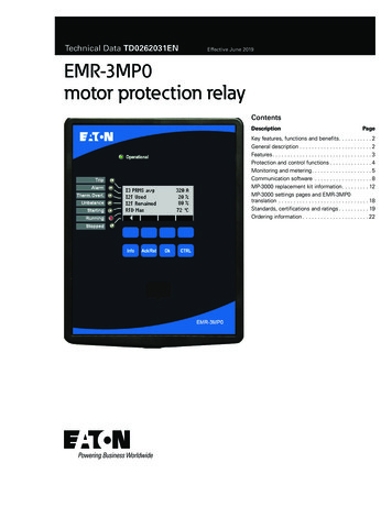
Technical Data TD0262031ENEffective June 2019EMR-3MP0motor protection relayContentsDescriptionPageKey features, functions and benefits. . . . . . . . . . . 2General description. . . . . . . . . . . . . . . . . . . . . . . . 2Features. . . . . . . . . . . . . . . . . . . . . . . . . . . . . . . . . 3Protection and control functions. . . . . . . . . . . . . . 4Monitoring and metering. . . . . . . . . . . . . . . . . . . . 5Communication software . . . . . . . . . . . . . . . . . . . 8MP-3000 replacement kit information. . . . . . . . . 12MP-3000 settings pages and EMR-3MP0translation . . . . . . . . . . . . . . . . . . . . . . . . . . . . . . 18Standards, certifications and ratings. . . . . . . . . . 19Ordering information. . . . . . . . . . . . . . . . . . . . . . 22
EMR-3MP0motor protection relayTechnical Data TD0262031ENEffective June 2019Key features, functions and benefits Microprocessor-based protection with monitoring, and control formedium voltage motors. Integral test function reduces maintenance time and expense. Reduce trouble shooting time and maintenance costs- Trip andevent recording in non-volatile memory provides detailed information for analysis and system restoration. 6000 cycles of waveformcapture aids in post fault analysis (viewable using Powerport-Esoftware) Front USB port and Powerport-E software provides local computer access and user-friendly windows based interface for relaysettings, configuration, and data retrieval. Fast and easy troubleshooting, improved maintenance proceduresand increased device security. Provides detailed traceability forsystem configuration changes Relays self-diagnostics and reporting improves uptime and troubleshooting.General descriptionEaton’s EMR-3MP0 motor protection relay is a multifunctional microprocessor-based protective relay for the protection of any size motorat all voltage levels. It is most commonly applied on medium voltage or larger motors. The EMR-3MP0 relay is a current only devicethat provides complete and reliable motor protection, monitoring,and starting control functions. The EMR-3MP0 has been speciallydesigned to simplify the settings and configuration providing a userexperience very similar to the now obsolete Eaton MP-3000 motorrelay. See pages 12–15 for information on the MP-3000 to EMR3MP0 retrofit relay kit.The EMR-3MP0 motor protection relay has removable terminalblocks, and multiple communications options.The EMR-3MP0 motor protection relay has three-phase and oneground current inputs. It can be used with either a 5A or 1A CTs.The ground protection can be used with either a zero sequenceground CT or from the residual connection of the phase CTs. Thezero sequence ground CT provides greater ground fault sensitivitythan the residual connection. The unit is user programmable for 60Hz or 50 Hz operation.Flash memory is used for the programming and all settings arestored in nonvolatile memory.An integral keypad and display is provided for direct user programming and retrieval of data without the need of a computer. 14 programmable LEDs provide quick indication of relay status.A front USB port is provided for direct computer connection. AnRS-485 communication port on the back is standard for local areanetworking using Modbus-RTU or DNP3. An optional Ethernet portand various protocols are available.The EMR-3MP0 motor protection relay has mass memory for datastorage and a real-time clock with 1 ms time resolution. The relaywill log 300 sequence of event records, 20 detailed trip logs, minimum/maximum values, load profiles, the 5 latest start profiles,motor trending, breaker wear information and oscillography data.The EMR-3MP0 motor protection relay has four discrete inputs and1 fiber optic input, 1 form C, and 2 NO programmable contacts,1 form C healthy contact. It also has 4-20 mA analog output. The unitalso comes with a test mode to force outputs and simulate currents,to facilitate the commissioning of the unit. It can be powered from19 Vdc to 300 Vdc or 40 Vac to 250 Vac auxiliary power.2EATON www.eaton.com
EMR-3MP0motor protection relayTechnical Data TD0262031ENEffective June 2019FeaturesControl functionsProtection features (trip and alarm elements) Transition for reduced voltage starts Incomplete sequence delay Permits numbers of cold starts Limits numbers of starts per hour Anti-backspin time delay Mechanical load shedding Zero speed switch for long acceleration motors Motor stop inputsJam or stall protection (50J[1], 50J[2]) Remote trip inputPhase unbalance negative sequence overcurrent (46[1], 46[2])). Differential trip inputUnderload protection (37[1], 37[2]) Emergency overrideTemperature protection with optional URTD (49/38). Remote open-close (stop-start) Thermal protection (49/51) Locked rotor protection ( 49S/51) Phase overcurrent elements: Two instantaneous elements with timers ( 50P[1], 50P[2] Ground overcurrent elements: Two instantaneous measured elements with timers (50X[1],and 50X[2]) Communication features Stars per hour (66) Lockout protection (86). Local HMI.Trip bypass (50BF). Password protected. Addressable. Local communication port. USB Remote communication port: RS-485 terminals Metering features Amperes: positive, negative and zero sequence. Ampere demand. % THD I. Magnitude THD I. Minimum/maximum recording Temperature with remote URTD moduleMonitoring features Ethernet RJ45 Fiber optic ST RS-485 D-SUB LC duplex fiber optic Oscillography (6000 cycles total). Fault data logs (up to 20 events).Protocols: Modbus-RTU Sequence of events report (up to 300 events). Modbus-TCP Trending (load profile over time) IEC-61850 Motor history DNP3-RTU Records the last 5 motor start profiles. DNP3-TCP/UDP Motor start trending. Profibus-DP CT supervision Clock (1 ms time stamping). Configuration software Powerport-EEATON www.eaton.com3
EMR-3MP0motor protection relayTechnical Data TD0262031ENEffective June 2019Protection and control functionsJam protectionThe Eaton’s EMR-3MP0 motor protection relay has been designedfor maximum motor operation and protection. It permits running themotor close to its design limits while protecting it against excessive heating and damaging overload conditions. The EMR-3MP0field proven protection algorithms were developed based on motordesigns and operating parameters for optimum operation and protection while minimizing nuisance tripping. The EMR-3MP0 motor protection relay utilizes a patented protection algorithm and measurement technique based on proven positive and negative (unbalance)sequence current sampling and true RMS calculations.The user-selectable jam function protects motors that are runningagainst a sudden mechanical jam or stall condition. The commonapplication is on motors used on crushers, chippers, or conveyors.It detects an increase of motor current to a level above full load.Pickup, start, and run timers and a second element for alarm purposes are provided.Intel-I-Trip (I2t) overload protectionThe EMR-3MP0 motor relay features the exclusive Eaton Intel-I-Tripintelligent overload protection system. Intel-I-Trip develops customoverload curves simply from motor nameplate data. Intel-I-Trip protects motors from potentially damaging overload and abnormal operating conditions. The Intel-I-Trip intelligent overload protection featureutilizes field proven measurement techniques and a patented motorthermal protection model. The EMR-3MP0 motor relay’s unique measurement technique samples the current waveforms 36 times percycle, providing accurate measurements of the positive and negativesequence currents. The negative sequence current causes a greaterheating effect on the rotor and has a greater impact on the thermalmodel in the relay. Intel-I-Trip utilizes these measurements in itsmotor model to safely protect the motor against the heating effectsof these currents.Underload protectionThe user selectable underload function is used to detect the loss ofload on the motor. Coupling failure is a common cause for loss ofload. Pickup, start, and run timers and a second element for alarmpurposes are provided.Reduced voltage startingThe EMR-3MP0 motor protection relay provides a transition andincomplete sequence function for reduced voltage starting. The usercan select to transition based on the current level and/or on time.AntibackspinThe stop function is programmable from 2–20%. For certain applications, such as pumping a fluid up a pipe, the motor may be drivenbackward for a period of time after it stops. The EMR-3MP0 relayprovides an antibackspin timer to prevent starting the motor while itis spinning in the reverse direction. The timer begins counting fromthe moment a stop is declared by the relay.The motor thermal model is analogous to a bucket that is being filledand drained at the same time. The fill rate is dependent on the motorcurrents and the drain is based on motor design principles. The sizeof the bucket is equivalent to the thermal capacity associated withthe mass of the motor. Intel-I-Trip integrates these rates and willissue a trip when the thermal capacity is filled.Start control timersIntel-I-Trip features adaptive trip characteristics that adjust the triptimes based on measured motor temperature when RTDs are used.Load sheddingInstantaneous overcurrentThe EMR-3MP0 motor protection relay provides an instantaneousphase overcurrent function to trip the motor for high fault currentlevels and save the fuses. This function can be disabled and hasan adjustable time delay on starting to avoid nuisance tripping oninrush.Phase unbalance protectionMotor supply circuits are often fed through fuses and can be runwith a single-phase fuse blown, referred to as single phasing themotor. The EMR-3MP0 motor protection relay measures the currentunbalance and can be used to alarm or trip the motor before damageoccurs. Pickup, start, and run timers and a second element for alarmpurposes are provided.Ground fault protectionA separate measuring circuit is used to measure ground current. Aground CT is recommended for more sensitive protection againstwinding insulation breakdown to ground. The relay ground circuit canbe connected residually from the three-phase CTs. The ground faultprotection has pickup and time delay set points or can be disabled.4EATON www.eaton.comMotors typically have limits to the number of cold starts, starts perhour period, or time between starts that are permitted without damage. The EMR-3MP0 motor protection relay incorporates these timers to prevent starting the motor beyond its capabilities.The EMR-3MP0 motor protection relay provides a mechanical loadshedding feature that can be used to control an upstream process.The load-shedding function closes a contact on an overload condition to control an upstream process from adding more load until theoverload condition is gone.Emergency overrideThe EMR-3MP0 motor protection relay has a user-programmable feature that will let the operator reset the start inhibitor timers and thermal overload bucket. This function is intended for use in emergencyconditions only, and it may result in motor damage or failure.Long acceleration motorsLarge motors with a high inertia may experience starting currentsthat exceed the locked rotor current and time. The EMR-3MP0 motorprotection relay has logic and provisions for a zero speed switchinput to differentiate between a stall and start condition. If the motoris spinning, then the relay will not trip on the normal locked rotortime allowing the motor to start.Remote/differential tripThe digital inputs can be programmed to accept a contact inputfrom a separate differential relay or other device to trip the motor.This provides local and remote target information and utilizes the tripcontacts of the EMR-3MP0 motor protection relay. It will also recordand log the motor information at the time of the trip.
EMR-3MP0motor protection relayTechnical Data TD0262031ENEffective June 2019Breaker failure or stuck contactorMonitoring and meteringThe EMR-3MP0 motor protection relay includes a breaker failure(50BF, 62BF) or trip bypass function that can be initiated from eitheran internal or external trip signal. This is an independent elementthat can be used to operate a lockout relay or trip an upstreambreaker. The timer must be longer than the breaker operating timeand the protective function reset times.Sequence of events recordsFlexible phase rotationThe EMR-3MP0 motor protection relay can be applied on either anA-B-C or A-C-B phase rotation. A user setting permits correct operation and indication of the actual system configuration.The EMR-3MP0 protection relay records a maximum of 300 eventsassociated with the relay. An event is classified as a change of stateas detected by the relay. These include relay pickups, dropouts, trips,contact closure, alarms, setting changes and self-diagnostic failures.Each event is date and time stamped to a 1 ms resolution. Theevents are stored in a FIFO in chronological order.Trip logThe EMR-3MP0 protection relay will store a maximum of 20 triprecords in a FIFO trip log. Each trip record will be date and timestamped to a 1 ms resolution. The trip log record will include information on the type of fault, protection elements that operated, faultlocation and currents and voltages at the time of the fault.Waveform captureThe EMR-3MP0 motor protection relay provides oscillographyrecording capabilities. The relay will record all measured signalsalong with the binary signals of pickup, trip, logic and contact closures. The EMR-3MP0 relay can record up to 6000 cycles of data.The number of records is proportional to the size of each record; themaximum size per record is 600 cycles. The waveform capture is initiated by up to 8 different triggers; it can also be generated manuallythrough the display or via communications.Integral user interfaceThe front panel user interface has a 128 x 64 pixel LCD display withbackground illumination for wide angle viewing in all light conditions. 7 programmable LEDs provide quick and easy visual display ofpower on, mode of operation, alarm and trip indication. Soft keys areprovided for operation mode selection, scrolling through data andsettings. In addition, the relay settings and test functions are password protected.Starting profilesThe EMR-3MP0 records the average current versus time for the lastfive starting cycles. This information is available via the communications port through Powerport-E.Motor statisticsFor each motor start, the EMR-3MP0 stores a motor start report andadd this data to the motor statistics buffer. With the motor statisticsyou can track motor start data for the past eighteen 30-day periods.For each 30-day interval, the relay records the following information: The date the interval began The total number of starts in the interval The averages of the following quantities: Motor start time Start % rotor thermal capacity used Maximum start currentEATON www.eaton.com5
EMR-3MP0motor protection relayTechnical Data TD0262031ENEffective June 2019Typical AC connection 5A CTs, and ground current measured by Zero Sequence CT.3-phase, 3-wire IG measure standard 1/5A removable CT blockL1L2L3EMR-3MP0I ̲L1'I ̲L1I ̲L2'I ̲L2I ̲L3'I ̲L31A5AIL1N1A5AIL2N1A5AIL3N1A5AIGNIGEMR-3MP0 F31IG meas X3.1234567891011123-phase, 3-wire IG measure MP compatible 5A fixed CT blockL1L2L3EMR-3MP0X35AH1AI ̲L1'H2AI ̲L15AH1BI ̲L2'5AH1CI ̲L3'I ̲L35AG1G2IGEMR-3MP0 F32IG meas Figure 1. Typical AC connections. 5A CTs, and ground current measured by Zero Sequence CT.EATON www.eaton.comIL3NH2C6IL2NH2BI ̲L2IL1NIGN
EMR-3MP0motor protection relayTechnical Data TD0262031ENEffective June 2019Functional ent Phasors49/ 49S/ rmFaultStartTrendManual Trigger50XURTD Assembly14IRIG-B00XURTD AssemblySNTPEMR-3MP0 F01RTDS tandardProgrammableLogicAnalog OutputHistoryFunctionRTD (ANSI 26/38/49): requires URTD box (separate hardware)Figure 2. Functional overview.Typical control diagramL3L3L2L2L1L1CTsMainFuseGFCTMCT3MBT2Under ControlMATo Motoror Load DeviceT1X1 X2GndGndGndPrimaryFusesNon-CurrentCarrying GroundCPTSecondaryFusesSTARTAC Supply X1-3To EMR-3MP0STOPAdditionalControlMRelay-3*X2-8 X2-9MRelay-1X2-3Alarmrelay has to be a normally open*toThisensurethat protection is enabledwhen motor is started.X2-4Relay-2X2-5EMR-3MP0EMR-3MP0 FC1X1-2X1-1GndAuxiliary TripX2-6Figure 3. Typical control diagram.EATON www.eaton.com7
Technical Data TD0262031ENEffective June 2019Communication softwareEaton provides PowerPort-E configuration software. It runs on aPC or laptop for easy access to a single relay to change set pointsor configuration and to view metered values and stored data.PowerPort-E is free and can be downloaded from the Eaton web siteat the following URL:www.Eaton.com/prPowerport-E- EMR-3MP0 relay settingsFigure 4. Powerport-E - EMR 3MP0 settings.8EATON www.eaton.comEMR-3MP0motor protection relay
EMR-3MP0motor protection relayTechnical Data TD0262031ENEffective June 2019Load profiling/trendingThe EMR-3MP0 relay automatically records selected quantities intonon-volatile memory every 5, 10, 15, 30, or 60 minutes, dependingon the trending report setting.Programmable I/OThe EMR-3MP0 motor protection relay provides heavy-duty, triprated, 2 normally open and 2 form C contacts. One form C contactis dedicated to the relay failure alarm function and is operated in anormally energized (failsafe) mode. There are 4 discrete inputs thataccept 120VAC inputs.DrillingFigure 5. Drilling plan.EATON www.eaton.com9
Technical Data TD0262031ENEffective June 2019Projection mount front and side viewsFigure 6. Projection mount front and side views.10EATON www.eaton.comEMR-3MP0motor protection relay
EMR-3MP0motor protection relayTechnical Data TD0262031ENEffective June 2019Standard mount front and side viewsFigure 7. Standard mount front and side views.EATON www.eaton.com11
EMR-3MP0motor protection relayTechnical Data TD0262031ENEffective June 2019MP-3000 replacement kit informationThe MP-3000 replacement kit consists of 3 parts; EMR-3MP0 relay,cutout adapter panel and conversion box assembly. This kit is denoted by the -1 at the end of the EMR-3MP0 catalog number (see page22). Please see the information below for details in installing the kit.Standard MP-3000/retrofit cutout and drilling pattern5.380 [136.65]9.380 [238.25]4.690 [119.13]2.225 [56.52]4.450 [113.03]6.675 [169.55]8.900 [226.06]2.690 [68.33]0.062 R AD[1.59]4 P LAC E S2.531 [64.29]5.062 [128.57]P ANE L C UT OUTDIME NS IONS IN INC HE S [MM]Figure 8. Drilling pattern.12EATON www.eaton.com0.203 DIA[5.16]10 P LAC E S
EMR-3MP0motor protection relayTechnical Data TD0262031ENEffective June 2019Basic installation steps for replacing MP-3000 with EMR-3MP0. See“MP-3000 to EMR-3MP0 installation instructions” at eaton.com/EMRunder Resources Installation instructions for more information.Step 1: Mount EWR-3MP0 into existing MP3000 cutout.Figure 9. Mount EWR-3MP0 into existing MP3000 cutout.Step 4: Slide the conversion box assembly down into the relay body.Figure 10. Slide the conversion box assembly down into the relay body.EATON www.eaton.com13
Technical Data TD0262031ENEffective June 2019Standard mount side viewFigure 11. Step 6 - Secure conversion box assembly ground wire to relay ground stud.See “MP-3000 to EMR-3MP0 installation instructions” ateaton.com/EMR under Resources Installation instructions for fullinstallation instructions.14EATON www.eaton.comEMR-3MP0motor protection relay
EMR-3MP0motor protection relayTechnical Data TD0262031ENEffective June 2019Conversion box internal wiring between MP3000 compatible terminals and EMR-3MP0 terminals.MP3000 EMR-3MP0EMR-3MP0 MP3000 4/20 mA OUTPUT2514Out 23SHIELD-4/20 mA OUTPUT2415Ou
The EMR-3MP0 motor protection relay can be applied on either an A-B-C or A-C-B phase rotation . A user setting permits correct opera-tion and indication of the actual system configuration . Monitoring and metering Sequence of events records T