Transcription
269MOTOR MANAGEMENT RELAY Instruction ManualFirmware Rev.: 269P.D6.0.4Manual P/N: 1601-0013-D3Copyright 1999 GE MultilinCANADA215 Anderson Avenue, Markham, Ont., L6E 1B3Tel: (905) 294-6222 Fax: (905) 201-2098Internet: http://www.ge.com/edc/pm
TABLE OF CONTENTS1 INTRODUCTION1.1 Motor Protection Requirements.1-11.2 269 Relay Features.1-11.3 Typical Applications .1-11.4 Order Code/Information .1-31.5 Technical Specifications.1-42 INSTALLATION2.1 Physical Dimensions .2-12.2 Mounting .2-62.3 External Connections.2-62.4 Control Power. 2-122.5 Phase CT Inputs. 2-122.6 Ground CT Input. 2-152.7 Trip Relay Contacts . 2-152.8 Alarm Relay Contacts . 2-162.9 Auxiliary Relay #1 Contacts . 2-162.10 Auxiliary Relay #2 Contacts . 2-162.11 RTD Sensor Connections . 2-172.12 Emergency Restart Terminals . 2-182.13 External Reset Terminals . 2-182.14 Analog Output Terminals(Non-Isolated). 2-182.15 Programming Access Terminals. 2-182.16 Display Adjustment. 2-192.17 Front Panel Faceplate. 2-192.18 269 Drawout Relay . 2-192.19 Meter Option Installation . 2-233.24 Statistical Data Features . 3-583.25 Factory Setpoints . 3-583.26 Meter Option . 3-584 TESTING4.1 Primary Injection Testing . 4-14.2 Secondary Injection Testing. 4-14.3 Phase Current Input Functions . 4-14.4 Ground Fault Current Functions . 4-44.5 RTD Measurement Tests . 4-44.6 Power Failure Testing. 4-54.7 Analog Current Output . 4-54.8 Routine Maintenance Verification. 4-54.9 Dielectric Strength (Hi-Pot) Test. 4-55 THEORY OF OPERATION5.1 Hardware . 5-15.2 Firmware. 5-16 APPLICATION EXAMPLES6.1 269 Relay Powered from One of MotorPhase Inputs . 6-16.2 Loss of Control Power Due to Short Circuitor Ground Fault. 6-16.3 Example Using FLC Thermal CapacityReduction Setpoint . 6-1APPENDIX A3 SETUP AND USE3.1 Controls and Indicators.3-23.2 269 Relay Display Modes .3-63.3 ACTUAL VALUES Mode .3-63.3a Starts/Hour Timer . 3-163.3b Time Between Starts Timer . 3-163.3c Cause of Last Trip. 3-163.3d Cause of Last Event. 3-163.4 SETPOINTS Mode. 3-163.5 HELP Mode . 3-413.6 TRIP/ALARM Mode . 3-413.7 Phase CT and Motor Full Load CurrentSetpoints . 3-443.8 Acceleration Time Setpoint . 3-443.9 Inhibits . 3-443.10 Unbalance Setpoints. 3-453.11 Ground Fault (Earth Leakage)Setpoints . 3-463.12 Undercurrent Setpoints . 3-493.13 Rapid Trip / Mechanical Jam Setpoints 3-493.14 Short Circuit Setpoints . 3-503.15 Immediate Overload Alarm LevelSetpoint. 3-503.16 Stator RTD Setpoints . 3-503.17 Other RTD Setpoints. 3-513.18 Overload Curve Setpoints . 3-513.19 Thermal Capacity Alarm . 3-553.20 Thermal Memory . 3-553.21 Emergency Restart . 3-563.22 Resetting The 269 Relay. 3-573.23 269 Relay Self-Test. 3-57269 UNBALANCE EXAMPLE . A-1APPENDIX B269 Thermal Model . B-1269 RTD Bias Feature. B-2APPENDIX C269 RTD Circuitry .C-1APPENDIX D2φ CT Configuration .D-1APPENDIX EAsymmetrical Starting Current . E-1APPENDIX F269 Do's and Don'ts Checklist . F-1APPENDIX GGround Fault and Short Circuit InstantaneousElements. G-1APPENDIX HI. 269 CT Withstand .H-1II. CT Size and Saturation .H-1APPENDIX I269 Commissioning Summary .I-1i
TABLE OF CONTENTSGLOSSARYii
1 INTRODUCTION1.1 Motor Protection RequirementsThree phase AC motors have become standard inmodern industry. These motors are generally ruggedand very reliable when used within their rated limits.Newer motors, however, tend to be designed to runmuch closer to these operational limits and thus, thereis less margin available for any type of abnormal supply, load, or operating conditions.In order to fully protect these motors, a modern protective device is required. Accurate stator and rotor thermal modeling is necessary to allow the motor tooperate within its thermal limits and still give the maximum desired output. As well, other features can beincorporated into a modern relay to fully protect themotor, the associated mechanical system, and themotor operator from all types of faults or overloads.Motor thermal limits can be exceeded due to increasedcurrent from mechanical overloads or supply unbalance. Unbalance can greatly increase heating in therotor because of the large negative sequence currentcomponents present during even small voltage unbalances. A locked or stalled rotor can cause severeheating because of the associated large currents drawnfrom the supply. Many motor starts over a short periodof time can cause overheating as well. Phase-to-phaseand phase-to-ground faults can also cause damage tomotors and hazards to personnel. Bearing overheatingand loss of load can cause damage to the mechanicalload being driven by the motor.The ideal motor protection relay should monitor therotor and stator winding temperatures exactly and shutoff the motor when thermal limits are reached. Thisrelay should have an exact knowledge of the temperature and proper operating characteristics of the motorand should shut down the motor on the occurrence ofany potentially damaging or hazardous condition.The GE Multilin Model 269 Motor Management Relay uses motor phase current readings combined with stator RTD temperature readings to thermally model themotor being protected. The relay also monitors themotor and mechanical load for faults and problems.With the addition of a GE Multilin meter (MPM), the269 may also monitor voltages and power and performseveral protection functions based on these values.alphanumeric display. A built-in "HELP" function caninstruct the user on the proper function of each of theprogramming keys and on the meaning of each displayed message.One 269 relay is required per motor. Phase andground fault currents are monitored through currenttransformers so that motors of any line voltage can beprotected. The relay is used as a pilot device to causea contactor or breaker to open under fault conditions;that is, it does not carry the primary motor current.All setpoints are stored in the 269 non-volatile memorywithin the relay. Thus, even when control power is removed from the 269, all relay setpoints and pre-tripvalues will remain intact.The 269 can provide one of various output signals forremote metering or programmable controller attachment. Analog signals of motor current as a percentageof full load, hottest stator RTD temperature, percentageof phase CT secondary current, motor thermal capacity, or bearing temperature are available by simple fieldprogramming. A total of four output relays are providedon the 269, including a latched trip relay, an alarm relay, and two auxiliary relays. All output relays may beprogrammed via the keypad to trip on specific types offaults or alarms.When an output relay becomes active, the 269 will display the cause of the trip, and if applicable, the lock-outtime remaining. Pre-trip values of average and individual line motor current, unbalance, ground fault current,and maximum stator RTD temperature are stored bythe 269 and may be recalled using the keypad.The correct operation of the GE Multilin 269 relay iscontinually checked by a built-in firmware self-test routine. If any part of the relay malfunctions under thisself-test, an alarm indication will tell the operator thatservice is required.1.3 Typical ApplicationsThe many features of the 269 make it an ideal choicefor a wide range of motor protection applications. Versatile features and controls allow the relay to protectassociated mechanical equipment as well as the motor.The 269 should be considered for the following andother typical uses:1.2 269 Relay Features1.Protection of motors and equipment from operatorabuse.The GE Multilin Model 269 Motor Management Relay is a modern microcomputer-based product designed toprovide complete, accurate protection for industrialmotors and their associated mechanical systems. The269 offers a wide range of protection, monitoring, anddiagnostic features in a single, integrated package. Allof the relay setpoints may be programmed in the fieldusing a simple 12-position keypad and 48 character2.Protection of personnel from shock hazards due towinding shorts or earth leakage current frommoisture.3.Protection of gears, pumps, fans, saw mills, cutters, and compressors from mechanical jam.1-1
1 INTRODUCTIONTable 1-1 Model 269 Relay FeaturesProtection Features- Overloads- Stator Winding Overtemperature (Alarm, High Alarm and Trip)- Multiple Starts- Short Circuit- Locked Rotor- Rapid Trip/Mechanical Jam- Unbalance/Single Phasing- Ground Fault (Alarm and Trip)- Bearing Overtemperature (Alarm and Trip)- Undercurrent (Alarm and Trip)- Variable Lock-Out Time- Phase Reversal (Meter Option)Operational Features- Microcomputer controlled- Keypad programmable- 48 character alphanumeric display- Built-in "HELP" function- Eight selectable standard overload curves- Continual relay circuitry self-checkMonitoring and Display Features- Negative sequence phase current unbalance measurement- Ground fault (earth leakage) current measurement- Up to six stator RTD inputs- Two additional RTD inputs- Monitoring of motor ambient air temperature- Display of all SETPOINTS or ACTUAL VALUES upon request- Display of relay TRIP/ALARM and HELP messagesCommunications and Control Features- One latched, main trip relay- One alarm relay- Two auxiliary relays- Emergency restart capability- Pre-trip alarm warnings- 4-20mA output of motor current as a percentage of full load, motor thermal capacity, hottest stator RTD temperature, percentage of phase CT secondary current, or bearing RTDStatistical and Memory Features- Recall of all pre-trip motor values- Tamperproof setpoints stored in non-volatile memory- Microcomputer "learns" motor inrush current- Accumulation of motor running hoursVoltage and Power Metering (available with MPM)- Display of 3 phase or line voltages, kWatts, kVars, Power Factor, and frequency.- Protection features based on Voltage, Power Factor, kVars, and voltage sensed phase reversals.- Pre-trip values of average voltage, kWatts, kVars, Power Factor, and frequency.- Accumulated MegaWattHours.4.Protection for loss of suction for pumps or loss ofair flow for fans using the undercurrent feature.5.Protection of motor and load bearings from excessive heat buildup due to mechanical wear.6.Protection of motors operated in environments withvarying ambient temperatures.7.Complete protection, allowing maximum motorutilization with minimum downtime, for all AC motors.1-2
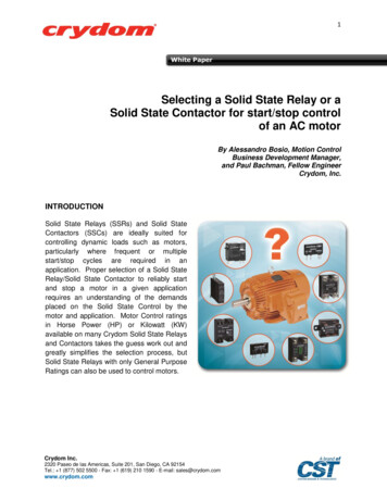
1 INTRODUCTION1.4 Order Code/InformationThe model 269 relay is almost entirely field programmable. The information shown above must be specified when the relay is ordered, as these options are notselectable in the field. Additional features can be madeavailable on special order by contacting the GE Multilinfactory.* CT information, failsafe code, and contact arrangement must be specified for drawout relaysonly; on standard 269's these features are fieldselectable.** See Glossary for definitions1-3
1 INTRODUCTION1.5 Technical SpecificationsPhase Current Inputsconversion: calibrated RMS, sample time 2msrange:0.05 to 12 phase CT primary amps setpointfull scale:12 phase CT primary amps setpointaccuracy: 0.5% of full scale(0.05 to 2 phase CT primary amps setpoint) 1.0% of full scale(over 2 phase CT primary amps setpoint)Frequency: 20–400 HzGround Fault Current Inputconversion: calibrated RMS, sample time 2msrange:0.1 to 1.0 G/F CT primary amps setpoint (5 Amp secondary CT)1.0 to 10.0 amps 50:0.025A (2000:1 ratio)full scale:1 G/F CT primary amps setpoint(5 Amp secondary CT)10 amps (2000:1 CT)accuracy: 4% of G/F CT primary amps setpoint(5 Amp secondary CT) 0.3 amps primary (2000:1 CT)Frequency: 20–400 HzOverload Curvescurves:8 curves fixed shapetrip time accuracy: 1 sec. up to 13 sec. 8% of trip time over 13 sec.detection level: 1% of primary CT ampsUnbalancedisplay accuracy: 2 percentage points of true negativesequ
1.2 269 Relay Features The GE Multilin Model 269 Motor Management Relay .