Transcription
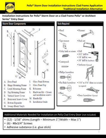
Pella Storm Door Installation Instructions Clad Frame ApplicationTraditional Installation AlternativeInstallation instructions for Pella Storm Door on a Clad Frame Pella or ArchitectSeries Entry DoorAdditional Materials Needed for Installation on Pella Clad Entry Door (not included) (12) - 1/16” shims (Length – Minimum 1”/Width – Max 1”) (6) - #8x3/4” Screws Adhesive substance (i.e. glue stick)1
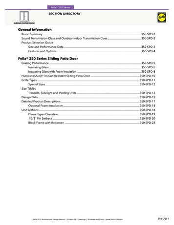
Installation will require two or more persons for safety reasons.Remember to use appropriate personal protective equipment.1 HingingBefore you begin, determine the side you want your door to hinge (left or right)NOTE: When making this determination, make sure the handle on thestorm door will not interfere with the handle on the primary door. If theprimary door hardware is at the same height, it may interfere and werecommend you hinge the storm door on the opposite side.*The following images are shown with left hinge orientation2
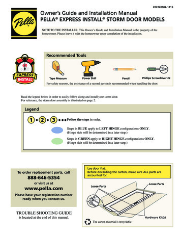
2 HINGE MOUNTING FRAMEABL1Determine the finished length of the mounting frame.Facing the house from the outside, measure theheight of the opening as illustrated in 2B. Thismeasurement is taken from the top of the dooropening down to the bottom threshold.CTake two measurements (L1 and L2) as shown anddeduct 1/8” from each to determine the thresholdangle to cut the mounting frame.DStarting at the top of the hinge mounting frameand working toward the bottom, measure andmark the lengths taken from the previous step.E2BMatching the angle of your entryway sill, cut thebottom of the hinge mounting frame to length. See 2E.*For a simplified installation, a straight cut at L1 maybe made.2E*Door is shown attached to hinge mounting frame for illustrative purposes. Door should not beattached when you cut the frame.3
2 HINGE MOUNTING FRAME - CONTINUEDFGAdhere 1/16” shims to hinge side mountingframe. Shims should be applied directly overpre-drilled holes on the interior side of thehinge mounting frame. Align shims with edge ofhinge mounting frame.Edge2FPress the hinge mounting frame against the hingeside of the clad entry door frame. Rest themounting frame on the sill of the entry door.2HHClamp or hold hinge mounting frame to clad frame to hold framesteady. Be careful not to clamp too tightly and damage the frame.* To create a flat surface for the clamp, place shim between clamp andframe.IHold frame steady and pre-drill all hinge side holelocations into the jamb with a 3/32” drill bit.JContinue holding frame steady and pre-drill all holes on faceside of hinge mounting frame.K*If your entry door has clad brickmould, some brickmould will be visiblethrough the holes. Drill through the holes.*By drilling pilot holes first, you are ensuring the storm door will beplaced in the appropriate location.2IRemove hinge mounting frame to attach to door.4
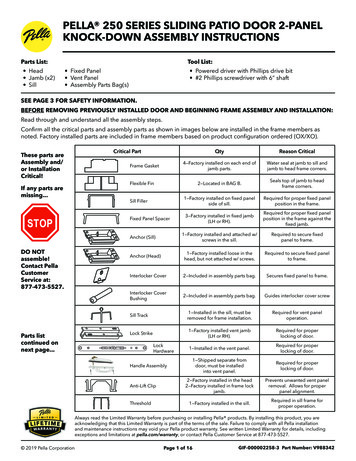
2 HINGE MOUNTING FRAME - CONTINUEDLWith the interior of the door facing up, position the hinge mounting frameon the door panel.*Notice the location of the weatherstripping.*If applicable, you may remove glass or screen from storm door for easier handling.MAlign the pre-drilled alignment mark with the outer hinge hole and installone hinge screw (#8 x 3/4" hex head).NCheck to ensure there is a 3/16"-1/4"overhang from the highest point ofthe top of the door.* If the hinge side mounting frame extends more than or less than 3/16"1/4" above the top of the door panel, remove the hinge screw. Position thehinge side mounting frame to achieve the correct overhang, andcenterpunch and drill a new 1/8" diameter hole through one of the otherhinge holes.Install the (#8 x 3/4" hex head) hinge screw in the new hole.OAlign the hinge holes with the score line.PDrill the remaining hinge holes using an 1/8” bit and install.5
3 INSTALL EXPANDER SWEEPSARemove the expander from the door.BInstall the sweep by threading it into the channel of theexpander. While bending the sweep out of the way, crimpboth ends of the expander channel with pliers to hold thesweep locked in position. For best results crimp the inner legof the channel only. Cut off any excess sweep material.CInstall the expander.DInstall expander on the bottom of the door so the holes arelocated on the inside of the door. Do not fasten expanderto the door at this time.4 INSTALL THE DOORNote: The illustrations show the installation of a left hinge door. Right hinge doors are installedwith the hinges to the right side of the entryway opening when viewed from the exterior.ABSet the door in the entryway opening resting thehinge side mounting frame on the sill. Slide thehinge frame (with attached shims) tight against theentry door jamb. The holes in the mounting frameshould align with the pilot holes drilled in steps 2Iand 2J.Loosely install three face screws to hold the unitin place, using the pilot holes. Do not fully seatthe face screws.COpen Door.DDrive the hinge screws through the pre-drilledholes on the hinge side.EClose Door.FTighten face screws from step 4B and installremaining face screws.4B4D4F*Do not over tighten face screws.6
5 TOP MOUNTING FRAMEABCWith the door open, position the top mounting frame so it rests on the hingemounting frame.Close the door and align the end of the top mounting frame with the outer edge ofthe hinge mounting frame. Position to achieve a uniform gap between the topmounting frame and the door.Drill a 3/32" diameter hole through each pre-drilled hole of the top mountingframe. Secure the top mounting frame with the mounting frame screws (#6 x 1"Phillips pan head).*Drill and install the hinge side screw first.6 LATCH MOUNTING FRAMEABMeasure the latch side height from the underside of the topmounting frame to the sill (see L3 and L4) and deduct 1/8”from each.*Measure entryway with brickmould at the point where thebrickmould attaches to the entry door frame.Starting at the top of the latch mounting frame, mark off yourmeasurement (see 6A) and cut to length matching the angle of the sill.*Notice the position of the weatherstripping.*Copy the cuts made in step 2E.7
6 LATCH MOUNTING FRAME - CONTINUEDCAdhere 1/16” shims to inside of latch mounting frame oneinch above mounting holes on adjacent side.*See image on right.DPosition the latch mounting frame in the entryway opening. Lineup the exterior end of the latch side mounting frame with theend of the top mounting frame.Edge6CAt each location where shims were placed, pre-drill holesthrough mounting frame, shims and clad entry door frame.EWhen pre-drilling holes, position hole location ¼” from the pileweatherstrip.*This is the same distance the screws were placed on the hinge mountingframe.FGInstall screws through new pilot holes (#8 x 3/4).6G*Make sure your marks are still aligned on the face side.Beginning at the top hole, drill a 3/32" diameter hole through thepre-drilled hole of the face side of latch mounting frame. Be surethe edge of door panel and the mounting frame are aligned fromtop to bottom. Install a mounting frame screw (#6 x 1" Phillipspan head) in each hole.7 BOTTOM EXPANDER ADJUSTMENTABC8Close the door and adjust the bottom expander so that the vinyl sweeps touchthe door threshold. The slotted holes in the expander should be located on theinside of the door.From the interior, drill a 3/32" hole in the center of each slot of the bottom expander.Drill through the bottom expander and interior surface of the door.Install a bottom expander screw (#6 x 3/8" Phillips pan head) in each end.*Use a hand screwdriver to secure the expander. DO NOT use a power screwdriver.DOOR HARDWAREATo install the handle assembly, refer to the separate instruction sheet included in the handlehardware box.*For mortise hardware you may need to reverse latch assembly. See Hardware instructions.8
9 INSTALL WINDOW HANDLE (On Applicable Models)AInstall spring into bottom of handle.9A9C9ABTo install handle onto window, open top window to acomfortable height for handle installation.CSlide the handle (with the spring installed and facing down)into the top rail channel starting at the left side of the topof the operating glass.*The spring may need to be compressed slightly to allow the handleto slide into the channel.9CDCenter handle on window rail.ESlide the handle past the first (left) notch. There will besome resistance. THEN STOP! (Figure 9E)*The handle should not go past the second (right) notch (Figure 9E).FLeft notch will be visible when handle installation iscomplete. Right notch will be hidden behind handle.9E9E9
10 CLOSERSAOn the hinge side of your entryway, position a jambcloser bracket even with the top of the expander, (seethe dotted line in the illustration) and 1/4" back from themounting frame. Mark the screw hole locations and drill1/8" diameter holes.BInstall the bottom jamb closer brackets using four jambbracket screws (#10 x 1-1/2" Phillips pan head) for eachbracket.CAttach the bottom closer (with One-Touch button) rod to the jamb bracket using the shortcloser pin, then pull the door closer and slide theSHORT spacer clip onto the closer rod as shown.Rotate the closer so the One-touch button isalong the top of the closer.DAttach the door closer bracket to the door closer,by removing the O-ring and pin, then reinsertingthe pin.EWith the door tightly closed, align the bottomdoor closer bracket with the top of the bottomexpander. Mark the centers of the hole pattern.Center punch and drill 1/8" diameter holesthrough the interior face of the door.FInstall the door closer bracket with two door closerbracket screws (#10 x 5/8" Phillips pan head).10A10
10 CLOSERS - CONTINUEDGDiscard spacer clip from the closer rod.HMeasure the distance from the hinge side of theentryway, to the end of the bottom door closerbracket.IMeasure and mark this distance for the top closer,just above the screen head cover.JRest the door closer bracket on top edge of thescreen head cover, and position the end of thedoor closer bracket on the mark from step I. Markthe screw locations for the top door closer bracket.Center punch and drill 1/8" diameter pilotholes.KInstall the top door closer bracket with two doorcloser bracket screws (#10 x 5/8" Phillips panhead).LAttach the door closer bracket to the door closer,by removing the O-ring and pin, then reinsertingthe pin.MAttach the top closer rod to the jamb bracket usingthe short closer pin (10J, 10M).10J11
10 CLOSERS - CONTINUEDNOHolding the closer level, position the jamb closerbracket against the entryway jamb. Ensure thejamb closer bracket is 1/4" back from the hingeside mounting frame, mark the mounting screwlocations and drill 1/8“ diameter pilot holes.Install the top jamb closer bracket using four jambbracket screws (#10 x 1-1/2" Phillips pan head) foreach bracket.* Removing the door jamb bracket from the closer maymake installation of the bracket easier.POpen the door and check the closer speed. Thespeed of each closer may be adjusted by turningthe adjustment screw. Turn the screw clockwise toreduce the closer speed or counter clockwise toincrease the closer speed.QTo use the One-Touch Button: Tap the button andopen the door. To close, nudge the door openslightly.11 SCREW COVERSAStarting flush at one end, install the horizontal screw cover strip byinserting the angled edge into the outer most track and pressing inplace. Repeat this procedure for the two vertical screw coversstarting at the top of the mounting frames.*Cut the vertical screw covers to match the length of the mounting frame byscoring with a utility knife, then snapping in two.12
WithL the interior of the door facing up, position the hinge mounting frame on the door panel. *Notice the location of the weatherstripping. *If applicable, you may remove glass or screen from storm door for easier handling. AlignM the pre-drilled alignment mark with the outer hinge hole and install one hinge screw (#8 x 3/4" hex head).