Transcription
Operating Guide
Intended to alert the user to the presence of uninsulated “dangerous voltage” within the product’senclosure that may be of sufficient magnitude to constitute a risk of electric shock to persons.Intended to alert the user of the presence of important operating and maintenance (servicing)instructions in the literature accompanying the product.CAUTION: Risk of electrical shock — DO NOT OPEN!CAUTION: To reduce the risk of electric shock, do not remove cover. No user serviceable parts inside. Referservicing to qualified service personnel.WARNING: To prevent electrical shock or fire hazard, do not expose this appliance to rain or moisture. Beforeusing this appliance, read the operating guide for further warnings.Este símbolo tiene el propósito, de alertar al usuario de la presencia de “(voltaje) peligroso” sin aislamiento dentro de la caja del producto y que puede tener una magnitud suficiente como para constituirriesgo de descarga eléctrica.Este símbolo tiene el propósito de alertar al usario de la presencia de instruccones importantes sobre laoperación y mantenimiento en la información que viene con el producto.PRECAUCION: Riesgo de descarga eléctrica ¡NO ABRIR!PRECAUCION: Para disminuír el riesgo de descarga eléctrica, no abra la cubierta. No hay piezas útiles dentro.Deje todo mantenimiento en manos del personal técnico cualificado.ADVERTENCIA: Para evitar descargas eléctricas o peligro de incendio, no deje expuesto a la lluvia o humedadeste aparato Antes de usar este aparato, Iea más advertencias en la guía de operación.Ce symbole est utilisé dans ce manuel pour indiquer à l’utilisateur la présence d’une tension dangereusepouvant être d’amplitude suffisante pour constituer un risque de choc électrique.Ce symbole est utilisé dans ce manuel pour indiquer à l’utilisateur qu’il ou qu’elle trouvera d’importantesinstructions concernant l’utilisation et l’entretien de l’appareil dans le paragraphe signalé.ATTENTION: Risques de choc électrique — NE PAS OUVRIR!ATTENTION: Afin de réduire le risque de choc électrique, ne pas enlever le couvercle. Il ne se trouve à l’intérieuraucune pièce pouvant être reparée par l’utilisateur. Confiez I’entretien et la réparation de l’appareil à un réparateurPeavey agréé.AVERTISSEMENT: Afin de prévenir les risques de décharge électrique ou de feu, n’exposez pas cet appareil à lapluie ou à l’humidité. Avant d’utiliser cet appareil, lisez attentivement les avertissements supplémentaires de cemanuel.Dieses Symbol soll den Anwender vor unisolierten gefährlichen Spannungen innerhalb des Gehäuseswarnen, die von Ausreichender Stärke sind, um einen elektrischen Schlag verursachen zu können.Dieses Symbol soll den Benutzer auf wichtige Instruktionen in der Bedienungsanleitung aufmerksammachen, die Handhabung und Wartung des Produkts betreffen.VORSICHT: Risiko — Elektrischer Schlag! Nicht öffnen!VORSICHT: Um das Risiko eines elektrischen Schlages zu vermeiden, nicht die Abdeckung enfernen. Es befindensich keine Teile darin, die vom Anwender repariert werden könnten. Reparaturen nur von qualifiziertemFachpersonal durchführen lassen.ACHTUNG: Um einen elektrischen Schlag oder Feuergefahr zu vermeiden, sollte dieses Gerät nicht dem Regenoder Feuchtigkeit ausgesetzt werden. Vor Inbetriebnahme unbedingt die Bedienungsanleitung lesen.2
ENGLISH5150 IITube Guitar AmplifierCongratulations on your purchase of the all new 5150 II. Peavey’s continuous design collaborationwith guitar icon and legend, Edward Van Halen, has produced yet another feature-packed, monsterguitar head. Like the original 5150 head, the 5150 II offers two channels. However, the 5150 II addsseparate EQ, Resonance, and Presence controls to each channel, giving you more control andflexibility. The new footswitch provides foot control of channel selection, effects loop, and the newlyadded ability to select the Crunch feature. Now you can instantly obtain that extra gain in theRhythm Channel with your foot and never have to take your hand off the guitar. Finally, the CleanChannel has been added, completely redesigned to sound much cleaner, and has one 12AX7devoted to just the Clean/Crunch.The following guide explains these features and how to operate each one in order to obtainyour desired sound. We recommend that you read this manual carefully, paying close attentionto any warnings or cautions.FEATURES: Two distinct tube channels with footswitch control LED “active” indicators for each channel Bright switch for Rhythm channel Crunch switch on Rhythm channel with footswitch control Separate equalizer sections for each channel Separate power amp controls (Resonance and Presence) for each channel Separate preamp controls (Pre and Post Gain) for each channel Standby power switch Bias test points on rear panel Effects loop with footswitch control 1/4" Preamp output jack Speaker impedance selection switch (4, 8, 16 ohm) Two parallel 1/4" speaker output jacks 120 watts output power ohm output power Metal three button footswitch with detachable 25' cable5150 is a registered trademark of Edward Van Halen.3
REAR PANEL FEATURES21310789645POWER(1)LINE CORD:This line cord provides the AC power to the unit. Connect the line cord to a properlygrounded AC supply. Damage to the equipment may occur if improper line voltage is used.(See voltage marking on unit.) Never remove or cut the ground pin of the line cord plug.NOTE: FOR UK ONLYAs the colors of the wires in the mains lead of this apparatus may not correspond with thecolored markings identifying the terminals in your plug, proceed as follows: (1) The wire whichis colored green and yellow must be connected to the terminal which is marked by the letterE, or by the earth symbol, or colored green or green and yellow. (2) The wire which is coloredblue must be connected to the terminal which is marked with the letter N, or the color black.(3) The wire which is colored brown must be connected to the terminal which is marked withthe letter L or the color red.(2)FUSEWARNING: THE FUSE SHOULD ONLY BE REPLACED WHEN THE POWER CORDHAS BEEN DISCONNECTED FROM ITS POWER SOURCE. A 5 amp fuse is located withinthe cap of the fuse holder. It must be replaced with the same type and value in order to avoiddamage to the equipment and to prevent voiding the warranty. If the amp repeatedly blowsfuses, it should be taken to a qualified service center for repair.(3)GROUND SWITCHThis is a three-position, rocker type switch which, for most applications, should be operated inthe center (zero) position. If hum or noise is noticed coming from the speaker enclosure(s)with the Ground Switch in the center position, place the Ground Switch to positive ( ) ornegative (-) to minimize hum. Should a hum/noise problem continue, consult your authorizedPeavey dealer, the Peavey factory, or a qualified service technician.NOTE: THE GROUND SWITCH IS NOT FUNCTIONAL ON 220/240 VOLT MODELS.INs AND OUTs(4)SPEAKER JACKSThese jacks are provided for the connection of speaker enclosure(s). The minimum speakerimpedance is 4 ohms. The Impedance Selector Switch (5) should be set accordingly.(5)IMPEDANCE SELECTOR SWITCH (5)Use this switch to select the appropriate impedance of the speaker enclosure(s) connected tothe Speaker Jacks (4). If two enclosures of equal impedance are used, the switch should beset at one half of that value (e.g., two 16 ohm enclosures: set switch to 8 ohms; two 8 ohmenclosures: set switch to 4 ohms).4
(6)REMOTE FOOTSWITCH JACKThis jack is provided for the connection of the supplied remote footswitch. The footswitchcable should be plugged in before the amp is powered up. When the footswitch is pluggedinto the Remote Footswitch Jack, the Channel Select switch (14) must be pressed to the “in”position for remote selection of the Lead or Rhythm channel (right footswitch button). The Onand Off operation of Effects (left footswitch button) will work at all times. Remote selection ofCrunch gain boost (center footswitch button) is available only when the Crunch Switch (22) isselected. See page 9 for detailed Footswitch diagram.(7/8) EFFECTS SEND/EFFECTS RETURNSignals are supplied to outboard effects or signal processing units by patching from theEffects Send (7) output into the outboard unit(s) and back into the Effects Return (8) inputusing shielded cables with 1/4" mono phone plugs. Only non-gain effects devices (chorus,reverb, delay, etc.) should be used in the effects loop. If footswitch is used, “Effects” must beselected (LED illuminated) for effects to work.(9)PREAMP OUTThis output can be used to send a preamp signal from the 5150 II to a mixing console, taperecorder, etc., using a shielded instrument cable. Patching from the PREAMP OUT does notaffect the normal operation of the amplifier.BIAS ADJUST SYSTEM(10)BIAS TEST TERMINALSThese terminals, along with the adjustment knob behind the grill are provided to measureand adjust the power amp tubes’ bias. The bias adjustment should only be done by aqualified technician.FRONT PANEL FEATURES131514211622152012171819231124ON STANDBY(11)POWER SWITCH/LEDThis switch supplies power to the unit. Depressed to the “ON” position, the red Power LEDindicator will illuminate above the Power Switch when power is being supplied to the unit.(12)STANDBY SWITCH/LEDThis switch allows the 5150 II to be placed in a non-operational standby mode. When theStandby Switch is activated, the tubes remain hot and ready for instantaneous operation,eliminating warm-up time. The Standby LED indicator above the switch will illuminate whenthe amp is in the operational mode.5
PREAMP(13)INPUTThe 5150 II input jack is designed to accommodate a variety of guitar output levels,regardless of pickup configuration. Due to the extreme high gain capabilities of the 5150 II, itis imperative that you use a premium shielded instrument cable in order to minimize noise.(14)CHANNEL SELECT SWITCHThis switch allows selection of the Rhythm or Lead Channel. Depressing the switch to the “in”position activates the Lead Channel. The red LED next to the Lead Pre control will illuminateto indicate that the Lead Channel is active. In the “out” position, the Rhythm channel isactivated and the green LED illuminates next to the Rhythm Pre control to indicate that theRhythm Channel is active. Channels may be remotely selected using the 5150 II’s footswitch.If remote selection is desired, the Channel Select Switch must be set to the “in” position(Lead Channel). See page 9.(15)CHANNEL SELECT LEDBoth the Rhythm Channel and Lead Channel have these LEDs to indicate which channel isactive. The two Channel Select LEDs are never on at the same time. The channel with itsindicator illuminated is the active channel.(16/20) PRE and POST GAINThe channel Pre (16) and Post (20) Gain controls operate in the same manner for bothchannels. However, the Lead channel does have more pregain than the Rhythm Channel. Inmost applications, the Rhythm channel should be set up with the Pre Gain at the lower“cleaner” settings (0-4) and the Post Gain should be set for overall volume. The Rhythmchannel can be converted to a medium distortion channel by activating the Crunch switch(22). This will more closely match the pre gain of the two channels. The Lead channel shouldbe set up with the Pre Gain at the mid to upper settings (5-10) and the Post Gain should beset for overall volume.(17/18/19) EQUALIZATIONThe 5150 II’s equalization block features passive low, mid, and high EQ that is customtailored for each channel to Edward Van Halen’s specifications. Adjusting the control(s)counterclockwise will result in an attenuation of the signal within the frequency band.(21)BRIGHT SWITCHActivates a preset boost in the treble frequencies (6 dB at 2 kHz) and affects only the RhythmChannel.(22)CRUNCH SELECT SWITCHBoosts the gain of the Rhythm channel to create a medium distortion or in between tone.Depress to the “in” position to activate.(23/24) RESONANCE / PRESENCEUnique to Peavey instrument amplifiers, the Resonance control (23) can be set to boost thegain of the power amp in the low frequencies at the resonance/attenuation point of thespeaker cabinet. In simple terms, the Resonance control works like a low EQ to offset lowend frequency drop out. The Presence control (24) works in the same manner, boosting thehigh frequencies. Experimentation using your particular speaker cabinet, along with personaltaste, will determine your setting for these important controls.6
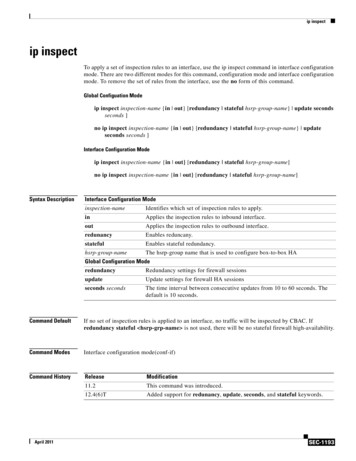
5150 IISPECIFICATIONSPREAMP SECTIONPOWER AMPLIFICATIONSECTIONEFFECTS RETURN:Impedance: Very High Z, 470 k ohmsDesigned Level: -10 dBV, 300 mV RMSThe following specs are measured @1 kHz with the controls preset as follows:Low and High EQ @ 10Mid EQ @ 0Bright outLead and Rhythm Posts @ 10Presence and Resonance @ 0 dBNominal levels with Pre Gains @ 5Minimum levels with Pre Gains @ 10RATED POWER AND LOAD:120 W RMS into 16, 8, or 4 ohmsPOWER @ CLIPPING:(Typically @ 5% THD, 1 kHz, 120 V ACline)130 W RMS into 16, 8, or 4 ohms(Bias must be reduced to measure.)PREAMP OUT:Load Impedance: 47 k ohms or greaterNominal Output: 10 dBV, 3 V RMSREMOTE FOOTSWITCH:Special 3-button unit with LED indicators(supplied)Channel select and reverbPREAMP INPUT:FREQUENCY RESPONSE:Impedance: Very high Z, 470K ohms 0, -3 dB, 50 Hz to 20 kHz @ 100 WRMS into 8 ohmsSYSTEM HUM AND NOISE @NOMINAL LEVEL (clean channel):Lead Channel (with channel select in):Nominal Input Level: -60 dBV,1 mV RMSMinimum Input Level: -76 dBV,.15 mV RMSHUM AND NOISE:Greater than 75 dB below rated powerPOWER AMP EQ:Active Presence: 10 dB @ 2 kHzActive Resonance: 10 dB @ cabinetresonant frequency(20 Hz to 20 kHz unweighted)Greater than 63 dB below rated powerEQUALIZATION:Custom Low, Mid, and High passive type EQPush Bright (Rhythm Channel only) 6 dB @ 2 kHzPush Crunch (Rhythm Channel only)Increases gainClean Channel (with channel select out):Nominal Input Level: -30 dBV,30 mV RMSMinimum Input Level: -34 dBV,20 mV RMSMaximum Input Level: 0 dBV,1.0 V RMS(Subtract 24 dB with Crunch switch in.)POWER CONSUMPTION (Domestic):400 watts 50/60 Hz, 120 V AC(Domestic)TUBE COMPLEMENT:6-12AX7 preamp tubes(1 for clean/crunch, 3 for Lead, 1 forEFX and 1 phase splitter4-6L6GCDIMENSIONS (H x W x D):10" x 26.625" x 11.75"(25.4 cm x 67.6 cm x 29.8 cmWEIGHT:EFFECTS SEND:48.3 lbs. (21.91 kg)Load Impedance: 47 k ohms or greaterNominal Output: -10 dBV, 300 mV RMSFeatures and specifications subject to change without notice.5150 IIBLOCK DIAGRAMPRELOW MID HIPOSTTUBE STAGESLEADFOOTSWITCHEFFECTSTUBE STAGESWITCHLOGICSENDSWITCHLOGICFOOTSWITCHINPUTTUBE BUFFERRETURNCHANNELSELECTTUBE STAGESTUBE STAGESRHYTHMPRELOW MID NAL FLOW BLOCK DIAGRAMRESONANCE PRESENCELEAD7RESONANCE PRESENCERHYTHM
5150 IIHOOKUP DIAGRAM16 Ohms8 OhmsSet switchto 8 OhmsSet switchto 4 Ohms16 Ohms8 OhmsDeltaFex Rack Mount Effects UnitFrom EVH 5150 II EffectsSend Output to Input ofRack Effects UnitEVH 5150 II Back PanelFrom Output of RackEffects Unit to EVH 5150 IIEffects Return InputDelta Stomp Floor PedalFrom EVH 5150 II EffectsSend Output to Input ofEffects PedalFrom Output of Effects Pedalto EVH 5150 II EffectsReturn InputEVH 5150 II Back Panel8
5150 IIRECOMMENDED SETTINGSSouthern Rock/CountryInInSet to proper volumeOutSignature SettingInInInSet to proper volumeActivatesEffects Loopwhen switchis pressedand LEDilluminatesActivatesCrunch Voicingon Rhythmwhen switchis pressedand dchannelsAll switches are push on/push off.There are no momentary switches on the footswitch.*NOTE:Channel select switch (14) must be pressedto the “in” position for this switch to function.9
ESPAÑOLAmplificador de bulbos para guitarra5150 IIFelicidades por tu compra del nuevo 5150 II. La colaboraci n cont¿nua de Peavey con el ¿dolo yleyenda de la guitarra, Edward VanHalen, ha producido un monstruoso cerebro para guitarra llenode nuevas ventajas Como el cerebro 5150 original, el 5150 II ofrece dos canales. Sin embargo, el5150 II a ade controles de Ecualizaci n Separada, Resonancia, y Presencia a cada canal, dßndotemayor control y flexibilidad. El nuevo pedal ofrece control de pie de canales, “loop” de efectos, y lanuva abilidad de seleccionar la funci n de “crunch”. Ahora puedes obtener esa ganancia adicionalen el canal de Ritmo con el pie, sin tener que quitar las manos de la guitarra nunca mßs.Finalmente, el canal limpio ha sido a adido, redise ado completamente para sonar mucho mßslimpio, y tiene un 12AX7 dedicado exclusivamente al limpio/crunch.La siguiente gu¿a explica estas caracter¿sticas y c mo operar cad una para lograr obtener tusonido deseado. Te recomendamos leer el manual cuidadosamente, poniendo atenci n a lasprecauciones y avisos.CARACTER¿STCAS: Dos canales distintivos con control de pedalIndicadores LED “activos” para cada canalSwitch de brillantez para el canal de Ritmo (o acompa amiento)Switch de crunch en el canal de Ritmo con control de pedalSecciones separadas de ecualizador para cada canalControles de amplificador de poder (Resonancia y Poder) para cada canalControles separados de preamp (Pre y Post Ganacia) pra cada canalSwitch de poder “standby”Puntos de prueba de biaas en el panel traseroLoop de efectos con control de pedalSalida de Preamp de 1/4"Switch de selecci n de impedancia para las bocinas (4, 6, 8 ohmios)Dos salidas paralelas de 1/4" para bocinaSalida de 120 wats de salida de poder en ohmiosPedal de tres botones con cable removible de 25'5150 es una marca registrada de Edward Van Halen10
CARACTER¿STICAS DEL PANEL TRASERO21310789645PODER(1)CABLE DE L¿NEA:Est cable de linea provee el poder de CA a la unidad. Conecta el cable a un suministro deCA propiamente aterrizado. Da o al equipo puede causarse si se usa un voltage de lineainapropiado. (Ver marcaci n de voltage en la unidad). Nunca quites el alfiler de tierra delconector del cable de l¿nea.NOTA S¿LO PARA EL REINO UNIDOYa que el color de los cables de este aparato pueden no corresponder a las marcas decolores que identidfican las terminales en tu conector, haz lo siguiente: (1) El alambre verde yamarillo debe de conectarse a la terminal marcada con la letra E, o por el s¿mbolo de tierra,o del color verde o verde y amarillo. (2) El alambre azul debe ser conectado a la terminalmarcada con la letra N , o de color negro. (3) El alambre caf¿ debe conectarse a la terminalmarcada con la letra L o el color rojo.(2)FUSIBLEPRECAUCI¿N: EL FUSIBLE SOLAMENTE DEBE SER REEMPLAZADO CUANDO ELCABLE DE PODER HAY ASIDO DESCONECTADO DE SU FUENTE DE PODER. Un fusibleha sido colocado dentro de la tapa del compartimiento del fusible. Debe ser reemplazado conuno del mismo valor y tipo para evitar alg·n da o al equipo y para no cancelar la garant¿a. Siel amplificador quema fusibles cont¿nuamente, debe ser llevado a un centro de servicio calificado para ser reparado.(3)SWITCH DE TIERRAEste es un switch de tres posiciones que, para la mayor¿a de las aplicaciones, se debeoperar en la posici n central (cero). Si un zumbido o ruido saliera de la(s) bocina(s) con elSwitch de Tierra en la posici n central, pasa el switch a la posici n ( ) (-) para minimizar elzumbido. Si persiste este problema, consulta a un vendedor autorizado de Peavey, a lafßbrica misma, o a un t¿cnico de servicio calificado.NOTA: EL SWITCH DE TIERRA NO FUNCIONA EN LOS MODELOS DE 220/240 VOLTIOS.ENTRADAS Y SALIDAS(4)CONEXIONES PARA BOCINASEstas conexiones sirven para conectar bocina a 5150 II. La m¿nima impedancia es 4ohmios. El Switch Selector de Impedancia (5) debe ser ajustado de manera correspondiente.(5)SWITCH DE SELECTOR DE IMPEDANCIAUsa este switch para seleccionar la impedancia apropiada de la bocina o bocinas conectadaa las conexiones para bocinas (4). Si dos gabinetes con la misma impedancia son usados, el11
switch debe ser ajustado a la mitad de ese valor, por ejemplo: dos gabinetes de 16 ohmios:ajustar switch a 8 ohmios; dos gabinets de 8 ohmios: ajustar switch a 4 ohmios.(6)ENTRADA PARA PEDAL REMOTOEste pedal se proporciona para para la conexi n del pedal remoto inclu¿do. El cable delpedal debe ser conectado antes de que se prenda el ampli. Cuando es conectado el pedalsu entrada, el Switch de Selecci n de Canal (14) se debe presionar para quedar oprimidopara la selecci n remota del canal “Lead” o “Rhythm” (bot n derecho del pedal). La operci nde Encendido y Apagado de Efectos (bot n izquirdo del pedal) funcionarß en todo momento.La selecci n de la ganancia de “Crunch” (bot n central del pedal) s lo estß disponiblecuando est¿ seleccionado el Switch de Crunch (22). Ver la pßgina 9 para un diagramadetallado del pedal.(7/8) ENV¿O Y RETORNO DE EFECTOSLa se ales son enviadas a unidades perif¿ricas de efectos al parchear la salida de Env¿o deEfectos (7) a las unidades perif¿ricas y de regreso a la entrada del Retorno de Efectos (8)usando cables blindados monof nicos con conectores de 1/4". S lo efectos sin ganancia(chorus, reverb, delay, etc.) deben ser usados en el “loop”. Si se usa el pedal, debeseleccionarse “Effects” (led iluminado) para que los efectos funcionen.(9)SALIDA DE PREAMPEsta salida puede ser usada para mandar una se al de preamp del 5150 II a una consola,grabadora, etc., usando un cable brindado de instrumento. El parchear desde la SALIDA DEPREAMP no afecta la operaci n normal del amplificador.SISTEMA DE AJUSTE DE BIAS(10)TERMINALES DE PRUEBA DE BIASEstas terminales, junto con la perilla de ajuste que se encuentra detrßs de la parrilla sirvenpara medir y ajustar el bias de los bulbos del amplificador de poder. El ajuste del bias s lodebe ser llevado a cabo por un t¿cnico calificado.CARACTER¿STICAS DEL PANEL FRONTAL131514211622152012171819231124ON STANDBY(11)SWITCH/LED DE PODEREste switch le da poder a la unidad. Oprimido en la posici n “on”, el LED rojo de Poder seiluminarß arriba del Switch de Poder cuando la unidad sea suministrada con poder.(12)SWITCH/LED “STANDBY”Este switch permite que el 5150 II se coloque en un modo no operacional. Cuando se activael switch de stanby, los bulbos permanecen calientes y listos para una operaci n12
instantßnea, eliminando el tiempo de calientamiento. El indicador led de Standby arriba delswitch se iluminarß cuando el ampli est¿ en modo operacional.PREAMPLIFICADOR(13)ENTRADALa entrada del 5150 II estß dise ada para recibir una variedad de niveles de salida deguitarras, sin importar la configuraci n de las pastillas. Debido a la capacidad de gananciasextremadamente altas del 5150 II es imperativo que uses un cable blindado de instrumentode la mßs alta calidad para minimizar el ruido.(14)SWITCH DE SELECCI¿N DE CANALEste switch permite la selecci n de los canales de acompa amiento o l¿der. El switch en laposici oprimida activa el canal l¿der. El LED rojo que estß junto al control “Lead Pre” seiluminarß para indicar que el canal l¿der estß activo. En la posici n no oprimida, el canal deacompa amiento (rhythm) es activado y el LED verde se iluminarß junto al control “RhythmPre” para indicar su activaci n. Los canales pueden ser activados remotamente usando elpedal del 5150 II. Si se desea esta secci n remota, el Switch de Selecci n de Canal debeestar en la posici n oprimida (canal L¿der). Ver pßgina 9.(15)LED DE SELECCI¿N DE CANALTanto el canal de acompa amiento com el l¿der, tienen estos LEDs para indicar qu¿ canalestß activo. Estos dos LEDs nunca estßn prendidos al mismo tiempo.(16/20) GANANCIA PRE Y POSTLos controles de ganancia de los canales Pre (16) y Post (20) operan de la misma manerapara ambos canales. Sin embargo, el canal l¿der s¿ tiene mßs pre ganancia que el canal deacompa amiento. En la mayor¿a de las aplicaciones el canal de acompa amiento debe deajustarse con la pre ganancia a los valores mßs “limpios” (0-4) y la post ganancia debe serajustada para un volumen general. El canal de acomap amiento puede ser convertido a unadistorsi n mediana activando el switch Crunch (22). Esto igualarß mßs de cerca la preganancia de los dos canales. El canal l¿der debe ser ajustado con la pre ganancia en losvalores medios a altos (5-10) y la post ganancia debe ser ajustada para un volumen general.(17/18/19) ECUALIZACI¿NEl bloque de ecualizaci n del 5150 II presenta ecualizaci n de bajas medias y altasfrecuancias que estß dise ado espec¿ficamente para cada canal por Edward Van Halen. Siajustas los controles en direcci n contraria a las manecillas del reloj, atenuarßs lase aldentro de la banda de frecuencia.(21)SWITCH DE BRILLANTEZActiva un aumento predeterminado en las frecuancias agudas (6 dB a 2 kHz) y afecta s lo alcanal de acompa amiento.(22)SWITCH DE SELECCI¿N DE CRUNCHAumenta la ganancia del canal de acompa amiento para crear una distorsi n media. Debeestar en la posici n oprimida para activarla.(23/24)RESONANCIA/PRESENCIAEl control de resonancia (23) s lo se encuentra en los apmlificadores de instrumento de13
Peavey. ¿ste se puede ajustar para aumentar la ganancia del amplificador de poder en lasfrecuencias bajas del punto de resonancia/atenuaci n del gabinete de bocina. En t¿rminosmßs sencillos, el control de resonancia funciona como un ecualizador de bajas frecuenciaspara evitar la p¿rdida de las mismas. El control de presencia (24) funciona de la mismamanera, aumentando las frecuencias altas. La experimentaci n al usar tu propia bocina,aunada al gusto personal, determinarß tus valores para estos importantes controles.5150« IIESPECIFICACIONESSECCI¿N DE AMPLIFICACI¿N DE PODERPODER Y CARGA CLASIFICADOS:120 W RMS a 16, 8, 4 ohmiosPODER @ SATURACI¿N:(T¿picamente @ 5% THD, 1 kHz, 120 V linea CA)130 W RMS a16, 8, o 4 ohmios(Bias debe reducirse a la medida.)RESPUESTA DE FRECUENCIA : 0, -3 dB, 50 Hz a 20 kHz @ 100 W RMS a 8 ohmiosZUMBIDO Y RUIDO:Mßs que 75 dB menos que el poder clasificadoCanal l¿der (con selector de canal oprimido):Nivel nominal de entrada : -60 dBV, 1 mV RMSNivel m¿nimo de entrada: -76 dBV, 15 mV RMSClean Channel (with channel select out):Canal limpio : -30 dBV, 30 mV RMSNivel m¿nimo de entrada: -34 dBV, 20 mV RMSNivel mßximo de entrada: 0 dBV, 1.0 V RMS(Restar 24 dB con Crunch activado)ENV¿O DE EFECTOS:Impedancia de carga: 47 k ohmios o mayorSalida Nominal: -10 dBV, 300 mV RMSRETORNO DE EFECTOS:Impedancia: Z Muy Alta, 470 k ohmiosNivel Dise ado: -10 dBV, 300 mV RMSECUALIZADOR DEL AMPLI DE PODER:Presencia activa: 10 dB @ 2 kHzPresencia activa: 10 dB @ gabinetefrecuencia resonanteCONSUMO DE PODER (Dom¿stico):400 watts 50/60 Hz, 120 V CA(Dom¿stico)SALIDA DE PREAMP :Impedancia de carga: 47 k ohmios o mayorSalida Nominal: 10 dBV, 3 V RMSPEDAL REMOTO :Unit especial de tres votones con indicadores LED (inclu¿do)Selecci n de canal y reverbComplemento de bulbos:6-12AX7 bulbos de preamp(1 para limpio/crunch, 3 para l¿der, 1 para EFX y 1 “splitter” defase4-6L6GCSECCI¿N DE PREAMPLILas especificaciones siguientes se miden @ 1 kHz con loscontroles ajustados a los siguientes valores:EQ de altas y bajas @ 10EQ de Med @ 0Brillo fueraPostes de l¿der y acomp.@ 10Presencia y Resonancia @ 0 dBNiveles nominales con Pre Ganancias@ 5Niveles m¿nimos con Pre Ganancias @ 10RUIDO Y ZUMBIDO DE SISTEMA@NIVEL NOMINAL (canal limpio):(20 Hz a 20 kHz sin peso)Mßs de 63 dB bajo el poder clasificadoEQUALIZACI¿N:EQ Especial de bajas, medias y altasBright Activado (S lo canal de acomp.) 6 dB @ 2 kHzCrunch Activado (S lo canal de l¿der) Aumenta la gananciaDIMENSIONES :10" x 26.625" x 11.75"(25.4 cm x 67.6 cm x 29.8 cm)PESO:48.3 lbs. (21.91 kg)ENTRADA DE PREAMPImpedancia: Z muy alta , 470K ohmiosFeatures and specifications subject to change without notice.14
FRANÇAIS5150 IIAmplificateur à lampes pour guitareNous vous félicitons pour l’achat du 5150 II. Il représente le fruit d’une collaboration entre Peaveyet Edward Van Halen. De même que le 5150 original, le 5150 II possède 2 canaux. Cependant,chacun dispose à présent de son équaliseur et de ses réglages de présence et résonance pour uncontrôle et une flexibilité accrus. Le nouveau pédalier inclu vous donne accés aux deux canaux, à lafonction Crunch du canal Rythm et permet d’engager la boucle d’effet. Vous avez donc à présent 3sons différents accessibles au pied. Par ailleurs, le canal Rythm a été repensé pour vous donneraccés à plus de sons clairs.Ce manuel décrit toutes les fonctions et possibilités du 5150 II. Nous vous recommandons de le lireattentivement et de respecter toutes les précautions d’emploi mentionnées.CARACTERISTIQUES: Deux canaux séparés accessibles au pédalier LED sur chaque canal Sélecteur Bright sur le canal Rhythm Sélecteur Crunch sur le canal Rhythm (fonction accessible au pédalier) Equalisation séparée sur chaque canal Contrôles d’ampli de puissance séparés (Résonance et Présence) pour chaque canal Points de mesure du bias des lampes de sortie en face arrière Boucle d’effets contrôlée au pédalier Sortie préampli Sélecteur d’impédance 4, 8 ou 16 Ohm Deux sorties HP Jacks 120 Watt Pédalier métallique avec câble détachable15
FACE ARRIERE21310789645ALIMENTATION(1)CONNECTEUR D’ALIMENTATION IEC:Connecteur IEC permettant l’alimentation du 5150 II. L’utilisation d’une ligne secteur d’unetension inappropriée peut causer des dommages à votre appareil (consultez les tensionsd’alimentation inscrites sur l’appareil). Assurez-vous que l’amplificateur est toujourscorrectement connecté à la terre.(2)FUSIBLEUn fusible de 3A est placé dans le capuchon du porte-fusible. Si le fusible saute, débranchezl’appareil et mettez l’interrupteur d’alimentation en position “0ff”; remplacez le fusible avec unfusible du même type uniquement. Fermez correctement le porte-fusible et reconnectezl’appareil à l’alimentation secteur. L’ampli étant en standby et le contrôle de volume auminimum, basculez l’interrupteur en position “On”. Si le fusible saute, débranchez l’appareil etfaîtes-le inspecter par un technicien qualifié.(3)GROUND SWITCHCet interrupteur est absent sur les versions 220/240VENTREES
(11) POWER SWITCH/LED This switch supplies power to the unit. Depressed to the "ON" position, the red Power LED indicator will illuminate above the Power Switch when power is being supplied to the unit. (12) STANDBY SWITCH/LED This switch allows the 5150 II to be placed in a non-operational standby mode. When the