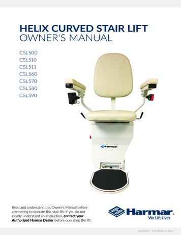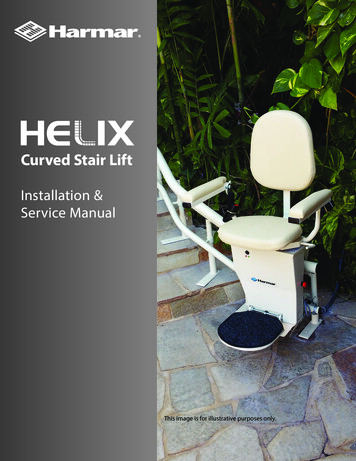
Transcription
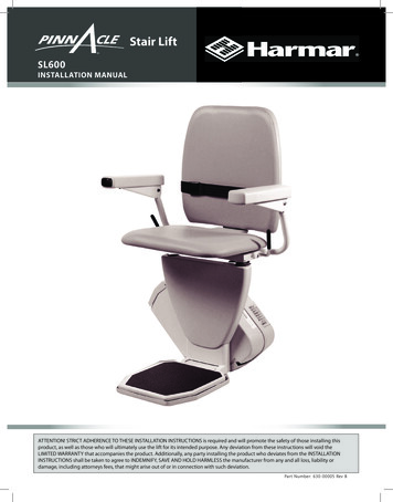
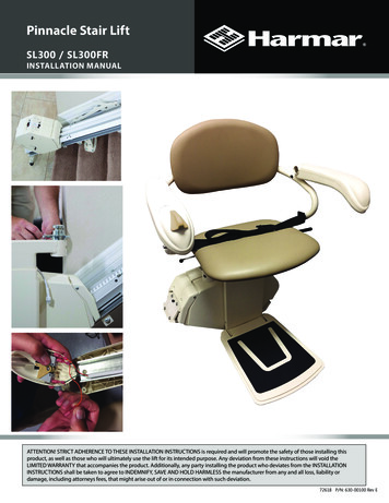
Pinnacle Stair LiftSL300 / SL300FRINSTALLATION MANUALATTENTION! STRICT ADHERENCE TO THESE INSTALLATION INSTRUCTIONS is required and will promote the safety of those installing thisproduct, as well as those who will ultimately use the lift for its intended purpose. Any deviation from these instructions will void theLIMITED WARRANTY that accompanies the product. Additionally, any party installing the product who deviates from the INSTALLATIONINSTRUCTIONS shall be taken to agree to INDEMNIFY, SAVE AND HOLD HARMLESS the manufacturer from any and all loss, liability ordamage, including attorneys fees, that might arise out of or in connection with such deviation.72618 P/N: 630-00100 Rev E
Pinnacle SL300CONTENTSContentsPRELIMINARY CHECKS3Tools Required . . . . . . . . . . . . . . . . . . . . . . . . . . . . . . . . 3Included Parts . . . . . . . . . . . . . . . . . . . . . . . . . . . . . . . . . 3INSTALLATION PROCEDURES4-12Determine Rail Length. . . . . . . . . . . . . . . . . . . . . . . . . 4Rail Installation . . . . . . . . . . . . . . . . . . . . . . . . . . . . . . 5-6Chassis Installation. . . . . . . . . . . . . . . . . . . . . . . . . . . . . 7Final Rail Installation. . . . . . . . . . . . . . . . . . . . . . . . . 8-9Footrest and Seat Installation. . . . . . . . . . . . . . 10-11Procedure to Switch Armrest Control . . . . . . . . . 11Audible Tones. . . . . . . . . . . . . . . . . . . . . . . . . . . . . . . . 12Major Fault Tones. . . . . . . . . . . . . . . . . . . . . . . . . . . . 12REMOTE CONTROL OPERATIONAny alterations to the equipment without writtenauthorization by the manufacturer may voidthe warranty.Harmar lifts are designed to be installed with aslittle assembly by the installer as possible. If youhave questions, concerns or comments related toinstallation, please contact Harmar’s Technical ServiceDepartment.SYMBOLS USED IN THIS MANUALREAD MANUAL - Pay close attention tothe instructions in the manual.13Remote Control Operation. . . . . . . . . . . . . . . . . . . 13Remote Control Reprogramming. . . . . . . . . . . . . 13COMPLETION PROCEDURESRead and understand this manual prior toattempting stair lift installations. Please referto the Owner’s Manual for Limited Warrantyinformation and operating instructions. The Owner’sManual must be reviewed with and given to the ownerof the lift before it is put into service.14-15Test Armrest Control Switch. . . . . . . . . . . . . . . . . . 14Tighten Brackets. . . . . . . . . . . . . . . . . . . . . . . . . . . . . 14Set Upper and Lower Travel Limits. . . . . . . . . . . . 14Test Safety Stop Switches. . . . . . . . . . . . . . . . . . 14-15CAUTION - Hazardous situation. If notavoided, could result in serious damageto property.WARNING - Hazardous situation. If notavoided, could result in serious injury toinstaller or user.TIP - Helpful tips that will facilitate easeof installation.Additional System Checks. . . . . . . . . . . . . . . . . . . . 15FOLDING RAIL INSTALLATIONTECHNICAL SPECIFICATIONS20END-USER FAMILIARIZATION21NOTES216-19INDICATIONS OF USE STATEMENTThe Pinnacle SL300 Series is to assist transfer ofpatients or mobility impaired persons, up and downbetween levels of a residential home.22-23 www.harmar.com 2018Harmar Mobility, LLC All Rights Reserved
PRELIMINARY CHECKSPinnacle SL300Rail Box:Bottom rail pre-installed with:Bottom end plateCharge strip wire harnessBottom limit camTools RequiredThe following is a suggested list of basic tools tohave on hand during installation.Cordless drillAllen wrenches (5/64", 5/32", 3/16", 5/16")Phillips screwdriver (#3)Nut driver (3/8" and 5/16")6-10" driver extensionT30 Torx bit (included)LevelHack saw or chop sawSAE socket setSAE wrenchesTape measureVolt MeterIncluded PartsBefore beginning installation, please inspect andcheck the box contents. Report any damage to yourdealer.Chassis Box:ChassisIn Tray2 Wireless call/send hand controlsPower supply with power cordManual overide toolInstallation ManualOwner’s ManualWarranty Registration form72618 P/N: 630-00100 Rev EJoint pins and joint brackets(two-piece rail only)Plastic gear rackTop rail pre-installed with:Charge strip wire harnessRail accessories (plastic bag):Top end plateCompression bolts (2 sizes)Self-cutting screws (1/4"-20 X 1")Torx T30 driver bitRail Bracket Box:Rail brackets (2, 3, 4, or 6 per set)Wood screws (#14 X 2" (4 per rail bracket)Chair and Footrest Box:Chair with seat beltFootrestSeat swivel post with fastenersRetractable seat belt (optional)Rail Parts (plastic bag):Extra plastic racks (2 or 3)Top limit camSL300 Pinnacle Stair Lift Installation Manual3
Pinnacle SL300INSTALLATION PROCEDURESA. DETERMINE OVERALL RAIL LENGTH(Only if rail did not come pre-cut to length)1. Determine any obstructions that will affect theposition and length of the rail. These may includewalls, doors, hallway orientation, etc.2. Measure the overall length of the stairs from thenose at the top landing of the stairs to the floor atthe bottom (nose to floor measurement, (128").[Figure 4-1]3. For a normal stairway with adequate space for alanding, add 13" to the nose to floor measurement.This will provide enough rail length to allowthe stair lift to be adjusted so that the floor-toseat height will be the same at both the top andbottom (e.g., 141").Figure 4-14. If the top landing has restrictions (i.e., a wall ordoorway), use the chart below to determine thelength of extension that should be used.5. To cut the rail, use a standard 12" chop saw,with a blade designed to cut aluminum.TIPDo not cut rail inside the house (aluminumchips are very hard to remove from carpets)Extension7 in3.9 in9 in5 in11 in6.1 in13 in7.2 inHorizontal intrusion on top landingDO NOT cut the end of the rail that contains the joint holes.TIPRemove the charger strips and wire harness before cutting.Installation Site Electrical Requirements - The lift shall be connected to a dedicated120V 15A electrical circuit.4 www.harmar.com 2018Harmar Mobility, LLC All Rights Reserved
INSTALLATION PROCEDURESPinnacle SL300B. RAIL INSTALLATION1. Open the rail box and remove the contents.2. Position the bottom rail (the rail with end plateattached) directly on the stairs with the end platetowards the bottom of the stairs and the plasticrack facing up. Place an object that measures 1/2"between end plate and the floor. [Figure 5-1 and 5-2]Figure 5-1TIPFigure 5-2Use the chair box, or another heavy object, like a toolbox, atthe bottom to prevent the rail from sliding down the stairs.3. Position the two ends of the rail close together.Locate and connect the plug on the ends of the twopower harnesses inside the two rail pieces. [Figure 5-3]4. With the plastic rack facing up, slide the toprail into the bottom rail and guide them togetherusing the pre-installed pins. Gently tap the top railif necessary to get them close together. Be cautiousnot to pinch the power harness. [Figure 5-4]5. Install two (2) joint fasteners and firmly tightenwith 3/16" Allen wrench. Then slide rack piecesdown to cover joint. [Figure5-5]Figure 5-3Figure 5-4Figure 5-5Figure 5-66. Turn over joined rails and install the remainingtwo (2) joint fasteners and firmly tighten with 3/16"Allen wrench. [Figure 5-6]7. Install rail brackets with label facing the wall byloosening the screws and snapping each bracketedge into the slot, or slide the brackets on from thetop of the rail. [Figure 5-7]Figure 5-7TIPThe brackets are tightened from one side only. It is importantthat the bracket be installed with the nut side facing the wallso when the rail is turned over to its correct orientation thescrews will be accessible.72618 P/N: 630-00100 Rev ESL300 Pinnacle Stair Lift Installation Manual5
Pinnacle SL300INSTALLATION PROCEDURES8.A. For double rails, the first rail bracket shouldbe tightened in place so when turned overthe back of the bracket touches the rear ofthe first step from the bottom landing. Thesecond and third brackets should be placedand tightened on the steps on each sideof the rail joint, again so the back of thebracket touches the rear of the step. Thefourth and final bracket should be placedon the last step before the top landing,again tightening it so it touches the front ofthe rear of the last step.B. Tighten the first rail bracket in place sowhen turned over the back of the brackettouches the rear of the first step from thebottom landing. Place the other rail onthe last step before the top landing, againtightening it so it touches the rear of thelast step.Figure 6-19. Turn the rail right side up (plastic side facing up).[Figure 6-1]10. Measure any obstruction from the wall (thismay include handrails, molding, light switches,etc.) and adjust the edge of the brackets an equaldistance from the wall. The minimum distance willbe 1.0" from the wall or any obstruction.Figure 6-211. The underside of the rail must be at least 3"above the stair tread nose to provide clearancefor the footrest. To achieve this 3" clearance movethe rail and bracket forward. Once the clearance is3", tighten all bracket nuts to hold the brackets inposition. To maintain the 3" clearance, and to holdthe rail in place, secure the bottom bracket to thefirst step from the floor with 3" wood screws, usinga 3/8" nut driver on a 6-10" extension of a cordlessdrill. [Figure 6-2 and 6-3]Figure 6-36 www.harmar.com 2018Harmar Mobility, LLC All Rights Reserved
INSTALLATION PROCEDURESPinnacle SL300C. CHASSIS INSTALLATION1. Remove chassis from box. Lift the chassis withthe manual override hole (on bottom) facing thedownhill side of the stairs and gently slide thechassis onto the rail until it makes contact with theplastic rack. DO NOT LET THE CHASSIS FREE FALLDOWN THE RAIL. [Figure 7-1]WARNINGBe careful not to trap fingersbetween the rail and the chassis.2. Use the installation switch (the black switch onthe top of the chassis) to move the chassis at least24" down the rail, pushing gently on the chassis toensure the chassis does not pull any rack to the top.[Figure 7-2]Figure 7-13. Loosen, but do not remove, the four (4) seatleveling bolts two (2) on each side of the chassis)and then align them vertically using a level. Firmlytighten the two (2) bolts on the side of the chassisfacing the wall. [Figure 7-3]Figure 7-2Installation SwitchWARNINGDo not ride on the chassis or lift untilthe install is complete.Figure 7-32 bolts on either side of chassis72618 P/N: 630-00100 Rev ESL300 Pinnacle Stair Lift Installation Manual7
Pinnacle SL300INSTALLATION PROCEDURESD. FINAL RAIL INSTALLATION1. Install the remaining plastic rack pieces in theupper rail. [Figure 8-1]2. Use a hacksaw or chop saw to cut the last plasticrack piece flush with the rail end. Place somethingon the floor to catch debris or mark and cut therack outside. [Figure 8-2]The exposed, cut end of the plastic rack should befacing the top end of the rail (the factory-cut sideshould butt against the lower rack).Figure 8-13. Slide the top limit cam into one of the cam slots(it doesn’t matter which side), and tighten thepre-inserted Allen screw with a 5/64" Allen wrench.This will be used to set the final upper limits for thestair lift [Figure 8-3].4. Remove charging strip from the rail box.Connect charging strip connector to the powerwire that runs through the center of the rail fromthe lower charging strips. [Figure 8-4]Figure 8-2Insert the two (2) charger strips into the keyed slotsat the top of the rail (while standing on the toplanding looking down). The charging strip with thered wire should be inserted into the left slot withthe metal strip facing out. The charging strip withthe black wire should be inserted into the right slotwith the metal strip pointing out. [Figure 8-4]Bend the red and black wire tabs in toward thecenter of the track.Figure 8-3Insert excess cable into the rail, leaving the pigtailwith the Molex connector on the outside.Figure 8-48 www.harmar.com 2018Harmar Mobility, LLC All Rights Reserved
INSTALLATION PROCEDURESPinnacle SL3005. Install the end plate to the top of the track withthe four (4) self-cutting Torx screws using thesupplied T30 Torx bit. [Figure 9-1]TIPToo much torque applied to these screwsmay result in damage. Take your time andapply grease to threads.6. Install one of the rack pre-compression screwsin the threaded hole in the top plate of the rail, andtighten it as firmly as possible by hand with a 5/32"Allen wrench. [Figure 9-2]Figure 9-1There are two (2) kinds of pre-compression screws: 3/4" for rails under 12 ft 1" for rails over 12 ft7. Plug in the power supply at either end of therail, depending on the closest or most convenientlocation of a wall power supply. Minimize wire lengthand intrusion. [Figure 9-3 & 9-4]WARNINGFigure 9-2Use care in routing the charger lead.If possible, secure along or inside wallto avoid creation of a tripping hazard.Figure 9-3Figure 9-472618 P/N: 630-00100 Rev ESL300 Pinnacle Stair Lift Installation Manual9
Pinnacle SL300INSTALLATION PROCEDURESE. FOOTREST & SEAT INSTALLATION1. Use the installation switch to drive the chassisdown to the bottom step. This will provide a safearea to install and adjust the footrest. DO NOT drivethe unit into bottom stop.2. Turn the red “ON/OFF” switch located on the topof the chassis to the “OFF” position (0).3. Remove the four (4) screws holding the verticalseat support shroud in place with a Phillips screwdriver (#3) and set aside.4. Position the footrest onto the two (2) seatleveling bolts on the outside of the chassis byaligning the large opening at the slot ends of thefootrest. [Figure 10-1]Figure 10-2Figure 10-1If the wrong set of connectors are used, the unit willwork backwards.TIP5. Ensure the footrest is fully engaged. Use a levelto level seat and then tighten the 4 bolts on thefront and back of the chassis.[Figure 10-2]Figure 10-3Orientation of seat posts left or right.6. If the seat swivel post is not already installedon the seat base hole closest to the top of thestairs remove the two (2) screws on the sides ofthe supporting using a 5/32" Allen wrench andreinstall on the proper side [oriented like Figure10-3]. Be sure to securely tighten the two (2) bolts[Figure 10-4].7. Replace the vertical seat support shroud andsecure to vertical seat support with four (4) screwsthat were removed in step 3.Figure 10-4TIP10 www.harmar.comWhen the 6-pin footrest and/or the 8-pin chaircables are connected to the chassis, the blackinstallation switch on the chassis is disabledand will not function. 2018Harmar Mobility, LLC All Rights Reserved
INSTALLATION PROCEDURESPinnacle SL3008. Position the seat directly aligned over the carriageand place onto the seat swivel post. Depressthe swivel lever until the seat is fully engagedwith the swivel post. Check the swivel lever totest the locking mechanism. THE SYSTEM WILLNOT FUNCTION IF PROPER ENGAGEMENT IS NOTACHIEVED. [Figure 11-1]9. Connect the seat cable to the 8-pin connector onthe chassis that is opposite the foot plate & closestto the wall.Figure 11-1Insert 6-pin footrest cable into connector that isadjacent to the 8-pin cable. [Figure 11-2]F. PROCEDURE TO SWITCH ARMRESTCONTROL FROM RIGHT TO LEFT HAND1. Turn the unit off2. Remove the integrated paddle switch / palm restby removing screw underneath the arm [Figure 113].Figure 11-23. Disconnect the wires from the switch[Figure 11-4] and then cut off the connectors andremove seatbelt bolts in order to re-rout harness.[Figure 11-5]4. Remove upper half of both armrests.5. Reroute the harness to the other armrest.[Figure 11-6]6. Re-terminate the wires and connect the switch.7. Reassemble arms and reinstall seatbelt.Figure 11-3Figure 11-572618 P/N: 630-00100 Rev EFigure 11-4Figure 11-6SL300 Pinnacle Stair Lift Installation Manual11
Pinnacle SL300INSTALLATION PROCEDURESH. TONES INFORMATIONMinor faultsG. AUDIBLE TONESSingle long beep (will reset once fault is cleared)If the lift does not operate, check the safety senors: Seat swiveled out of position Edge safety detected Current overload condition A Low battery voltage condition Seat swivel sensor (seat should be in thelocked position) Footrest lower sensor (check by pushing inon the safety pan on the footrest) Upper foot pan safety sensor (check bypushing on the safety pan on the footrest). On folding rail model only-Uphill safetysensor (ensure nothing is blocking upwardpassage) On folding rail model only-Downhillsafety sensor (ensure nothing is blockingdownward passage)Pulsing BeepLift stopped off of charge strip. Will sound after30 second for 30 seconds. It will repeat ever 10minutes until lift is operated or returned to chargestrips.If the stairlift still does not operate after testingsensors, turn the unit off and re-check all wireMajor TonesTonesNumber of Beeps.Runaway1No Power2Conflicting Switches Footrest UP & Footrest DOWN3*Conflicting Switches Obstruction UP & Obstruction DOWN4*Conflicting Switches Footrest DOWN & Obstruction UP5Conflicting Switches Footrest UP & Obstruction DOWN6Conflicting Switches STOP UP & STOP DOWN switches both Detected7Conflicting Switches STOP UP & STOP DOWN switches both NOT Detected8* If configured for your model.12 www.harmar.com 2018Harmar Mobility, LLC All Rights Reserved
REMOTE CONTROL OPERATIONPinnacle SL300Remote Call/Send Control OperationA. REMOTE CONTROL OPERATIONB. REMOTE CONTROL RE-PROGRAMMING1. Press and hold theappropriate directionalbutton on the front of thehand control.All call/send controls are factory programmed.Re-programming is not normally necessary duringinstallation.The chair lift will operatewith or without a rider. Allsafety sensors on the chairlift are designed to continueto operate in their normalmode.2. If the chair lift fails to respond, this may indicatethe batteries are discharged and need to bereplaced. Remove the back cover of the control andreplace with commonly available AAA batteries,ensuring that the polarity is correct.In the event that the remote call/send control needsto be re-programmed, it is essential to programBOTH controls in one programming cycle. Do so bycompleting the following:1. Start with the red “ON/OFF” switch in the “OFF”position (0).2. Disconnect the 6-pin jumper and 8-pin chair wireharnesses from the chassis.3. Press and hold the install switch (located on thetop of the chassis) in either direction.4. Turn the red “ON/OFF” switch to the “ON” position(I). Wait for circuit board to beep and then releasethe install switch.5. The lift will begin to beep rapidly (this means thefirst remote control is ready to program).6. Press and release the “UP” or “DOWN” button ofthe first remote control (the first remote control isnow programmed).7. Press and release the “UP” or “DOWN” buttonof the second remote control (the second remotecontrol is now programmed).8. Upon completion, two beeps will indicate thatboth remote controls have been programmed.9. Turn the “ON/OFF” switch to the “OFF” position (0).10. Connect the 6-pin jumper and 8-pin chair wireharnesses to the chassis and then turn the red “ON/OFF” switch to the “ON” position (I).11. Test each remote control in both the up anddown directions.72618 P/N: 630-00100 Rev ESL300 Pinnacle Stair Lift Installation Manual13
Pinnacle SL300COMPLETION PROCEDURESCompletion ProceduresA. TEST ARMREST CONTROL SWITCH1. Ensure that the unit travels correctly byoperating the armrest control switch whilestanding in front of the unit.2. Depress the switch in the upstairs direction tomove up. The lift will begin to smoothly accelerateupwards. The lift will continue to move upwards aslong as the switch is depressed.3. Release the switch and the lift will come to animmediate stop.4. Depress the switch in the downstairs directionto move down. The lift will begin to smoothlyaccelerate downwards.5. Release the switch and the lift will come to animmediate stop.6. Run the chair all the way up and down therail to ensure that the top of the seat back has atleast a 1/2" in clearance from the wall and anyobstructions.WARNINGDo not ride on the chassis or liftuntil the install is complete.B. TIGHTEN BRACKETS1. Install and fully tighten the rail bracketmounting screws (four (4) screws per bracket). Forhardwood stairs, a pilot hole should be drilled first.For plywood or particle board stairs care must betaken to prevent stripping.C. SET UPPER AND LOWER TRAVEL LIMITS1. Test the lower travel limit by operating the liftdownward, keeping the switch depressed. The unitshould begin to decelerate about 3 in from its finalresting position and stop clear of the floor.14 www.harmar.com2. The final stopped position can be adjustedto accommodate the height of the user byrepositioning the limit cam located in a slot in the rail.3. Use a 5/64" Allen wrench to loosen the set screwin the limit cam. Adjust the limit cam up or down andretighten the set screws. Repeat the above steps untilthe lift stops in the desired position.4. Repeat the above steps to set the upper limits.For safety, the footrest should be set at least levelwith the upper landing.5. The optimum position is met when the seatheight above the floor is the same at the top andbottom of the stairs.D. TEST SAFETY STOP SWITCHES1. On the folding rail model only (Unless orderedas an upgrade) - Safety stop switches are locatedin both the upward and downward ends of thechassis providing protection from obstructions onthe rail.2. Safety stop is located in the footrest providingprotection from obstructions and trapping hazardson the stairs.3. A safety stop switch is part of the swivel seatmechanism and prevents the lift from operatingwhen the swivel is in use.4. Test all the safety stop switches by driving thelift down and touching the downward end of thechassis (this is for the folding rail model only),the lower edge of the footrest, and the undersideof the footrest in both its folded and unfoldedpositions.5. In each of the above cases the unit shouldcome to an immediate halt and should beepintermittently.6. When the control switch is released, the unitshould NOT be able to be driven in the directionthat the lift initially engaged the obstacle. Test thiscondition. 2018Harmar Mobility, LLC All Rights Reserved
COMPLETION PROCEDURESPinnacle SL3007. Repeat the above tests while driving the lift inopposite direction.8. If any safety condition does not function properly,carefully review all installation instructions, reset the“ON /OFF” switch. Repeat the above tests.9. If any safety stop switch fails to immediatelystop the lift, immediately call the manufacturer forassistance in diagnosing and repairing the problem.DO NOT USE THE LIFT.E. ADDITIONAL SYSTEM CHECKS1. After the successful testing of all safety switches,sit on the lift and operate to the top of the stairs.Keeping the control switch depressed continuously,the lift should gently decelerate and then stop atthe top of the rail.2. As a final adjustment, sit on the lift and do two(2) complete up trips and stop with the chair atthe bottom. Then tighten the compression screwin the top end plate, then run the chair to the topand again tighten the compression screw. Run thechair to the middle and do a final tightening of thecompression screw.3. Drive the lift to the bottom, keeping the controlswitch depressed all the time, and check that the liftgently decelerates and stops so the footrest pan isclear of the floor. If necessary adjust the limit camswith a 5/64" Allen wrench.4. Move the lift about 3 ft from either the topor bottom of the rail. After 30 seconds the beepindicating that the lift is not positioned on a chargepoint. The beep will stop after 30 seconds .5. Test the seat swivel at the top by using the leversand swiveling the seat towards the landing andstop the seat at 35 and 85 degrees. The seat swivellevers will release into a locked position at each ofthese angles. The lift will not operate in any of thesepositions if the control switch is depressed. Returnthe seat to its normal position and the lift will nowoperate normally.72618 P/N: 630-00100 Rev ESL300 Pinnacle Stair Lift Installation Manual15
Pinnacle SL300FOLDING RAIL INSTALLATIONFolding Rail InstallationNote - The photos in this section show a "left" folding rail, assembled to be installed on the left side ofthe stairway. If you’re assembling a "right’"side, please complete all of these steps in mirror-image towhat’s shown.As always, if you encounter any difficulty, please call Harmar Technical Support at: (866) 351-2776FOLDING RAIL INSTALLATION PROCEDURES1. Orient the two rail brackets onto the folding railas shown [Figure 16-1], with the nuts on the sameside as the folding mechanism (for either left orright folding). [Figure 16-2]2. Expand and snap the two brackets over the rail,so the top is in the bracket-groove. [Figure 16-3]Figure 16-13. Partially tighten the two nuts that positionthese on the rail, using a 1/2" wrench (deep socketpreferred), so they won’t slide when you’re testfitting the position. [Figure 16-4]Figure 16-2Figure 16-3Figure 16-416 www.harmar.com 2018Harmar Mobility, LLC All Rights Reserved
FOLDING RAIL INSTALLATIONPinnacle SL3004. Place the rail onto the stairway with the bottombracket on the second step, as shown. Note that thebottom feet should approximately rest on the floorwith the rail straight, but they will be adjusted later.[Figure 17-1]5. Measure to verify that the underside of the railis more than 3" from the stair noses, both at thesecond step bracket and at the upper bracket. If not,reposition the brackets as needed. This clearanceis required for the stair lift footrest. In someinstallations, you may not be able to get 3" or morewith the standard stair-bracket. Contact Harmar toget tall brackets. [Figure 17-2 & 17-3]6. Measure from the side of the rail to the wall. Theminimum clearance that will work with a foldingstair lift rail is 3". Set the folding section of the stairlift rails to a distance of 3" from the wall or more.This will leave about 1/2" of clearance at the ball ofthe gas-spring. [Figure 17-4]Figure 17-1Bottom bracket3" or moreFigure 17-2Upper bracket3" or moreFigure 17-3Figure 17-472618 P/N: 630-00100 Rev ESL300 Pinnacle Stair Lift Installation Manual17
Pinnacle SL300FOLDING RAIL INSTALLATION7. Fasten down the near corner of the lowerbracket using a drill that has extensions at least10" long and a 3/8" socket. [Figure 18-1 & 18-2]8. Measure from the side of the rail at the upperbracket of the folding rail.Set this at 3" or more. Screw down one corner ofthe bracket.9. Join to upper rail, following regular procedures(this procedure is detailed on page 5). Thisprocedure includes plugging the battery chargingwire harness for the folding rail into the chargingharness from the upper rail. The power supplyitself can be plugged into either the top rail (forthe top of the stairs), or to the charge plug fromthe folding rail, which comes out just higher thanthe folding mechanism for the bottom of thestairway.Figure 18-1Figure 18-210. Fasten down the other screws of both railbrackets using the power drill and long extensionwith the 3/8" socket. [Figure 18-3]11. Adjust the height of the two feet using a 9/16"open end wrench. Set them so that both rest onthe floor with the rail fully straight. The foot fartherfrom the wall should be set a little taller than theinside one to get it to seat flat on the floor, sincethe Pinnacle rail brackets intentionally lean the railtoward the wall just a little. [Figure 18-4]Figure 18-3Figure 18-418 www.harmar.com 2018Harmar Mobility, LLC All Rights Reserved
FOLDING RAIL INSTALLATIONPinnacle SL30012. Reinstall the two plastic caps on the feet tocover the threads [Figure 19-1]13. Carefully move the fork with your hand to makesure it operates smoothly. Allow it to go all the way tothe floor. Confirm that both feet sit level on the floorand the hinge-joint is fully straight. [Figure 19-2]14. Follow the normal procedure for installing railWARNINGBe careful not to pinch your fingerswhen moving the fork.brackets and tightening them. This procedure isdetailed on pages 5 & 6 (steps 7 & 8).Figure 19-115. Test ride the unit a couple of times to verify thatthe folding rail is operating properly.Figure 19-272618 P/N: 630-00100 Rev ESL300 Pinnacle Stair Lift Installation Manual19
Pinnacle STechnical SpecificationsWeight Capacity300 lbTrack (Rail) TypeAluminum ExtrusionTravel15'6" standard - 32' maxAvg. # of Return Trips per Charge40Minimum Folded Width11.0" / 13.0" Folding RailMinimum Footrest Height2.5"Clear Distance Between Armrests20"Floor to Seat Height20"Minimum Wall to Side of Rail6"Seat Base15" Deep, 18" WideSeatback9.5" Tall, 16" WideFootrest Size12.5" Wide, 15" LongElectrical Requirements120 / 240 VACBatteries2 12v; 7.2amp hr.Drive SystemNylon Polymer Worn GearSafety StandardsComplies with ASME A18.1 & ASME A17.5Warranty2 Year Parts / 10 Year Gear Rack / 1 Year BatteriesCM314812520 www.harmar.com 2018Harmar Mobility, LLC All Rights Reserved
TECHNICALFOLDING SPECIFICATIONSRAIL INSTALLATIONPinnacle SL300FAMILIARIZATIONIt is very important to familiarize the customerwith the stairlift as the final step in installation.To acheive this, walk the customer through theOwner's Manual.1. Present the unit from seat, controls, footrest,track, on / off switch, call / sends, and power supply.2. Demonstrate how to properly enter and exit theseat.a. At bottom with seatbeltb. At top, swiveled away from staircase, withseat beltc. If transferring, raise one armrestd. Always use seat belt3. Show how arm controls work.4. Show how obstruction sensors work and howrelieved.5. Show how call / sends work - line of sight.6. Show how seat swivel interlock works.7. Review beep codes.8. Fold up unit when not in use.9. Power management if not used for long duration.a. Dynamic for charging on charge stripb. Light on charger color codes10. Battery replacement and service.11. Warranty registration72618 P/N: 630-00100 Rev ESL300 Pinnacle
SL300 Pinnacle Stair Lift Installation Manual 5 INSTALLATION PROCEDURES Pinnacle SL300 B. RAIL INSTALLATION 1. Open the rail box and remove the contents. 2. Position the bottom rail (the rail with end plate attached) directly on the stairs with the end plate towards the bottom of the stairs and the plastic rack facing up.