Transcription
SSE-F3548S/SSE-F3548SRLink AggregationUser’s GuideRevision 1.0
The information in this USER’S GUIDE has been carefully reviewed and is believed to be accurate. Thevendor assumes no responsibility for any inaccuracies that may be contained in this document, makesno commitment to update or to keep current the information in this manual, or to notify any personorganization of the updates. Please Note: For the most up-to-date version of this manual, please see ourweb site at www.supermicro.com.Super Micro Computer, Inc. (“Supermicro”) reserves the right to make changes to the product describedin this manual at any time and without notice. This product, including software, if any, anddocumentation may not, in whole or in part, be copied, photocopied, reproduced, translated or reducedto any medium or machine without prior written consent.DISCLAIMER OF WARRANTY ON SOFTWARE AND MATERIALS. You expressly acknowledge and agree thatuse of the Software and Materials is at your sole risk. FURTHERMORE, SUPER MICRO COMPUTER INC.DOES NOT WARRANT OR MAKE ANY REPRESENTATIONS REGARDING THE USE OR THE RESULTS OF THEUSE OF THE SOFTWARE OR MATERIALS IN TERMS OF THEIR CORRECTNESS, ACCURACY, RELIABILITY, OROTHERWISE. NO ORAL OR WRITTEN INFORMATION OR ADVICE GIVEN BY SUPER MICRO COMPUTER INC.OR SUPER MICRO COMPUTER INC. AUTHORIZED REPRESENTATIVE SHALL CREATE A WARRANTY OR INANY WAY INCREASE THE SCOPE OF THIS WARRANTY. SHOULD THE SOFTWARE AND/OR MATERIALSPROVE DEFECTIVE, YOU (AND NOT SUPER MICRO COMPUTER INC. OR A SUPER MICRO COMPUTER INC.AUTHORIZED REPRESENTATIVE) ASSUME THE ENTIRE COST OF ALL NECESSARY SERVICE, REPAIR, ORCORRECTION.LIMITATION OF LIABILITY. UNDER NO CIRCUMSTANCES INCLUDING NEGLIGENCE, SHALL SUPER MICROCOMPUTER INC. BE LIABLE FOR ANY INCIDENTAL, SPECIAL, OR CONSEQUENTIAL DAMAGES THAT RESULTFROM THE USE OR INABILITY TO USE THE SOFTWARE OR MATERIALS, EVEN IF SUPER MICRO COMPUTERINC. OR A SUPER MICRO COMPUTER INC. AUTHORIZED REPRESENTATIVE HAS BEEN ADVISED OF THEPOSSIBILITY OF SUCH DAMAGES.Any disputes arising between manufacturer and customer shall be governed by the laws of Santa ClaraCounty in the State of California, USA. The State of California, County of Santa Clara shall be theexclusive venue for the resolution of any such disputes. Super Micro's total liability for all claims will notexceed the price paid for the hardware product.Manual Revision 1.0Release Date: 3/2/2020Unless you request and receive written permission from Super Micro Computer, Inc., you may not copy any part ofthis document.Information in this document is subject to change without notice. Other products and companies referred to hereinare trademarks or registered trademarks of their respective companies or mark holders.Copyright 2020 by Super Micro Computer, Inc.All rights reserved.Printed in the United States of AmericaSupermicro SSE-F3548S/SSE-F3548SR Link Aggregation User’s Guide2
Document Revision HistoryDateRevision03/2/20201.0DescriptionInitial document.Supermicro SSE-F3548S/SSE-F3548SR Link Aggregation User’s Guide3
Contents1Introduction . 52Link Aggregation Support . 53Link Aggregation Numbers . 64Link Aggregation Defaults . 65Static Link Aggregation. 66Dynamic Link Aggregation - LACP . 77Link Aggregation Port Channel . 87.1Creating Port Channels . 87.1.1Creating Port Channel Interfaces . 87.1.27.2Adding Member Ports to Port Channels . 9Modifying Port Channels . 117.2.1Modifying Port Channel Parameters . 117.2.2Modifying Port Channel Member Ports . 127.2.3Adding New Member Ports . 127.2.47.3Removing Member Ports . 12Removing Port Channels . 157.4LACP Parameters. 167.4.1LACP System Priority . 167.4.2LACP Port Priority. 177.4.3LACP Timeout . 187.4.47.5LACP Wait Time . 21Load Balancing . 227.6Link Aggregation Configuration Example. 24Contacting Supermicro. 30Supermicro SSE-F3548S/SSE-F3548SR Link Aggregation User’s Guide4
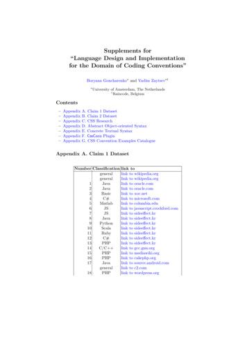
1 Introduction The Link Aggregation feature connects two or more physical links between two network devices withoutforming loops. Link aggregation can be used between switches, servers and routers.Link aggregation provides the following advantages:Increased bandwidth – User can connect up to eight physical links between devices to increase the linkbandwidth. When 25 Gbps links are aggregated, users can get an aggregated link with up to 200 Gbpsbandwidth. When ports are set to 10Gig speed, users can aggregate eight 10Gig ports to get anaggregated uplink with up to 80 Gbps.Incremental bandwidth – Users can start aggregation with a fewer number of ports and then increasethe number of ports in aggregation (up to eight) incrementally based on the bandwidth requirements.Redundancy - When one of the physical links fails, traffic will be distributed over the other remaininglinks in the aggregation.Figure LA-1: Link AggregationSwitch ACx 0/3Fx 0/1Cx 0/4Fx 0/2Switch BPort channel 1 between switchesPort channel 2between serverand switchThe “port channel”, “channel group” and “ether channels” are used synonymously to refertoaggregate links2 Link Aggregation SupportSupermicro switches support both static and dynamic link aggregations. Dynamic link aggregationsupport is based on the Link Aggregation Control Protocol (LACP).Supermicro SSE-F3548S/SSE-F3548SR Link Aggregation User’s Guide5
Supermicro switches support only Layer 2 level link aggregation. Hence, only switching ports can beaggregated.Supermicro switches do support the Multiple Chassis Link Aggregation (MLAG) feature.3 Link Aggregation NumbersSupermicro switches support up to 52 port channels.Each port channel can have eight active links.Users can configure more than eight ports to a LACP mode port channel. However, amaximum of eight ports only can be in an active bundle state in any port channel.4 Link Aggregation DefaultsThe Link Aggregation feature is enabled by default in Supermicro switches.When a port channel interface is created, it will be added to VLAN 1 by default.Port channels use the MAC address of the first physical link added to it.The default LACP system priority is 32768.The default LACP port priority is 128.The default LACP timeout is long (30 seconds).The default LACP wait time is 2 seconds.5 Static Link AggregationSupermicro switches support static link aggregation.User can add up to eight ports to a static port channel group. When the physical link status of one ormore ports in a channel group is up, that port channel status will be up. The port channel status will bedown when the ports physical link status of all members are down.Switches do not exchange any port channel control information with other end devices in static linkaggregation. Hence, users need to configure the port channel groups and member ports correctly onboth end devices.Supermicro SSE-F3548S/SSE-F3548SR Link Aggregation User’s Guide6
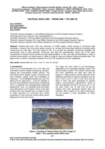
6 Dynamic Link Aggregation – LACPSupermicro switches support dynamic link aggregation through IEEE 802.3ad Link Aggregation ControlProtocol (LACP).Users can add one or more ports to an LACP mode port channel. When more than eight member portsare configured, only the first eight member ports reaching the “bundle” state will be used for datatraffic.Ports in LACP mode exchange LACP packets with other end devices. The LACP system priority, switchMAC address, port LACP priority, port number and aggregation key are all exchanged betweendevices. Based on the exchanged information, both end devices agree on the status of the memberports. The member ports that successfully negotiated LACP parameters will be moved to the “bundle”state. The member ports that could not reach agreement on LACP parameters will stay in the“independent” state. Switches do not send traffic on member ports in “independent” state.When one or more member ports reach the “bundle” state, the port channel status will be up. Theport channel status will be down when all its member ports are either physically down or in the“independent” state.Ports can be configured in either active or passive LACP mode. Ports in active LACP mode will initiateLACP negotiation by sending LACP messages to the other end devices. Ports in passive LACP mode willnot initiate the LACP negotiation, but they will respond to LACP messages if received from other end.Users should configure for an active LACP mode on at least one end of the LACP portchannel connection. If LACP mode is configured as passive on both end devices, the portchannel interface will not come up. Configuring LACP mode as active on both the enddevices is allowed.Figure LA-2: Dynamic Link AggregationFigure LA-2: Dynamic Link AggregationSupermicro SSE-F3548S/SSE-F3548SR Link Aggregation User’s Guide7
The figure above shows an example of a port channel configuration with port status and aggregatedports. In this example, port 5 is not configured on LACP mode on switch B, and is therefore shown asbeing in the “independent” state and not part of the aggregated ports.7 Link Aggregation Port Channel7.1 Creating Port ChannelsPort channel creation involves two steps: the first is to create the port channel interfaces and thesecond is to add member ports to the port channel interfaces.7.1.1 Creating Port Channel InterfacesFollow the steps below to create port channel interfaces in Supermicro switches.StepCommandDescriptionStep 1configure terminalEnters the configuration modeStep 2interface port-channel channel-group-number Orno interface range port-channel channel-groupnumber .Creates a port channel using “interfaceport—channel” command.channel-group-number – may be anynumber from 1 to 65535.To configure multiple port channelinterfaces, use the “interface range ”command. To provide a range, use ahyphen (-) between the start and endinterface numbers.E.g.: int range po 1-3To provide multiple interfaces orranges, separate with a comma (,).E.g. : int range po 1, 2Step 3description string Optional step - adds any name string tothe port channel interfaces using thedescription command.The string may be up to 64 charactersin length.The port channel description strings willnot affect the member portsSupermicro SSE-F3548S/SSE-F3548SR Link Aggregation User’s Guide8
description strings configurations.Step 4mtu framesize Optional step.Configures the MTU for the portchannel interfaces.framesize may be any number fromPort channel MTU will be used on its allmember ports.Step 5VLAN ConfigurationsOptional step – configures the VLANparameters for port channel interfaces.Refer to the VLAN configuration guidefor all VLAN configuration details.Step 6Spanning Tree ConfigurationsOptional step – configures the spanningtree parameters for port ion guide for all spanningtree configuration details.Step 7EndExits the configuration mode.Step 8show interface port-channel channel-groupnumber Displays the configured port channelinformation.show etherchannel [[channel-group-number] {detail load-balance port port-channel summary protocol}]Step 9write startup-configOptional step – saves this port channelconfiguration to be part of startupconfiguration.7.1.2 Adding Member Ports to Port ChannelsUsers can add up to eight member ports to static port channels. For LACP port channels, users canadd more than eight ports, but only the first eight member ports reaching a bundle state will be partof the port channel for data transfer.Only ports of same speed can be added to port channel interfaces.Supermicro SSE-F3548S/SSE-F3548SR Link Aggregation User’s Guide9
Follow the steps below to add member ports to port channel interfaces.StepCommandDescriptionStep 1 configure terminalEnters the configuration modeStep 2 interface interface-type interface-id OrEnters the interface mode.interface-type – may be any of thefollowing:fx-ethernet – fxcx-ethernet – cxinterface-id is in slot/port format forallphysical interfaces. To configuremultiple interfaces, usethe “interfacerange ” command. To provide a range,use a hyphen (-) between the start andend interface numbers. E.g.: int range fx0/1-10 To provide multiple interfaces orranges, separate with a comma (,). E.g.:int range fx 0/1-10, fx 0/20interface range interface-type interface-id Step 3channel-group channel-group-number mode{active passive on}Configures the interfaces as memberports for the given port channel.channel-group-number – The portchannel to which these member portsare added.For LACP aggregation, use the active orpassive mode.For static link aggregation, use modeon.Step 4EndExits the interface configuration mode.Step 5show interface port-channel channel-groupnumber Displays the configured port channelinformation.show etherchannel [[channel-group-number] {detail load-balance port port-channel summary protocol}]Supermicro SSE-F3548S/SSE-F3548SR Link Aggregation User’s Guide10
Step 6write startup-configOptional step – saves this port channelconfiguration to be part of startupconfiguration.The MTU, VLAN and spanning tree parameters of a port channel interface will be used onits member ports. After adding a port to any port channel, users should not configureMTU, VLAN and spanning tree parameters on that port. Instead users should configureMTU, VLAN and spanning tree parameters on the port channel interfaces.The examples below show various ways to create port channels.Create an LACP port channel with member ports cx 0/1 and cx 0/2.SMIS# configure terminalSMIS(config)# interface port-channel 10SMIS(config-if)# exitSMIS(config)# int range cx 0/1-2SMIS(config-if)# channel-group 10 mode activeSMIS(config-if)# endCreate a static port channel having MTU 9000 with member ports cx 0/1 and cx 0/2. Also configure thisport channel as a trunk interface to carry all the VLANs configured in the switch.SMIS# configure terminalSMIS(config)# interface port-channel 10SMIS(config-if)# mtu 9000SMIS(config-if)# switchport mode trunkSMIS(config-if)# exitSMIS(config)# int range cx 0/1-2SMIS(config-if)# channel-group 10 mode onSMIS(config-if)# end7.2 Modifying Port Channels7.2.1 Modifying Port Channel ParametersAfter a port channel is created, users can modify the port channel configuration for description, MTU,VLAN, and spanning tree parameters. Users should not modify these parameters on port channelmember ports directly. Instead, these parameters should be configured on port channel interfaces.To modify port channel parameters, follow the same steps used to create the port channels as explainedin the Creating Port Channel Interfaces section.The example below shows the steps to modify the parameters of a port channel interface.Modify port channel 10 as a trunk interface to allow VLANs 100 to 200 with a native VLAN 100.SMIS# configure terminalSMIS(config)# interface port-channel 10SMIS(config-if)# switchport mode trunkSupermicro SSE-F3548S/SSE-F3548SR Link Aggregation User’s Guide11
SMIS(config-if)# switchport trunk allowed vlan 100-200SMIS(config-if)# switchport trunk native vlan 100SMIS(config-if)# exit7.2.2 Modifying Port Channel Member PortsUsers can add or remove member ports to the existing port channels. Users can also modify the portmodes for member ports.7.2.3 Adding New Member PortsTo add new member ports to an existing port channel, follow the same steps explained in the AddingMember Ports to Port Channels section.The example below shows the steps necessary to add a new member port to an existing port channelinterface.Add port fx 0/3 to static port channel interface 10.SMIS# configure terminalSMIS(config)# int fx 0/3SMIS(config-if)# channel-group 10 mode onSMIS(config-if)# exit7.2.4 Removing Member PortsFollow the steps below to remove member ports from the port channel interfaces.StepCommandDescriptionStep 1configure terminalEnters the configuration modeStep 2interface interface-type interface-id Orinterface range interface-type interface-id .Enters the interface mode.interface-type – may be any of thefollowing:fx-ethernet – fxcx-ethernet – cxinterface-id is in slot/port format for allphysical interfaces.To configure multiple interfaces, usethe “interface range ” command. Toprovide a range, use a hyphen (-)between the start and end interfacenumbers.E.g.: int range fx 0/1-10To provide multiple interfaces orranges, separate with a comma (,).E.g.: int range fx 0/1-10, fx 0/20Supermicro SSE-F3548S/SSE-F3548SR Link Aggregation User’s Guide12
Step 3no channel-groupRemoves the member ports from theport channel.Step 4EndExits the configuration mode.Step 5show interface port-channel channel-groupnumber Displays the configured port channelinformation.show etherchannel [[channel-group-number] {detail load-balance port port-channel summary protocol }]Step 6write startup-configOptional step – saves this portchannel configuration to bepart of startup configurationWhen a port is removed from a port channel, that port will automatically be added toVLAN 1. The MTU and spanning tree configurations of that port will not be automaticallychanged to the default configurations. After removing any port from a port channel,users must verify and change the port VLAN, MTU and spanning tree configurations asneeded.The example below shows the steps necessary to remove a member port from a port channel interface.Remove port cx 0/3 from port channel interface 10SMIS# configure terminalSMIS(config)# int cx 0/3SMIS(config-if)# no channel-groupSMIS(config-if)# exitTo modify the port channel mode (active/passive/on) for any member port, users should first removethe port from the port channel using the “no channel-group” command. After removing the port fromthe port channel interface, the channel-group command can be configuredwith the required port mode.SStepCommandsDescriptionStep 1configure terminalEnters the configuration modeStep 2interface interface-type interface-id orEnters the interface mode.Interface-type - may be any of thefollowing:Supermicro SSE-F3548S/SSE-F3548SR Link Aggregation User’s Guide13
interface range interface-type interface-id .Step 3no channel-groupStep 4channel-group channel-group-number mode{active passive on}fx-ethernet – fxcx-ethernet – cxInterface-id is in slot/port format forallphysical interfaces.To configure multiple interfaces,use the"interface range." commnad. To providea range, use a hyphen(-) between thestart and end interface numbers. E.g.: intrange fx0/1-10 To provide multipleinterfaces or ranges, separate with acomma(,).E.g.: int range fx 0/1-10,fx 0/1-20Removes the member ports from theport channel.Configures the interfaces as memberports with the given port mode.For LACP aggregation, use the active orpassive mode.For static link aggregation, use themode on.Step 5Step 6Step 7Endshow interface port-channel channel-groupnumber show etherchannel [[channel-group-number] {detail load-balance port port-channel summary protocol}]write startup-configchannel-group-number – The portchannel to which these member portsare added.Exits the interface configuration mode.Displays the configured port channelinformation.Optional step – saves this port channelconfiguration to be part of startupconfiguration.The example below shows the steps necessary to modify the member ports modes of a port channelinterface.Modify the member ports’ modes to “active” for ports cx 0/2 and cx 0/3.SMIS# configure terminalSMIS(config)# int range cx 0/2-3Supermicro SSE-F3548S/SSE-F3548SR Link Aggregation User’s Guide14
SMIS(config-if)# no channel-groupSMIS(config-if)# channel-group 10 mode activeSMIS(config-if)# exit7.3 Removing Port ChannelsStepCommandDescriptionStep 1configure terminalEnters the configuration modeStep 2no interface port-channel channel-groupnumber OrRemoves the port channel interface.no interface range port-channel channel-groupnumber .Step 3show running-configchannel-group-number – may be anynumber from 1 to 65535.To remove multiple port channelinterfaces, use the “no interface range ” command. To provide a range, use ahyphen (-) between the start and endinterface numbers.E.g.: no int range po 1-3To provide multiple interfaces orranges, separate with a comma (,).E.g. : no int range po 1, 2Displays the port channel information.show etherchannelStep 4write startup-configOptional step – saves this port channelconfiguration to be part of startupconfiguration.When a port channel is removed, all its member ports will be automatically added toVLAN 1. The MTU and spanning tree configurations of that port will not automatically bechanged to their default configurations.The example below shows the necessary steps to remove a port channel interface.Remove port channel 10 and add all its member ports to VLAN 10 as access ports.SMIS# configure terminalSMIS(config)# no int port-channel 10SMIS(config)# interface range cx 0/1-2Supermicro SSE-F3548S/SSE-F3548SR Link Aggregation User’s Guide15
SMIS(config-if)# switchport mode accessSMIS(config-if)# switchport access vlan 10SMIS(config-if)# exit7.4 LACP ParametersUsers can configure the following LACP parameters on Supermicro switches.LACP SystemPriorityLACP PortPriorityLACPTimeout7.4.1 LACP System PriorityEvery LACP device needs to have a globally unique system identifier. This globally unique systemidentifier is formed by combining a switch’s MAC address and LACP system priority.LACP system priority is also used to decide the active member ports of a port channel. When morethan eight member ports are configured, the switch that has the lowest system priority value decidesthe active member ports. If both end devices have the same LACP system priority, the device with thenumerically lower MAC address will get to decide the active member ports.The default LACP system priority value is 32768.Follow the steps below to modify the LACP system priority.StepCommandDescriptionStep 1configure terminalEnters the configuration mode.Step 2lacp system-priority system-priority Configures the LACP system priority.system-priority – may be any valuefrom 0 to 65535Step 3ExitExits the configuration mode.Step 4show running-configDisplays the configured LACP systempriority value.Step 5write startup-configOptional step – saves this LACPconfiguration to be part of startupconfiguration.The “no lacp system-priority” command resets the LACP system priority to the defaultvalue 32768.Supermicro SSE-F3548S/SSE-F3548SR Link Aggregation User’s Guide16
The example below shows the steps necessary to configure the LACP system priority value.Set the LACP system priority as 1000.SMIS# configure terminalSMIS(config)# lacp system-priority 1000SMIS(config-if)# exit7.4.2 LACP Port PriorityIf a LACP is configured with more than eight member ports then, switch selects the first eight portsthat have the lowest port priority value as active member ports. If multiple ports have the same portpriority value then, switch selects the first eight ports that have the numerically lower port ID as theactive member ports.The default LACP port priority is 128.Follow the steps below to modify the LACP port priority.StepCommandDescriptionStep 1configure terminalEnters the configuration mode.Step 2interface interface-type interface-id Orinterface range interface-type interface-id .Enters the interface mode.interface-type – may be any of thefollowing:fx-ethernet – fxcx-ethernet – cxinterface-id is in slot/port format for allphysical interfaces.To configure multiple interfaces, usethe “interface range ” command. Toprovide a range, use a hyphen (-)between the start and end interfacenumbers.E.g.: int range fx 0/1-10To provide multiple interfaces orranges, separate with a comma (,).E.g.: int range fx 0/1-10, fx 0/20Step 3lacp port-priority port-priority Configures the LACP port priority.port-priority – may be any value from 0to 65535Step 4EndExits the configuration mode.Step 5show running-configDisplays the configured port priorityinformation.Supermicro SSE-F3548S/SSE-F3548SR Link Aggregation User’s Guide17
show etherchannelStep 6write startup-configOptional step – saves this port priorityconfiguration to be part of startupconfiguration.The “no lacp port-priority” command resets the LACP port priority to the default value of128.The example below shows the steps necessary to configure the port priority.Configure the port priority as 10 for cx 0/1 and 20 for cx 0/2.SMIS# configure terminalSMIS(config)# interface cx 0/1SMIS(config-if)# lacp port-priority 10SMIS(config-if)# exitSMIS(config)# interface cx 0/2SMIS(config-if)# lacp port-priority 20SMIS(config-if)# exit7.4.3 LACP TimeoutEvery LACP member port sends LACP messages periodically. The time period between LACP messagesis configurable using the “lacp timeout” command.Users can define the LACP timeout value either as “long” or “short”. Every member port can have adifferent LACP timeout selection. Also, the LACP timeout selection does not need to match on bothend devices. An LACP port with a “long” timeout can be connected to a port which has a “short”timeout.When the “long” timeout value is chosen, LACP messages are expected to be received once every 30seconds. When the “short” timeout value is chosen, LACP messages are expected to be received onceevery second.The default LACP timeout is “long”.Follow the steps below to modify the LACP timeout value.StepCommandDescriptionStep 1 configure terminalEnters the configuration mode.Step 2 interface interface-type interface-id Enters the interface mode.Supermicro SSE-F3548S/SSE-F3548SR Link Aggregation User’s Guide18
Orinterface range interface-type interface-id interface-type – may be any of the .following:fx-ethernet – fxcx-ethernet – cxinterface-id is in slot/port format for allphysical interfaces.To configure multiple interfaces, usethe “interface range ” command. Toprovide a range, use a hyphen (-)between the start and end interfacenumbers.E.g.: int range fx 0/1-10To provide multiple interfaces orranges, separate with a comma (,).E.g.: int range fx 0/1-10, fx 0/20lacp timeout {long short}Step 3Configures the LACP port timeout.Supermicro SSE-F3548S/SSE-F3548SR Link Aggregation User’s Guide19
long – LACP messages are expected tobe received once every 30 seconds.short – LACP messages are expected tobe received once every second.Exits the configuration mode.Step 4EndStep 5show running-configDisplays the configured port priorityinformation.show etherchannelStep 6write startup-configOptional step – saves this port timeoutconfiguration to be part of startupconfiguration.The “no lacp timeout” command resets the LACP timeout to the default value of “long”.The example below shows the steps necessary to configure the LACP timeout.Configure the LACP timeout as short for ports cx 0/1 and cx 0/2.SMIS# configure terminalSMIS(config)# interface range cx 0/1-2SMIS(config-if)# lacp timeout shortSMIS(config-if)# exitSupermicro SSE-F3548S/SSE-F3548SR Link Aggregation User’s Guide20
7.4.4 LACP Wait TimeSwitch waits for the “LACP wait time” period before adding any member port to aggregation.The default LACP wait time period is two seconds.Users can choose any time interval from 0 to 10 seconds as the LACP wait time. The LACP wait time isport specific and users can configure different LACP wait times on different member ports.Follow the steps below to modify the LACP wait timeStepCommandDescriptionStep 1configure terminalEnters the configuration mode.Step 2interface interface-type interface-id Orinterface ran
show etherchannel [[channel-group-number] { detail load-balance port por t-channel summary protocol}] Step 9 write startup-config Optional step - saves this port channel configuration to be part of startup configuration. 7.1.2 Adding Member Ports to Port Channels