Transcription
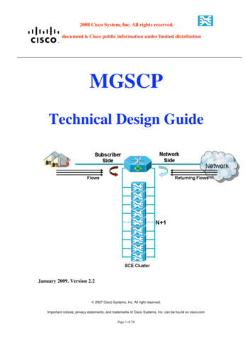
2008 Cisco System, Inc. All rights reserved.This document is Cisco public information under limited distributionMGSCPTechnical Design GuideJanuary 2009, Version 2.2 2007 Cisco Systems, Inc. All right reserved.Important notices, privacy statements, and trademarks of Cisco Systems, Inc. can be found on cisco.comPage 1 of 58
2008 Cisco System, Inc. All rights reserved.This document is Cisco public information under limited distribution Table of ContentsScope and Purpose.3Solution Overview .4CISCO 7600 BASED SOLUTION OVERVIEW .5Solution Building Blocks .5EtherChannel / LACP .5EtherChannel Load Balancing .5Biased Distribution .7Determining the Hashing Destination.8Using Two EtherChannel Groups and a Cluster of SCE Platforms .9EtherChannel Protection Using LACP .12LACP Rehashing Enhancement during Link Failure.13VLAN Design and Considerations .15SCE Link Failure Reflection.19SCE Port Negotiation Mode .22SCE Flow Control Mode .23SCE Connection Mode .24Cisco 7600 HW and SW Requirements.25Cisco 7600 usage of WS-6704 & WS-6708 Line cards.26SM Support and Implementation .27Management and Reporting.32MGSCP Solutions Overview.33Option 1–Single Cisco 7600 L2 Switching and EtherChannel Load Balancing.33Option 2–Dual-Homed Cisco 7600 L2 Switching and EtherChannel Load Balancing .39Option 3–Single Cisco 7600 L3 Routing and EtherChannel Load Balancing .45Option 4– 10G MGSCP - Single Cisco 7600 L2 Switching and EtherChannel Load Balancing .51Terminology .57 2007 Cisco Systems, Inc. All right reserved.Important notices, privacy statements, and trademarks of Cisco Systems, Inc. can be found on cisco.comPage 2 of 58
2008 Cisco System, Inc. All rights reserved.This document is Cisco public information under limited distribution Scope and PurposeThe Cisco Multi-GbE Service Control Platform (MGSCP) provides a scalablesolution based on multiple Service Control Engine (SCE) platforms in an environmentwhere a single SCE platform is not sufficient, and includes the ability to monitor,control, and report the traffic of subscribers within this environment.This technical design guide describes the concept of the MGSCP solution. It alsoexplains how to implement the solution in Multi-Gigabit & Multi-10G Ethernetenvironments.The guide explains how to enable network insertion of SCE platforms by integratingthe MGCSP with other Cisco platforms such as the Cisco 7600 (which can beachieved by configuring the solution to distribute traffic between a set of SCEplatforms and their available Gigabit & 10G interfaces), and explains how loadbalancing between SCE platforms can be achieved.The guide describes various network topologies and configurations based onEtherChannel groups, VLANs and VLAN translation, and other mechanisms thatenable a scalable subscriber-aware distribution of traffic across a cluster of SCEplatforms, while ensuring that all traffic of a given subscriber is handled by the sameSCE platform and allowing the service provider to provide subscriber-aware andapplication-aware DPI functionality. The technical concepts of the differenttopologies and configurations are explained, allowing the appropriate networkinsertion solution to be built. 2007 Cisco Systems, Inc. All right reserved.Important notices, privacy statements, and trademarks of Cisco Systems, Inc. can be found on cisco.comPage 3 of 58
2008 Cisco System, Inc. All rights reserved.This document is Cisco public information under limited distribution Solution OverviewThe Cisco SCE platform manages IP traffic using a stateful processing mechanismbased on application and subscriber awareness.This mechanism, which supports a rich feature set, requires the SCE platform tocapture both the upstream and downstream flows of a session in order to statefullyclassify it and provide L7 processing at the application level. To process anapplication that is implemented with a bundle of flows, such as FTP or SIP, the SCEplatform needs to process all the flows that comprise a session of this application.Furthermore, when the SCE platform is configured to implement per subscriberreporting or control (which is sometimes referred to as subscriber awareness), it mustprocess all traffic flows that a given subscriber generates.These requirements can impose a challenge when inserting SCE platforms intonetworks because asymmetric routing is often implemented in these networks and thetwo directions of a single session or the many flows of a specific subscriber may besplit between different links.Cisco SCE platforms are typically inserted into a network by using a bump-in-thewire approach. SCE platforms are transparent at Layer 2 and Layer 3, so bump-in-thewire installation involves cutting a network link and inserting an SCE platform.The Cisco SCE 8000 includes the support for up to four 10G Ethernet interfaces,while the SCE 2020 support up to four Gigabit Ethernet interfaces. This provides aninsertion solution for up to two 10G & Gigabit Ethernet links, even in the case wherethese links include asymmetric routing. The ability to support only two links creates achallenge when there is a need to support a high-speed environment with dual-homedor split flows over more than two links.This guide explains how to overcome these challenges by using the Cisco SCEplatform together with additional Cisco platforms. The solution has been designed byCisco as an integrated architecture that takes these platform and technology together. 2007 Cisco Systems, Inc. All right reserved.Important notices, privacy statements, and trademarks of Cisco Systems, Inc. can be found on cisco.comPage 4 of 58
2008 Cisco System, Inc. All rights reserved.This document is Cisco public information under limited distribution Cisco 7600 Based Solution OverviewSolution Building BlocksEtherChannel / LACPThe MGSCP solution uses EtherChannel (EC) and the Link Aggregation ControlProtocol (LACP) 802.3ad to enable scaling the SCE platform by sending the traffic toan EtherChannel. EtherChannel load balancing is used to distribute the traffic overseveral SCE platforms. LACP is used to manage the health of the EtherChannelgroup.EtherChannel Load BalancingOriginally, EtherChannel was designed to aggregate several physical Ethernet linksand logically represent them as a single interface (see graphic).The EtherChannel mechanism balances the traffic between the physical interfacesusing a deterministic hashing algorithm. This algorithm uses a predefined field in thepacket header and outputs a fixed Result Bundle Hash (RBH) value that determineswhich link to use.The predefined field can take one of the following values:-dst-ip—Destination IP addressesdst-mac—Destination MAC addressesdst-port—Destination Layer 4 portmpls—Load balancing for MPLS packetssrc-dst-ip—Source and destination IP addressessrc-dst-mac—Source and destination MAC addressessrc-dst-port—Source and destination Layer 4 portsrc-ip—Source IP addresses 2007 Cisco Systems, Inc. All right reserved.Important notices, privacy statements, and trademarks of Cisco Systems, Inc. can be found on cisco.comPage 5 of 58
2008 Cisco System, Inc. All rights reserved.This document is Cisco public information under limited distribution-src-mac—Source MAC addressessrc-port—Source Layer 4 portThe MGSCP solution takes advantage of this mechanism and uses the Source andDestination IP addresses (src-ip and dst-ip) as the predefined field to use for EC loadbalancing on a single Cisco 7600 platform.Because the Cisco 7600 supports distributed forwarding, it can use a different hashingalgorithm on each Line Card that has a DFC installed. This unique capability enablesa single Cisco 7600 to perform the functionality shown in the following graphic.(Load-balancing is based on the source IP on one Line Card, and based on destinationIP on the second Line Card)The Cisco-proprietary hash algorithm computes a value in the range of 0 to 7 for theRBH. With these eight RBH values as a basis, a particular port in the EtherChannel ischosen. The port setup includes a mask that indicates which values the port acceptsfor transmission.A single EtherChannel can have up to eight active ports. With the maximum numberof active ports in a single EtherChannel, each port accepts only one value. If you havefour active ports in the EtherChannel, each port accepts two values, and so on. Thefollowing table lists the number of values that each port accepts, which depends onthe number of active ports in the EtherChannel:Number of active portsin the EtherChannel87Load balancing1:1:1:1:1:1:1:12:1:1:1:1:1:1 2007 Cisco Systems, Inc. All right reserved.Important notices, privacy statements, and trademarks of Cisco Systems, Inc. can be found on cisco.comPage 6 of 58
2008 Cisco System, Inc. All rights reserved.This document is Cisco public information under limited :4This table lists the number of values (calculated by the hash algorithm) that aparticular port accepts. You cannot control the port that a particular flow uses, butonly influence the load balance with a frame distribution method that results in thegreatest variety.Note: The Cisco 7600 Sup720 card identifies MPLS packets based on the EthernetType field (0x8847/0x8848). For these packets, the input to the hash block shouldpreferably be the IP information extracted from the L3 portion of the packet.Typically, when the packet contains three or fewer labels, Sup720 would attempt toparse the underlying IP to obtain the IP addresses for the hash.Biased DistributionBecause the EC hash result has eight distinct values, dividing these values betweenworking ports is only unbiased when working with 1, 2, 4, or 8 ports. Any otherconfiguration creates a biased load.The following table describes the load balance for each option:Number of ports in theEtherChannel87654321Load balancing1/8, 1/8, 1/8, 1/8, 1/8, 1/8, 1/8, 1/81/4, 1/8, 1/8, 1/8, 1/8, 1/8, 1/81/4, 1/4, 1/8, 1/8, 1/8, 1/81/4, 1/4, 1/4, 1/8, 1/81/4,1/4, 1/4, 1/43/8, 3/8, 1/41/2, 1/21From this table it is clear that using 3, 5, 6, or 7 active ports in an EC bundle providespoor load balancing, because some ports get up to twice the load of others.Recommendation:Use 2, 4, or 8 active ports per EtherChannel to achieve an effective load balancing. 2007 Cisco Systems, Inc. All right reserved.Important notices, privacy statements, and trademarks of Cisco Systems, Inc. can be found on cisco.comPage 7 of 58
2008 Cisco System, Inc. All rights reserved.This document is Cisco public information under limited distributionDetermining the Hashing DestinationThe load-balancing algorithm is deterministic. To ascertain the EC port that a specificIP address will use, run the following commands:Cisco 7600 Load-Balancing Configuration7600#remote login switchTrying Switch .Entering CONSOLE for SwitchType " C C C" to end this session7600#test etherchannel load-balance interface port-channel 100 ip 192.168.1.1Computed RBH: 0x4Would select Gi4/1 of Po100You can predict the load-balancing scheme and plan accordingly, as illustrated in thefollowing table.IP ted RBH0x40x70x60x10x00x30x20x5Selected InterfaceGi4/1Gi4/5Gi4/1Gi4/5Gi4/1Gi4/5Gi4/1Gi4/5 2007 Cisco Systems, Inc. All right reserved.Important notices, privacy statements, and trademarks of Cisco Systems, Inc. can be found on cisco.comPage 8 of 58
2008 Cisco System, Inc. All rights reserved.This document is Cisco public information under limited distributionUsing Two EtherChannel Groups and a Cluster of SCE PlatformsA cluster of SCE platforms can be connected to a Cisco 7600 to perform servicecontrol processing. The traffic load within the specific environment determines theexact number of SCE platforms required.The Cisco 7600 configuration should include two EtherChannel groups. OneEtherChannel group will be connected to the subscriber interface of the SCE platformand the other group to the network interface (an example is shown in the graphic inthis section).To view the number of links per EtherChannel group, use the following command:Cisco 7600 Links per EtherChannel7600#sh etherchannelChannel-group listing:----------------------Group: 100---------Group state L2Ports: 3 Maxports 16Port-channels: 1 Max Port-channels 16Protocol: LACPMinimum Links: 0Group: 200---------Group state L2Ports: 3 Maxports 16Port-channels: 1 Max Port-channels 16Protocol: LACPMinimum Links: 0To view the EtherChannel status, use the following command:Cisco 7600 EtherChannel Status7600#sh etherchannel summaryFlags: D - downP - bundled in port-channelI - stand-alone s - suspendedH - Hot-standby (LACP only)R - Layer3 S - Layer2U - in use f - failed to allocate aggregator 2007 Cisco Systems, Inc. All right reserved.Important notices, privacy statements, and trademarks of Cisco Systems, Inc. can be found on cisco.comPage 9 of 58
2008 Cisco System, Inc. All rights reserved.This document is Cisco public information under limited distributionM - not in use, minimum links not metu - unsuitable for bundlingw - waiting to be aggregatedNumber of channel-groups in use: 2Number of aggregators:2Group Port-channel Protocol Ports------ ------------- ----------- ----------------------------------------------100 Po100(SU)LACPGi4/1(P) Gi4/3(P) Gi4/5(H)200 Po200(SU)LACPGi4/2(P) Gi4/4(P) Gi4/6(H)Because the SCE platform uses a stateful mechanism it must examine both theupstream and downstream of a flow in order to statefully classify the flow and provideL7 processing at the application level. Therefore the order in which the SCE platformsare connected in the EtherChannel group must be carefully designed, otherwiseupstream and downstream sides of a single flow will be forwarded to different SCEplatforms.An example of how to connect multiple SCE platforms is shown in the followinggraphic where: Interface Gi4/1 from EtherChannel group 100 and interface Gi4/2 fromEtherChannel group 200 are connected to SCE1. Interface Gi4/3 from EtherChannel group 100 and interface Gi4/4 fromEtherChannel group 200 are connected to SCE2. Interface Gi4/5 from EtherChannel group 100 and interface Gi4/6 fromEtherChannel group 200 are connected to SCE3. 2007 Cisco Systems, Inc. All right reserved.Important notices, privacy statements, and trademarks of Cisco Systems, Inc. can be found on cisco.comPage 10 of 58
2008 Cisco System, Inc. All rights reserved.This document is Cisco public information under limited distributionAnother key feature that needs to be configured for this setup is load balancing basedon Source IP for traffic arriving from the subscriber side and load balancing based onDestination IP for traffic arriving from the network side.The ability to perform this load balancing in one chassis has been introduced in Cisco6500 IOS version 12.2(18)SXF and 7600 12.2(xx)SRB. (Prior to the 12.2(18)SXFSW release only one hashing was allowed per chassis.) The code now allows using adifferent hashing function for each DFC so that different slots can provide differentfunctions (that is, one Sup720 card will hash based on the Destination IP and anotherDFC card will hash based on the Source IP, or vice versa). When scaling the solutionto multiple 10GE ports per chassis it is recommended to use the DFCs on the IngressLine Cards to perform the distributed hashing.Notes : The load balancing function is performed at the ingress port (for instance,interfaces T2/1 and T3/1 in the preceding graphic), and not at the EtherChannelinterface facing the SCE platforms.The 7600 load balancing is done on a single IP Address basis, this means that in acase of Multi-IP Subscribers the IPs may not hand up on the same SCE. Thissituation may impact the ability to provide the service for Multi-IP Subscribers.Supervisor and Line Card load balancing is configured at the global configurationlevel: The first line in the configuration file that is not for a specific Line Card refers tothe Supervisor load-balancing method. Additional lines can be added to the configuration file for configuration per LineCard.The following code sample illustrates this:Cisco 7600 EtherChannel Load-Balancing Configurationport-channel per-module load-balanceport-channel load-balance dst-ipport-channel load-balance src-ip module 2 2007 Cisco Systems, Inc. All right reserved.Important notices, privacy statements, and trademarks of Cisco Systems, Inc. can be found on cisco.comPage 11 of 58
2008 Cisco System, Inc. All rights reserved.This document is Cisco public information under limited distributionEtherChannel Protection Using LACPEtherChannel service protection can be implemented using an LACP failovermechanism. The LACP mechanism allows you to define N M redundancy, where upto eight active ports and up to eight failover/standby ports can be defined. You canactivate EtherChannel failover by configuring the max-bundle parameter of anEtherChannel interface, which is available with the LACP protocol.If an SCE platform fails, the traffic that is going through that SCE platform is cut off.The EtherChannel mechanism of the two EtherChannel groups detects this, stopssending traffic to the failed SCE platform, and redistributes the traffic to a differentSCE platform. It is important to understand that redistribution of the traffic takesplace.Cisco 7600 LACP Interface per Bundle Configurationinterface Port-channel100description Subscriber Portchannel VLAN 100 switchportswitchport trunk encapsulation dot1qswitchport trunk native vlan 100switchport trunk allowed vlan 100switchport mode trunkload-interval 30spanning-tree bpdufilter enablelacp max-bundle 2lacp direct-loadswapIn the preceding example the LACP max-bundle was set to 2; it should be set withvalues of 2, 4, or 8 depending on the number of active ports in the EC.A higher lacp port-priority priority (see previous example) means a lower priorityin the LACP. Default values are used for all active ports; the priority is changed onlyfor the standby interface. If one of the SCE platforms or links in the EtherChannelbundle fails, the LACP algorithm will activate the standby port or unit.During normal operation the Cisco 7600 assigns the eight RBH values to the activeports in a bundle, starting from the lowest port. In the case of a component failure or alink going down, the Cisco 7600 reassigns the affected RBH values to all active portsin the bundle, again starting with the lowest port. This means that if the highest portgoes down the impact is relatively low, but if the lowest port in the bundle goes downthe impact is higher and may result in a complete reshuffling of the traffic betweenthe SCE platforms. 2007 Cisco Systems, Inc. All right reserved.Important notices, privacy statements, and trademarks of Cisco Systems, Inc. can be found on cisco.comPage 12 of 58
2008 Cisco System, Inc. All rights reserved.This document is Cisco public information under limited distributionLACP Rehashing Enhancement during Link FailureThe assignment of the RBH values during a link failure was enhanced with the 7600IOS version 12.2(33)SRC with the introduction of the LACP Single Fault Direct LoadBalance Swapping feature on a port channel. (Note : This functionality is onlyavailable with the 7600 platform and not with the 6500).This command can be used for only a single link/port failure. If a second failureoccurs before the first failure recovers, the loadshare bits for member links arerecomputed.LACP : Direct Loadswap feature provides a solution in a case of a member-link goesdown in an EtherChannel, instead of reassigning the load balance bits to all themember-links (whose priority is lesser than the failing port) the load-balance bits aredirectly assigned from the failing port to the newly bundled port. When the failed portcomes up again it retains the load balance bits which it possessed before failing andthe port which replaced it is again unbundled.This feature works with respect to the original state of the EtherChannel that isconfigured. i.e. when there is a second link going down the method falls back to roundrobin.This example shows how to enable LACP single fault direct load swapping on portchannel 100:Cisco 7600 LACP Direct-loadswapinterface Port-channel 100description Subscriber Portchannel VLAN 100 switchportswitchport trunk encapsulation dot1qswitchport trunk native vlan 100switchport trunk allowed vlan 100switchport mode trunkload-interval 30spanning-tree bpdufilter enablelacp max-bundle 2lacp direct-loadswap 2007 Cisco Systems, Inc. All right reserved.Important notices, privacy statements, and trademarks of Cisco Systems, Inc. can be found on cisco.comPage 13 of 58
2008 Cisco System, Inc. All rights reserved.This document is Cisco public information under limited distributionRecommendation:If IOS version 12.2(33)SRC and above is in use, use the lacp direct-loadswap function when possible in order to achieve the most efficient recovery from a LinkFailure.See details in the following section.In case where an older IOS version then 12.2(33)SRC is in use it is recommended toplace the standby SCE/link in the middle. For example : in the case of a 4 1redundancy, links 1, 2, 4, and 5 should be active, and link 3 is in standby. You canconfigure this by setting the lacp port-priority option for the standby port to itshighest value.This configuration will provide the most efficient failover, which will have the lowestimpact on the service during a link failover. 2007 Cisco Systems, Inc. All right reserved.Important notices, privacy statements, and trademarks of Cisco Systems, Inc. can be found on cisco.comPage 14 of 58
2008 Cisco System, Inc. All rights reserved.This document is Cisco public information under limited distributionVLAN Design and ConsiderationsIn many MGSCP solution topologies, VLANs are a major consideration in design andimplementation. In these cases, the actual use of VLANs is determined by the specifictopology.Cisco 7600 ports that are connected to the SCE platform can be configured as eitherAccess or Trunk ports. Access ports should be used when only one VLAN is to besupported. Trunk ports should be used when multiple VLANs are to be supportedeither during the first phase of deployment or in the future.When using the Trunk port option, packets with VLAN tags pass through the Trunkports and should be modified/translated in order to force traffic to be switched via theSCE cluster.This functionality requires using a VLAN tag translation mechanism that is supportedby the Cisco 7600.Note: The simplest implementations of the MGSCP solution do not require VLANtranslation.Vlan Translation by the Cisco 7600IOS supports VLAN translation (know as VLAN mapping) per port. Using thisfeature, it is easy to set a mapping between the VLAN tags on the subscriber sidetrunks to the VLAN tags on the network side trunks and vice versa.Because the configuration is done per port group of the Cisco 7600 Line Card itmeans that a group of ports requiring the same VLAN mapping should be located onthe same Line Card (or same port group in a Line Card). 2007 Cisco Systems, Inc. All right reserved.Important notices, privacy statements, and trademarks of Cisco Systems, Inc. can be found on cisco.comPage 15 of 58
2008 Cisco System, Inc. All rights reserved.This document is Cisco public information under limited distributionCisco 7600 switchport vlan mappingTo map the traffic arriving on the VLAN original-vlan-id to the VLAN translated-vlan-id and the traffic that is internally tagged with the VLAN translated-vlan-id with the VLAN original-vlan-id before leaving the port, usethe switchport vlan mapping command. To clear the mapping between a pair ofVLANs or clear all the mappings that are configured on the switch port, use the noform of the command.Cisco 7600 VLAN Translation Command Syntaxswitchport vlan mapping original-vlan-id translated-vlan-idno switchport vlan mapping {{original-vlan-id translated-vlan-id} all}Cisco 7600 VLAN Translation Configurationinterface GigabitEthernet4/1description Connected to SCE1 SUB switchportswitchport trunk encapsulation dot1qswitchport trunk native vlan 100switchport trunk allowed vlan 100switchport mode trunkswitchport vlan mapping enableswitchport vlan mapping 200 100no ip addressload-interval 30 2007 Cisco Systems, Inc. All right reserved.Important notices, privacy statements, and trademarks of Cisco Systems, Inc. can be found on cisco.comPage 16 of 58
2008 Cisco System, Inc. All rights reserved.This document is Cisco public information under limited distributionflowcontrol send offno cdp enablespanning-tree bpdufilter enablechannel-protocol lacpchannel-group 100 mode active!interface GigabitEthernet4/2description Connected to SCE1 NET switchportswitchport trunk encapsulation dot1qswitchport trunk native vlan 200switchport trunk allowed vlan 200switchport mode trunkswitchport vlan mapping 200 100no ip addressload-interval 30flowcontrol send offno cdp enablespanning-tree bpdufilter enablechannel-protocol lacpchannel-group 200 mode activeNote: Translation (mapping) is only configured on one side of the loop and is used forboth incoming and outgoing VLAN tags.VLAN mapping is configured on interface Gi4/2 but is not enabled.Note: The CDP protocol must be disabled on the 7600 interface facing the SCEplatform port when implementing this solution; this prevents the Cisco 7600 fromsending CDP error messages. 2007 Cisco Systems, Inc. All right reserved.Important notices, privacy statements, and trademarks of Cisco Systems, Inc. can be found on cisco.comPage 17 of 58
2008 Cisco System, Inc. All rights reserved.This document is Cisco public information under limited distributionVLAN Translation and STP:Where Spanning Tree Protocol (STP) is deployed prior to SCE platform/MGSCPdeployment, some design consideration should be taken into account beforeimplementing VLAN translation. This is because STP BPDU packets already includea VLAN ID and in that case VLAN translation can seriously affects the properoperation of STP.IOS handles this issue by running an intelligent VLAN translation/mapping; ittranslates the VLAN value both at the Ethernet header level and at the Ethernetpayload level.Recommendation: Implement VLAN translation on the Cisco 7600 platform.Disable BPDU processing on ports facing the SCE platform. 2007 Cisco Systems, Inc. All right reserved.Important notices, privacy statements, and trademarks of Cisco Systems, Inc. can be found on cisco.comPage 18 of 58
2008 Cisco System, Inc. All rights reserved.This document is Cisco public information under limited distributionSCE Link Failure ReflectionLink failure reflection is an important part of the solution that allows the SCEplatform to behave as a bump-in-the-wire.The link failure reflection feature reflects a link failure that occurs on one side of thelink to the other side. This ensures that the Cisco 7600 ports connected to the sameSCE platform are synchronized and fail at the same time, and avoids the need to waitfor the LACP to discover that a failure took place. This avoids “black-holing”situations where the switch continues to send traffic to an SCE platform when theother side of the SCE platform is disconnected.There are several options for implementing the link failure reflection feature. Theappropriate option depends on the way the SCE platform ports are physicallyconnected to the Cisco 7600 and the redundancy requirement of the network design.By default, link failure reflection is disabled. Enabling and disabling link failurerefl
an EtherChannel. EtherChannel load balancing is used to distribute the traffic over several SCE platforms. LACP is used to manage the health of the EtherChannel group. EtherChannel Load Balancing Originally, EtherChannel was designed to aggregate several physical Ethernet links and logically represent them as a single interface (see graphic).