Transcription
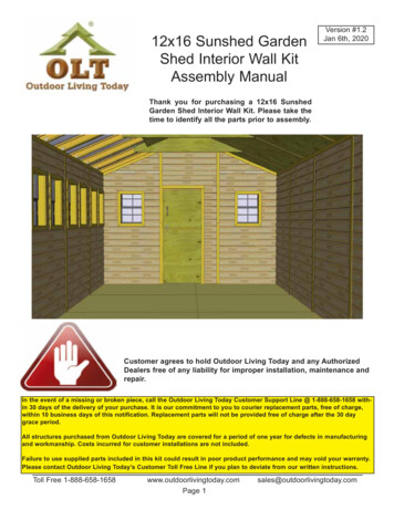
12x16 Sunshed GardenShed Interior Wall KitAssembly ManualVersion #1.2Jan 6th, 2020Thank you for purchasing a 12x16 SunshedGarden Shed Interior Wall Kit. Please take thetime to identify all the parts prior to assembly.Customer agrees to hold Outdoor Living Today and any AuthorizedDealers free of any liability for improper installation, maintenance andrepair.In the event of a missing or broken piece, call the Outdoor Living Today Customer Support Line @ 1-888-658-1658 within 30 days of the delivery of your purchase. It is our commitment to you to courier replacement parts, free of charge,within 10 business days of this notification. Replacement parts will not be provided free of charge after the 30 daygrace period.All structures purchased from Outdoor Living Today are covered for a period of one year for defects in manufacturingand workmanship. Costs incurred for customer installations are not included.Failure to use supplied parts included in this kit could result in poor product performance and may void your warranty.Please contact Outdoor Living Today’s Customer Toll Free Line if you plan to deviate from our written instructions.Toll Free 1-888-658-1658www.outdoorlivingtoday.comPage 1sales@outdoorlivingtoday.com
Thank you for purchasing our 12x16 Sunshed Garden Shed Interior Wall.Please take the time to identify all the parts prior to assembly.A. Ceiling Section1A: 2 - 3/4” x 2 1/2” x 71” - Ceiling Gable Cleats Long2A: 2 - 3/4” x 2 1/2” x 30” - Ceiling Gable Cleats Short3A: 1 - 3” x 5 3/4” x 20” - Ridge Cap Sleeve Front4A: 3 - 3” x 5 3/4” x 44 3/4” - Ridge Cap Sleeve Middle5A: 3 - 1” x 5 3/4” x 17 3/4” - Ridge Cap Sleeve Rear6A: 4 - 3/4” x 3 1/2” x 28 1/2” - Gusset Cleats7A: 4 - 1 1/2” x 2 1/2” x 68” - Roof Cleats Long8A: 1 - 3/8” x 21” x 71 3/4” - Long Ceiling Plywood Front9A: 3 - 3/8” x 44 3/4” x 71 3/4” - Long Ceiling Plywood Center10A: 1 - 3/8” x 18 3/4” x 71 3/4” - Long Ceiling Plywood Rear11A: 1 - 3/8” x 21” x 30 3/4” - Short Ceiling Plywood Front12A: 4 - 1 1/2” x 2 1/2” x 30” - Roof Cleats Short13A: 3 - 3/8” x 44 3/4” x 30 3/4” - Short Ceiling Plywood Center14A: 1 - 3/8” x 18 3/4” x 30 3/4” - Short Ceiling Plywood Rear16A: 8 - 1/2” x 3 1/2” x 19” - Interior SoffitsB. Wall Section1B: 8 - 1 1/2” x 2 1/2” x 19” - Interior Wall Cleats2B: 2 - 42 3/4”w x 82 1/2”h - Solid Wall Panel Left & Right3B: 2 - 45 1/4”w x 82 1/2”h - Solid Wall Panel Center4B: 2 - 42 3/4”w x 82 1/2”h - Double Window Wall Panel Left & Right5B: 2 - 45 1/4”w x 82 1/2”h - Double Window Wall Panel Center6B: 4 - 45”w x 82 1/2”h - Single Window Wall Panels7B: 1 - 45 1/4”w x 82 1/2”h - Solid Rear Wall Panel8B: 1 - 11 3/4”w x 74 1/2”h - Narrow Front Wall Panel10B: 1 - 45 1/4”w x 35 5/8”h - Gable Center Panel (Front)10B: 1 - 45 1/4”w x 26 3/4”h - Gable Center Panel (Rear)11B: 2 - 44 3/4”w x 18 1/16”h - Gable Panel Left12B: 2 - 44 3/4”w x 18 1/16”h - Gable Panel Right13B: 1 - 3/4” x 3 1/2” x 31 1/2” - Top Plate for Bottom Dutch Door14B: 1 - 3/8” x 31 3/8” x 29 3/16” - Top Door Plywood15B: 1 - 3/8” x 31 3/8” x 41 3/16” - Bottom Door PlywoodC. Trim Section1C: 1 - 7/8” x 2” x 72 1/2” - Vertical Door Stop (Jamb)2C: 1 - 7/8” x 1/2” x 72 1/2” - Vertical Door Stop (Narrow Wall)3C: 1 - 3/4” x 2” x 33 5/8” - Top Horizontal Door Stop4C: 1 - 1/4” x 2” x 72 5/8” - Vertical Door Trim5C: 1 - 1/2” x 2 1/2” x 33 1/2” - Horizontal Door Trim8C: 4 - 1/4” x 2” x 71 1/4” - Gable Ceiling Trims11C: 8 - 1/4” x 2” x 55” - Gable Trims (Top & Bttm.)7C: 6 - 1/4” x 2” x 58” - Horizontal Side Wall Trims12C: 6 - 1/4” x 2” x 82 1/4” - Vertical Side Wall Trims13C: 4 - 1/2” x 1 1/2” x 41 1/4” - Single Rafter Bottom Trims14C: 3 - 1/2” x 3” x 41 1/4” - Double Rafter Bottom Trims15A: 4 - 1/4” x 2 1/2” x 31” - Ceiling Trims15C: 4 - 21 1/16” x 26 3/8” - Large Window Inserts16C: 8 - 16 3/4” x 24” - Small Window InsertsD. Potting Shelves - Optional1D - Potting Shelf Legs - 20 pcs @1 1/2” x 2 1/2” x 35”2D - Extra Siding PiecesToll Free 1-888-658-1658www.outdoorlivingtoday.comPage 2Steps1123345678910111213Steps1415 - 16171819202122232624, 2625, 2627 - les@outdoorlivingtoday.com
12X16 Sunshed Interior Wall Kit HARDWARE PACKAGEHardware Kit(Provided)2 1/2”N1 - 1 1/2” Finishing Nails - 350S1 - 2 1/2” Screws - 1201 1/4”BR1 - Square Drive BitS2 - 1 1/4” Screws - 275SB1 - 3/4” Screws -12 pcsBlack HeadedY3 - Black HandleTools RequiredHammerMed. Barrel Bolt(Not Provided)Screw Gun/Drill Tape MeasureLevel1/8” Drill Bit2 LaddersSafety Equipment RequiredWood ClampSafety Glasses(Not Provided)Work GlovesOptional Materials and Tools - Not Included in KitMaterials to Insulate Shed prior to installing Interior Wall Kit2” thick Foam Board Insulation550 sq ft. (covers walls and ceiling)180 sq ft additional for floor6 mm Poly - Air Vapor Barrier -Tools Staple GunUtility KnifeCaulking Gun and CaulkingToll Free 1-888-658-1658www.outdoorlivingtoday.comPage 3sales@outdoorlivingtoday.com
A. Ceiling SectionExploded view of all parts necessary to complete Interior Ceiling Section. Please Identify all partsprior to starting your project.Ceiling Section ExplodedCeiling GableCleats 4 pcsRidge Cap Sleeves5 pcsCeiling Plywood(Rear) LongRafter Cleats 4 pcsGusset Cleats 4 pcsCeiling Plywood(Front) LongCeiling Plywood(Center) LongInterior Soffits 8 pcsCeiling Plywood (Front) Short -1 pcsCeiling Plywood (Rear) Short -1 pcsCeiling Plywood Center Short - 2 pcCeiling Trim 4 pcsPartsHardwareLocate long and short cleats. Position cleat on top1A - Ceiling Gable Cleats S1 - 2 1/2” Screwsof gable framing tight against rafter. Clamp and screw(3/4” x 2 1/2” x 71”) x 2x 12 totalto gable frame with 3 - 2 1/2” screws in short cleat2A - Ceiling Gable Cleatsand 3 - 2 1/2” screws in long cleat.(3/4” x 2 1/2” x 30”) x 21.Toll Free 1-888-658-1658www.outdoorlivingtoday.comPage 4sales@outdoorlivingtoday.com
1” GapPartsHardwareLift up the 20” Ridge Cap Sleeve and3A,4A,5A - Ridge Cap Sleeve S2 - 1 1/4” Screwsposition over ridge board near the door of(3” x 5 3/4” x 20”) x 1x 30 totalyour shed. Leave 1” gap from gable wall.(3” x 5 3/4” x 17 3/4”) x 1Screw from underside of sleeve using(3” x 5 3/4” x 44 3/4”) x 33 - 1 1/4” screws.2.3.Push second, third, and fourth sleeves (44 3/4”) tight between Gussets and attach asper Step 2. Attach final sleeve (17 3/4”) over Ridge Board at rear of shed. At the rear of yourshed leave a 1” gap between Gable and Ridge Sleeve as per Step 2.Gusset Cleats4.Locate Gusset Cleats (22.5 cut one end) andposition on Rafter flush with Gusset. AttachGusset Cleat to Rafter with 3 - 1 1/4” screws.Complete remaining three Gusset Cleats.Toll Free 1-888-658-1658Parts6A - Gusset Cleats(3/4” x 3 1/2” x 28 1/2”) x 4www.outdoorlivingtoday.comPage 5HardwareS2 - 1 1/4” Screwsx 12 totalsales@outdoorlivingtoday.com
Rafter Cleats5.Locate Roof Cleats and position flush withGusset and Gusset Cleat. Attach Roof Cleat toGusset and Gusset Cleat with 4 - 2 1/2” screwsper cleat.Parts7A - Roof Cleats Long(1 1/2” x 2 1/2” x 68”) x 4HardwareS1 - 2 1/2” Screwsx 16 totalParts8A - Long Ceiling Plywood(front)(3/8” x 21” x 71 3/4”) x 1HardwareS2 - 1 1/4” Screwsx 12 totalPartsLocate and position center ceiling plywood9A - Long Ceiling Plywood(44 3/4” wide) panels and position against Rafters(Center)and Roof Cleats. When positioned correctly,(3/8” x 44 3/4” x 71 3/4”) x 3attach to Rafter and Roof Cleat with12 - 1 1/4” screws. Complete three sections.HardwareS2 - 1 1/4” Screwsx 36 total6.Locate long ceiling plywood (21” wide) andposition up against rafter and ceiling gable cleat.Position squarely and attach with12 - 1 1/4” screws.7.Toll Free 1-888-658-1658www.outdoorlivingtoday.comPage 6sales@outdoorlivingtoday.com
8.Parts10A - Long CeilingPlywood (Rear)(3/8” x 18 3/4” x 71 3/4”) x 3HardwareS2 - 1 1/4” Screwsx 12 total9.Parts11A - Short CeilingPlywood (Front)(3/8” x 21” x 30 3/4”) x 1HardwareS2 - 1 1/4” Screwsx 8 totalLocate and position rear ceiling plywoodpanel (18 3/4” wide) and position against Raftersand Roof Cleats. When positioned correctly,attach to Rafter and Roof Cleat with12 - 1 1/4” screws. Complete three sections.Locate and position front ceiling plywoodpanel below Rafter and Gable Cleat. Attach panelto Rafter and Gable Cleat with 8 - 1 1/4” screws.PartsHardwareLocate Roof Cleats Short and one Short Ceiling12A- Roof Cleat Short S1 - 2 1/2” ScrewsPanel. Place Roof Cleat Short flush to Gusset. Attach(1 1/2” x 2 1/2” x 30”) x 4x 12 totalCleat to Gusset using 3 - 2 1/2” screws per Cleat. Holda ceiling panel flush to rafter to help you line up thecleat.10.Toll Free 1-888-658-1658www.outdoorlivingtoday.comPage 7sales@outdoorlivingtoday.com
PartsLocate and position center ceiling plywood13A - Short Ceilingpanels below Rafter and Short Roof Cleat. AttachPlywood (Center)panel to Rafter and Gable Cleat with(3/8” x 44 3/4” x 30 3/4”) x 38 - 1 1/4” screws. Complete three panels.HardwareS2 - 1 1/4” Screwsx 24 totalParts14A - Short CeilingPlywood (Rear)(3/8” x 18 3/4” x 30 3/4”) x 3HardwareS2 - 1 1/4” Screwsx 8 total11.12.Locate and position rear ceiling plywoodpanel below Gable Ceiling Cleat and Short RoofCleat. Attach panel to both Cleats with8 - 1 1/4” screws.Tight against PolygalSupport CleatTight againstPolygalFlushHardwarePartsLocate Interior Soffits. Interior Soffits sit tight up16A - Interior Soffits N1 - 1 1/2” Finishingagainst Polygal Panels and Polygal Support Cleats.Nails(1/2” x 3 1/2” x 19”) x 8Soffits may need to be cut short to fit correctly.x 16 totalAttach each with 4 - 1 1/2” Finishing Nails. Nail intoedge of short ceiling plywood. Complete all 8.13.Toll Free 1-888-658-1658www.outdoorlivingtoday.comPage 8sales@outdoorlivingtoday.com
B. Wall Section14.Position two Interior Wall Cleats againstside wall in corner. Attach each Cleat with2 - 2 1/2” screws. Attach cleats to each corner ofyour shed. Cleat provides an edge to screwInterior Wall Panel to in Step 15.Parts1B - Interior Wall Cleats(1 1/2” x 2 1/2” x 12”) x 8HardwareS1 - 2 1/2” Screwsx 16 totalSiding recessed onleft side of panel.15.Locate Left Solid Wall Panel (42 3/4” wide).The left panel will have wall siding recessed onthe left side as illustrated above. Position on wallstuds and secure with 6 - 1 1/4” screws.PartsHardware2B - Solid Wall Panel Left S2 - 1 1/4” Screws(42 3/4”w x 82 1/2”) x 1x 6 totalSiding recessed onright side of panel.16.Locate Right Solid Wall Panel(42 3/4” wide). The right panel will have wallsiding recessed on the right side as illustratedabove. Position on wall studs and secure with6 - 1 1/4” screws.Toll Free 1-888-658-1658PartsHardware2B - Solid Wall Panel Right S2 - 1 1/4” Screws(42 3/4”w x 82 1/2”) x 1x 16 totalwww.outdoorlivingtoday.comPage 9sales@outdoorlivingtoday.com
Pre-drill sidingwith 1/8” drill bit17.Locate Center Solid Wall Panel(45 1/4” wide). Center Wall Panels have sidingflush with plywood backing. Position betweenpreviously installed panels and secure with6 - 1 1/4” screws.Complete both center panels.18.Locate Double Window Wall Panels Left &Right (42 3/4” wide). the panels have recessedsiding as per Steps 15-16. Position on wall studsand secure as previously illustrated.Parts3B - Solid Wall PanelCenter(45 1/4”w x 82 1/2”) x 2HardwareS2 - 1 1/4” Screwsx 12 totalPartsHardware4B - Double Window Wall S2 - 1 1/4” ScrewsPanels (L&R)x 12 total(42 3/4”w x 82 1/2”) x 2Pre-drill sidingwith 1/8” drill bitPartsHardwareLocate Double Window Wall Center Panels5B - Double Window Wall S2 - 1 1/4” Screws(45 1/4” wide). Panel wall siding will be flush withPanels (Center)x 12 totalplywood backing. Position between previously(45 1/4”w x 82 1/2”) x 2installed panels on wall studs and secure with6 - 1 1/4” screws per panel. Complete both panels.19.Toll Free 1-888-658-1658www.outdoorlivingtoday.comPage 10sales@outdoorlivingtoday.com
20.Locate Single Window Wall Panels(45” wide). All single window wall panels are builtthe same. Position in front corner. Slide edge tightin corner against side wall plywood backing.Adjust panel so window openings match. Securewith 6 - 1 1/4” screws. Complete each corner.21.Locate Solid Center Wall Panel(45 1/4” wide). Center panel wall siding is flushwith plywood backing. Position betweenpreviously installed panels on wall studs andsecure with 6 - 1 1/4” screws.22.Position and attach Narrow Wall Panel nextto door on wall framing. Attach with6 - 1 1/4” screws.Toll Free 1-888-658-1658Parts6B - Single Window WallPanels(45”w x 82 1/2”) x 4HardwareS2 - 1 1/4” Screwsx 24 totalPartsHardware7B - Solid Rear Wall Panel S2 - 1 1/4” ScrewsCenterx 6 total(45 1/4”w x 82 1/2”) x 1Parts8B - Narrow Front WallPanel(11 3/4”w x 74 1/2”) x 1www.outdoorlivingtoday.comPage 11HardwareS2 - 1 1/4” Screwsx 6 totalsales@outdoorlivingtoday.com
Pre-drill siding with 1/8” drillbit before attaching GablePanel.23.Lift up Front Center Gable Panels and slidenotch up against roof Ridge Board. Once GablePanel is aligned correctly, attach to gable framingwith 4 - 1 1/4” screws.Parts10B - Front Gable CenterPanel(45 1/4” x 35 5/8”) x 1HardwareS2 - 1 1/4” Screwsx 4 totalGable siding overhangs wall siding.Pre-drill siding with 1/8” drillbit before attaching GablePanel.PartsHardwareLocate Front Gable Panel Left and position in11B - Front Gable Left S2 - 1 1/4” Screwsfront corner against gable framing. When positionedPanelx 4 totalcorrectly, gable siding will overhang window wall siding(44 3/4” x 18 1/16”) x 1with plywood backing pushed tight together. Attachwith 4 - 1 1/4” screws.24.Toll Free 1-888-658-1658www.outdoorlivingtoday.comPage 12sales@outdoorlivingtoday.com
25.Locate Front Gable Panel Right and position in front corner of gable framing. Position andattach as per Step 24.26.Parts12B - Front Gable RightPanel(44 3/4” x 18 1/16”) x 1Attach Rear Gable Panels as per Steps 23 - 25.HardwareS2 - 1 1/4” Screwsx 12 totalHardwareS2 - 1 1/4” Screwsx 4 totalParts10B - Rear Gable Center Panel(45 1/4” x 26 3/4”) x 111B - Front Gable Left Panel(44 3/4” x 18 1/16”) x 112B - Front Gable Right Panel(44 3/4” x 18 1/16”) x 127.To accomodate Interior Door Plywood, the existing top plate on bottom door must be removedfirst. Using a hammer, carefully pry off the top plate and remove any hardware.Toll Free 1-888-658-1658www.outdoorlivingtoday.comPage 13sales@outdoorlivingtoday.com
28.Position replacement top plate on bottomdoor and attach with 6 - 1 1/2” Finishing Nails.Replacement Top Plate will cap door siding.Parts13B - Top Plate for BottomDutch Door(3/4” x 3 1/2” x 31 1/2”) x 1HardwareN1 - 1 1/2”Finishing Nailsx 6 total29.Position top door plywood over door framing. Confirm it is evenly spaced on door framingand attach with 12 - 1 1/2” finishing nails.Parts14B - Top Door Plywood(3/8” x 31 3/8” x 29 3/16”) x 1HardwareN1 - 1 1/2”Finishing Nailsx 12 total30.Parts15B - Bottom Door Plywood(3/8” x 31 3/8” x 41 3/16”) x 1HardwareN1 - 1 1/2”Finishing Nailsx 12 totalPosition bottom door plywood on door.Position tight under new top cap and attach with12 - 1 1/2” finishing nails.Toll Free 1-888-658-1658www.outdoorlivingtoday.comPage 14sales@outdoorlivingtoday.com
C. Trim SectionPartsHardwareLocate all 3 door stops. Start on the door1C - Vertical Door Stop - Jamb S2 - 1 1/4” Screwsjamb side, position 2” wide stop against door(7/8” x 2” x 72 1/2”) x 1x 4 totaljamb and the edge of wall siding. Attach with4 - 1 1/4” screws.31.32.Position and attach the narrow wall doorstop on framing with 6 - 1 1/2” finishing nails.Parts2C - Vertical Door Stop Narrow Wall(7/8” x 1/2” x 72 1/2”) x 1HardwareN1 - 1 1/2”Finishing Nailsx 6 totalPartsHardwareTo complete the door stops, attach the3C - Top Horizontal Door Stop S2 - 1 1/4” ScrewsHorizontal Door Stop against Door Header and(3/4” x 2” x 33 5/8”) x 1x 3 totalattach with 3 - 1 1/4” Page 15sales@outdoorlivingtoday.com
34.Locate Vertical Door Trim. Vertical DoorTrim cover seams around the door and NarrowWall. Position each piece over Narrow WallDoor Stop and wall seam. Attach each with6 - 1 1/2” Finishing Nails.Parts4C - Vertical Door Trim(1/4” x 2” x 72 5/8”) x 1HardwareN1 - 1 1/2”Finishing Nailsx 6 totalFiller Trim attachedon backPartsLocate Horizontal Door Trim and position on5C - Horizontal Door TrimDoor Header, tight against vertical Trim from the(1/2” x 2 1/2” x 33 1/2”) x 1previous step. Horizontal trim will have an additional piece of wood pre-attached to the reverse faceto make it sit flush to the wall. Attach trim with3 - 1 1/2” Finishing Nails.35.Toll Free 1-888-658-1658www.outdoorlivingtoday.comPage 16HardwareN1 - 1 1/2”Finishing Nailsx 3 totalsales@outdoorlivingtoday.com
36.Locate Gable Ceiling Trims. Position againstgable wall siding and bottom of ceiling plywood. Trimswill butt up against Ridge Cap Sleeves and HorizontalSide wall Trims. Attach each piece with6 - 1 1/2” Finishing Nails. Complete front and rear ofshed.Parts8C - Gable CeilingTrims(1/4” x 2” x 71 1/4”) x 4PartsLocate Gable Trims. Gable Trims (Top) have a10C - Gable Trims (Top)22.5 cut at the top to match Gable Ceiling Trims.(1/4” x 2” x 55”) x 4Gable Trims (Bttm.) have a straight cut end and a11C - Gable Trims (Bttm.)bevel cut end. Gable Trim (Bttm.) will need to be(1/4” x 2” x 55”) x 4chopped at the bottom to fit your ceiling position.Both pieces have a bevel cut where they meet inthe middle. Attache each piece with3 - 1 1/2” Finishing Nails. Cover remaining seamson front walls.Complete front and rear of ge 17HardwareN1 - 1 1/2”Finishing Nailsx 24 totalHardwareN1 - 1 1/2”Finishing Nailsx 24 totalsales@outdoorlivingtoday.com
38.Parts7C - Horizontal SideWall Trims(1/4” x 2” x 58”) x 6HardwareN1 - 1 1/2”Finishing Nailsx 24 total39.Parts12C - Vertical Side WallTrims(1/4” x 2” x 82 1/4”) x 6HardwareN1 - 1 1/2”Finishing Nailsx 36 totalLocate Horizontal Side Wall Trims. Position trimsup against wall siding and below ceiling plywood andRafters. Evenly space trims on side walls and attacheach piece with 4 - 1 1/2” Finishing Nails.Locate Vertical Side Wall Trims. Position overseams in side walls on both sides of shed. Attacheach piece with 6 - 1 1/2” Finishing Nails.40.Attach Rafter Bottom Trims to cover underside of Rafters with Cedar Trim. Position underthe Rafter and fasten with5 - 1 1/2” Finishing Nails per piece.Toll Free 1-888-658-1658Parts13C,14C - RafterBottom Trims(1/2” x 1 1/2” x 41 1/4”) x 4(1/2” x 3” x 41 1/4”) x 3www.outdoorlivingtoday.comPage 18HardwareN1 - 1 1/2”Finishing Nailsx 36 totalsales@outdoorlivingtoday.com
41.Locate Ceiling Trims and position over seamevenly to cover gaps between long ceiling panels.Attach each trim piece with4 - 1 1/2” Finishing Nails.42.Locate the 4 large Window Inserts andposition in window cavity. Nail to window wallframing with 9 - 1 1/2” Finishing Nails from thebottom and sides. Complete the smaller windowinserts in the same fashion.Parts15A - Ceiling Trims(1/4” x 2 1/2” x 31”) x 4HardwareN1 - 1 1/2” FinishingNailsx 16 totalParts15C - Large Window Inserts(21 1/16” x 26 3/8”) x 416C - Small Window Inserts(16 3/4” x 24”) x 8HardwareN1 - 1 1/2”Finishing Nailsx 108 totalPartsBarrel Bolt &Door HandleHardwareSB1 - 3/4” BlackHead Screwsx 12 totalPre-drill sidingwith 1/8” drill bit.43.Attach barrel bolt to doorplywood. Male bolt attached to top while femaleto bottom door. Attach door handle to top door.Use 3/4” black headed screws for both pieces.Toll Free 1-888-658-1658www.outdoorlivingtoday.comPage 19sales@outdoorlivingtoday.com
D. Potting Shelves - Optional44. If you decide to use the Potting Shelves that came with your12x16 Sunshed, this Interior Kit includes 20 Shelf Legs (4 Legsper Shelf). The Legs that came with your Sunshed will have anglecut ends, which will not work with the Interior Kit.Fasten a square cut Leg in each corner of the shelf as illustrated,attach with 2 - 2 1/2” Screws per Leg.45.Parts1D - Potting Shelf Legs(1 1/2” x 2 1/2” x 35”) x 20HardwareS1 - 2 1/2” Screwsx 32 totalPosition the Potting Shelves inside your Sunshed as desired, but theabove configuration provides optimal sunlight exposure from the PolygalRoof and Windows. Attach the Shelves together with 2 - 2 1/2” Screws tomake them into a continuous Bench. You may also want to carefullyscrew the Bench to the wall in a couple concealed spots to keep it inplace. Extra 2 1/2” Screws will be included in your hardware pack for this.1-888-658-1658www.outdoorlivingtoday.comPage 20HardwareS1 - 2 1/2” Screwsx 10 to 14 totalsales@outdoorlivingtoday.com
Congratulations on assembling your 12x16 SunshedGarden Shed Interior Wall Kit!We value your feedback andwould like to hear back from youon how well we are doing in thefollowing areas:1. Customer Service2. On Time Shipping3. Motor Freight Delivery4. Quality of Materials5. Assembly Manual6. Overall Satisfaction.Please call, write or email us at:Outdoor Living TodayCanadian Address9393 287th StreetMaple Ridge, British ColumbiaCanada V2W 1L1Toll Line: 1.888.658.1658United States AddressP.O. Box 96Sumas, WashingtonUSA 98295 Fax: 1.604.462.5333Page 21The materials contained in thisAssembly Manual may be downloadedor copied provided that ALL copiesretain the copyright and any otherproprietary notices contained on thematerials. No material may bemodified, edited or taken out of contextsuch that its use creates a false ormisleading statement or impression asto the positions, statements or actions. sales@outdoorlivingtoday.com
Jan 06, 2020 · Shed Interior Wall Kit Assembly Manual Version #1.2 Jan 6th, 2020 In the event of a missing or broken piece, call the Outdoor Living Today Customer Support Line @ 1-888-658-1658 with-in 30 days of the delivery of your purchase. It is our commitment to you to courier replacement parts, free