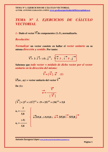
Transcription
Product brochureVersion01.00Vector Signal Generator SMATE200AThe production solution based on the SMU200AMay2005
The new standard in productionBased on the successful SMU200Aplatform, the SMATE200A is specifically designed for production environments. As such, the display and frontpanel user interface have been removed,the connectors moved to the rear, andperformance has been optimized forfastest setting times to improve factorythroughput. Like the SMU200A,however, the two-generators-in-oneconcept has been kept, occupying fourheight units – a plus for productionwhere space is at a premium. All of thisis available without compromising the2Vector Signal Generator SMATE200Aexcellent RF performance and baseband flexibility synonymous with the SMU200A.Speaking of flexibility, the modular designconcept of the SMATE200A meansthat the SMATE200A can easily beadapted to the needs of any application.Users have the choice of either 3 GHz or6 GHz RF outputs in one or two paths andmay opt for up to two completely independent baseband sources. As in the SMU200A, these sources may beused to produce complex signals in real-time or output preloaded waveforms fromthe internal arbitrary waveform generator.In addition to its inherent speed, the SMATE200A also offers a specialfunction to permit fast switching betweendifferent test signals. The multisegmentwaveform function allows users to easily combine waveforms, such as GSM andWCDMA, during test setup for even fastertests in production. This is just one of the SMATE200A’s numerous adaptations to the special requirements of theproduction environment.
Designed for productionOutstanding signal qualityTwo signal generators in one Very short setting times for frequencyand level (e.g. for frequency changes 2 ms over GPIB and 400 µs in Listmode) Fast Hop mode offering flexiblyaddressable frequency/level pairs; asfast as normal List mode Multisegment waveform functionenables fast switching between different test signals in waveform generator Special hardware triggers for basicfunctions Electronic attenuator for entire frequency and level range Status LEDs on front, connectors onrear Revised cooling concept for longerlife in production Very low SSB phase noise(typ. –135 dBc/Hz at f 1 GHz,20 kHz offset; typ. –140 dBc/Hz withlow phase noise option) Wideband noise of typ. –153 dBc( 5 MHz carrier offset, f 1 GHz,1 Hz measurement bandwidth) High output power of typ. 26 dBmwith high-power output option Very high level repeatability of typ.0.05 dB I/Q modulator with 200 MHz RF bandwidth Excellent ACLR performance of typ. 70 dB with 3GPP FDD Up to two completely independentsignal generators in one unit Choice of 3 GHz or 6 GHz frequencyoptions in one or two paths Up to two independent basebandsources that not only support realtime signal generation but also offerarbitrary waveform generation withup to 64 Msamples eachConnectivity Remote-controllable via LAN (GigabitEthernet) and GPIB User-definable triggers and markerscombined in one SCSI connector USB connectors for keyboard, mouseand memory stick VGA connector for an external displayVector Signal Generator SMATE200A3
Designed for productionDesigned for speed, the SMATE200Ais ideal for production lines where time iscritical. In remote control operation via theIEC/IEEE bus, setting times are 2 ms andeven faster in List mode ( 400 µs) wherepredetermined changes in frequency andlevel outputs may be specified in advance.New with the SMATE200A, the FastHop mode improves List mode capability by allowing users to arbitrarily addressup to 10 000 frequency/level pairs in anysequence via a serial bus, maximizing flexibility for test engineers. To further reducetest times, special hardware triggers arealso added, allowing control of frequentlyused functions, including RF ON/OFFand MODULATION ON/OFF. All of theseenhancements are designed to reduce thetotal cost of ownership in production environments.Instrument size and connectivity are alsocrucial elements in production. After all,lower space requirements mean lowercosts – particularly in a clean-room environment. Owing to its two-path concept,the SMATE200A occupies as littleas 50 % of the space required by a single-channel instrument. To allow easyrack installation, the SMATE200A isequipped with rear connectors as standard.Since production conditions requirerobust instruments, the SMATE200Ais designed for longer life. Its wear-free,electronic attenuator significantly lengthens product life over those instrumentsemploying mechanical attenuators. Othermeasures affording longer life includean optimized cooling system to keep theinstrument’s internal temperatures aslow as possible even when installed in arack with elevated ambient temperature.Lower temperatures reduce componentstress, thus increasing their lifespan.4Vector Signal Generator SMATE200ASetting time after a change in frequency
In production, one problem facing testengineers is the tradeoff between testtime and the need to stimulate eachDUT with varying, complex signals. The SMATE200A has the answer: themultisegment waveform function. Thisfeature allows users to combine up to100 waveforms stored simultaneouslyin memory, making it possible to switchbetween waveforms without first having to load each one separately. This notonly saves time during setup, but moreimportantly reduces the time for switching between waveforms to around 5 µs.Users even have the option to specifyseamless linking of waveforms to ensurephase stability – for example, duringreceiver tests where resynchronizationcan now be avoided.Another time-saving feature for testengineers, the Remote Desktop Connection of Microsoft’s Windows XP operating system, may be used via Gigabit LAN interface to check and modify test software as needed without having to be physically in frontWaveform 1Automatic repetition of partialwaveform within segmentResulting waveform in output RAMWaveform 2Segment 1Segment 2Segment 3Output signalWaveform 3Segment switching by SMATE200A user interface,IEC/IEEE bus,external trigger lineMultisegment waveform conceptof the SMATE200A. Of course,users on site may also access the SMATE200A user interface bymeans of the VGA output and a USBmouse and keyboard, same as for the SMU200A.Vector Signal Generator SMATE200A5
Outstanding signal qualityLike the SMU200A, the SMATE200A offers internal baseband generation of signals with up to80 MHz RF bandwidth. A flat frequencyresponse across this bandwidth is a prerequisite for generating signals withgood modulation characteristics such asEVM, and the SMATE200A makesno compromises. For RF bandwidthrequirements up to 200 MHz, users mayinput analog I/Q signals to each RF pathindependently. The SMATE200Aoffers all of this plus the same high spurious suppression that has come to beknown in the SMU200A.SSB phase noise / dBc(1 Hz)5,7 GHz2,1 GHz850 MHz100 MHz21010103104561071010Frequency offset / HzTypical single sideband phase noise at 100 MHz, 850 MHz, 2.1 GHz and 5.7 GHzwith the low phase noise optionRef -10 dBm* Att* RBW 30 kHz* VBW 300 kHz* SWT 2 s10 dB-20A-301 RM *CLRWRCLRWRSGLSG-40-50-60-70-80NONOR-90-100Center 2.14 GHzPRSpan 25.5 MHz PRN2.55 MHz/Tx CChanhannelnelBandwidth3.843.84 MMHzW-CDW-CDMAMA 3G3GPPPP FWFWDPowerAdAdjajacencentt CChannennelBandwidthSpacing3.84 MHz5 MHzLowerUpper-70.35 dB-70.83 dBAlAlteternarnatete ChChannannelelBandwidthSpacing3.84 MHz10 MHzLowerUpper-73.56 dB-73.86 dB-6.30 dBmACLR performance for 3GPP FDD (test model 1, 64 DPCHs)3RF 850 MHzRF 1900 MHzRF 2200 MHz210–15–2RF 850 MHzRF 1900 MHzRF 2200 MHz4–3–4–3–2–101f / HzFrequency response of internal basebandDelta / dBThis low phase noise performance coupled with the highly linear I/Q modulatorlends itself to the SMATE200A‘sexcellent ACLR and EVM measurementcapability. Both parameters are especially important to power amplifier manufacturers – even more so with implementation of advanced, complex modulation schemes. It is also worth mentioning that excellent ACLR and EVMcharacteristics may be achieved simultaneously using the same test signal.Again, the advantage is greater measurement �120–130–140–150–160–1701A / dBJust because the SMATE200A isdesigned for speed doesn’t mean it lacksin performance. The SMATE200Aships standard with the same excellentRF characteristics as the SMU200A,typically –135 dBc/Hz for a 1 GHz carrier at 20 kHz offset. In addition, usersmay opt for the low phase noise option toachieve even higher phase noise suppression, typically 5 dBc/Hz improvement. Thesuperior combination of speed and signalquality makes the SMATE200A theideal LO substitute.3234210–1–2–3–4–5– 100– 80– 60– 40– 20020406080Frequency offset from carrier / MHzFrequency response (mode: external wideband I/Q)6Vector Signal Generator SMATE200A100
With its two-path concept, the SMATE200A not only offers twoindependent RF sources, but also up totwo independent baseband generatorswhose signals can be digitally addedinternally. The result is a single instrument containing two units specificallydesigned to work together. This eliminates the need for external cabling, making setup both simple and compact.Ref* Att5 dBm20 dB10* RBW 300 kHzADelta 1 [T1 ]-62.44 dB20.032051282 MHzVBW 3 MHz* SWT 100 ms-101 RM *CLRWRMarker 1 [T1 ]-203.71 dBm20.032051282 MHz-30PRN-40-501-60-70-800 Hz5 MHz/Stop50 MHzSpurious suppression of the internal baseband generators3028High P ower26Normal2422Level/dB mThe high-precision level control of the SMATE200A is based on a temperature-controlled RMS detector. Thisnot only translates to high precision,but also to high level repeatability, typically around 0.05 dB. This characteristic is especially important in production,because it allows the exact same testconditions to be established repeatedlyover a long period of 0040004500500055006000R F /MHzTypical maximum output power over frequency (with high-power output option)Level Repeatability (2GHz, 0dBm, ALC ON)0.5CWInternal Baseband I/QExternal Baseband I/Q0.4Level Deviation in dBIn production, it is not uncommon tohave many lossy elements betweenthe signal generator and the DUT.To compensate, the generator musthave sufficient output power. The SMATE200A with its high-poweroutput option provides levels of typically 26 dBm. Opting for the high-power output option does not involve replacing theelectronic attenuator. It is thus able toconserve the wide output level range.0.30.20.10– 0.1– 0.2– 0.3– 0.4– 0.515:0015:3016:0016:3017:0017:3018:00TimeLevel repeatability of the SMATE200AVector Signal Generator SMATE200A7
ConnectivityVersatile connectivity of the SMATE200A combines classicRF BNC outputs with additional inputsand outputs through SCSI connectors.These connectors further simplify andspeed up installation during setup.SCSI connectorsAn external keyboard and a mouse ormemory stick can be connected via USBinterfaces on the rear panel. Likewise, aVGA output is available for connectingan external display.Connectors for PC peripheralsThe SMATE200A can be remotecontrolled via GPIB or LAN interfaces. With the introduction of the SMATE200A, the capability to utilize a Gigabit Ethernet is offered, yieldingshorter test times during production.IEC/IEEE busGbit LANRemote control of the SMATE200A via IEC/IEEE bus or Gigabit Ethernet LANModular designOwing to its modular design, the SMATE200A may be adaptedto virtually any requirement. As usersrequire new functionality, the appropriate options may be added later.Low total cost of ownership is more thanjust a motto with the SMATE200A– it applies to every aspect of the instrument, including its three-year calibrationcycle. This translates to significant costsavings and reduces system down time.Look inside the SMATE200A8Vector Signal Generator SMATE200A
Condensed dataFrequencyFrequency range100 kHz to 3 GHz / 6 GHzSetting time 2 msSetting time in List mode 400 µsLevelRangeRange with high-power outputoptionSetting timeSpectral purity (f 1 GHz)NonharmonicsCarrier offset 10 kHzCarrier offset 850 kHzSSB phase noise(20 kHz carrier offset, 1 Hz measurement bandwidth)Wideband noise(carrier offset 5 MHz, 1 Hz measurement bandwidth)ACLR performance3GPP FDD test model 1, 64 DPCHs–144 dBm to 13 dBm (PEP)[ 16 dBm in overrange]–144 dBm to 19 dBm (PEP)[ 26 dBm in overrange] 2 ms for f 3 GHz 4 ms for f 3 GHz –80 dBc –86 dBctyp. –135 dBctyp. –140 dBc with low phase noiseoptiontyp. –153 dBc (CW)typ. –149 dBc (I/Q modulation)typ. 70 dBI/Q bandwidth (RF)Internal80 MHzExternal200 MHzArbitrary waveform generatorMemory depthInterfaces16 Msamples / 64 MsamplesIEEE 488.2, LAN (Gigabit Ethernet),2 USB, 1 USB slave, VGAVector Signal Generator SMATE200A9
Ordering informationDesignationTypeOrder No. SMATE200A1400.7005.02100 kHz to 3 GHz SMATE-B1031401.1000.02100 kHz to 6 GHz SMATE-B1061401.1200.02Vector Signal Generator1)Including power cable, Quick Start Guide and CD-ROM (with operating and service manual)OptionsRF Path ALow Phase Noise and analog modulation FM/ΦM SMATE-B221401.2507.02High-Power Output SMATE-B311401.1800.02100 kHz to 3 GHz SMATE-B2031401.1400.02100 kHz to 6 GHz SMATE-B2061401.1600.02RF Path BLow Phase Noise and analog modulation FM/ΦM SMATE-B221401.2507.02High-Power Output SMATE-B361401.2107.02 SMATE-B101401.2707.02BasebandBaseband Generator with ARB (64 Msamples) and Digital Modulation (realtime)Baseband Generator with ARB (16 Msamples) and Digital Modulation (realtime) SMATE-B111401.2807.02Baseband Main Module SMATE-B131401.2907.02Differential I/Q Output SMATE-B161401.2407.02 SMATE-K401404.5107.02Digital modulation systemsDigital Standard GSM/EDGEDigital Standard 3GPP FDD SMATE-K421404.5207.023GPP Enhanced MS/BS Tests incl. HSDPA SMATE-K431404.5307.02Digital Standard GPS SMATE-K441404.5407.02Digital Standard CDMA2000 2) incl. 1 EV-DV SMATE-K461404.5507.02Digital Standard IEEE 802.11 (a/b/g) SMATE-K481404.6703.02Digital Standard IEEE 802.16 (d) SMATE-K491404.6803.02Multicarrier CW Signal Generation SMATE-K611404.5707.02Digital modulation systems using WinIQSIM 3)Digital Standard IS-95(with WinIQSIM ) SMATE-K111404.5907.02Digital Standard CDMA2000 (with WinIQSIM ) SMATE-K121404.6003.02Digital Standard 3GPP TDD(with WinIQSIM ) SMATE-K131404.6090.02Digital Standard TD-SCDMA(with WinIQSIM ) SMATE-K141404.6203.02User-Defined OFDM Signals(with WinIQSIM and WinIQOFDM) SMATE-K151404.6303.02Digital Standard 1xEV-DO(with WinIQSIM ) SMATE-K171404.6403.02Digital Standard IEEE 802.11 (a/b/g)(with WinIQSIM ) SMATE-K191404.6503.02Digital Standard 3GPP FDD incl. HSDPA(with WinIQSIM ) SMATE-K201404.6603.02 SMATE-K51404.7000.02 SMATE-K621404.5807.02Digital modulation systems using external PC softwareBluetooth 4) (with external software)NoiseAdditive White Gaussian Noise (AWGN)10Vector Signal Generator SMATE200A
Recommended extrasHardcopy manuals (in English, US) SMATE-M1401.0940.3919“ Rack Adapter ZZA-4111096.3283.00Adapter for Telescopic Sliders ZZA-T451109.3774.00BNC Adapter Board for AUX I/O Connector SMU-Z51160.4545.02Keyboard with USB Interface (US assignment) PSL-Z21157.6870.03Mouse with USB Interface, optical PSL-Z101157.7060.02External USB CD-RW Drive PSP-B61134.8201.121)The base unit can only be ordered with an SMU-B10x frequency option.2)CDMA2000 is a registered trademark of the Telecommunications Industry Association (TIA -USA). WinIQSIM requires an external PC.The Bluetooth word mark and logos are owned by the Bluetooth SIG, Inc. and any use of such marks by Rohde & Schwarz is under license.3)4)Vector Signal Generator SMATE200A11
Certified Quality SystemCertified Environmental SystemISO 9001ISO 14001DQS REG. NO 1954 QMDQS REG. NO 1954 UMwww.rohde-schwarz.comEurope: Tel. 49 1805 12 4242, e-mail: customersupport@rohde-schwarz.com ·North America: Tel. 888 837 87 72, option 2 (from within the USA and Canada), 1 410-910-7800, option 2 (from other countries), e-mail: customer.support@rsa.rohde-schwarz.comAsia: Tel. 65 68463710, e-mail: customersupport.asia@rohde-schwarz.com is a registered trademark of Rohde & Schwarz GmbH & Co. KG · Trade names are trademarks of the owners · Printed in Germany (Pe ed/we)PD 0758.1893.12 · Vector Signal Generator SMATE200A · Version 01.00 · May 2005 · Data without tolerance limits is not binding · Subject to changeFor specifications, see PD 0758.1893.22and www.rohde-schwarz.com(search term: SMATE200A)
Marker 1 [T1 ] 3.71 dBm 20.032051282 MHz * * Delta 1 [T1 ]-62.44 dB 20.032051282 MHz Ref 5 dBm Start 0 Hz 5 MHz/ Stop 50 MHz Att 20 dB-90-80-70-60-50-40-30-20-10 0 RBW 300 kHz VBW 3 MHz SWT 100 ms Spurious suppression of the internal baseband generators Typical maximum output power over frequency (with high-power output option) 0.5 0.4 0.3 0.2 .