Transcription
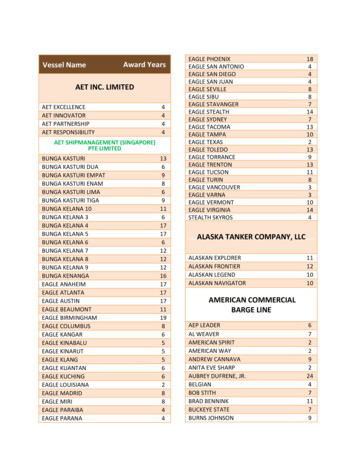
CLARK COUNTY - COMMUNITY DEVELOPMENTBUILDING SAFETYEXAMPLE OF A PRESCRIPTIVE HOUSE PLANBASED ON THE 2015 IRCYLNNO TIOSCEUSROTPSRNUP CONROIOTFATMORNOEFIN MPLASEFFECTIVE UNTIL JULY 2020These plans are provided as a sample for assisting applicants in creating submittal document. These plans are based on the prescriptive criteria set forth in the2015 international residential code (irc)/washington state admendments (wac). If the structure does not meet all of the irc/wac requirements, an engineereddesign conforming to the 2015 international building code (ibc)/wac must be submitted. Plans are also to show compliance with the 2015 Washington State EnergyCode (WSEC) yCode.aspxResidential Structural Design Information:WINDminimum design wind speed 135 mph, exposure BSOIL1,500 psf bearing (default minimum)FROST12" minimumMINIMUM ROOF SNOW DESIGN LOAD25 psf - minimum roof load - non reducible30 psf - ground snow - drift calculations as requiredDESIGN TEMPERATURESSEISMIC ZONED1 for prescriptive/ D for engineering designROOF DRAINAGEPer uniform plumbing code (UPC) 1101.12roof drainage system shall be designed for 2" per hour rainfallFLOOD HAZARDFEMA maps of local areaSHEET TITLE:1Site Plan Example2Floor Plan Example2AWall Bracing Example3Elevations Example4Foundation Plan Example5Roof Framing Plan Example6Roof Plan Example7Cross Section Example8Detail Example9Detail Example10Detail Example11Detail Example12Detail Example13Detail Example14Detail Example15Washington State Energy Code (WSEC) formdownloaded -WSEC-Energy-Plan-Sheet.pdfSupplemental SubmittalsPrescriptive worksheet, glazing schedule andheating system sizing worksheet ency/EnergyCode.aspxAll other loading is per the 2015 international residential code and as adopted by the Washington State Amendments (WAC)Some of the details in this sample packet may bedownloaded ls/15IRC.htmSHEET NUMBERCOVER SHEETCLARK COUNTY - COMMUNITY DEVELOPMENTBUILDING SAFETY1300 FRANKLIN ST., VANCOUVER, WA 986600
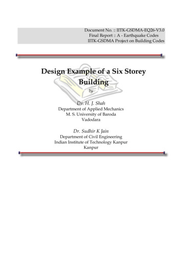
82'-2"less than 5'-0"288288PL1 hr on the underside see tableR302.1(1) footnote a,bless than 2'-0"32'-0"06'-0"10'-4"29projectionsnot permittedroof vents noopenings in roofwhere less than 5'from PLSHOW CONTOURS LINE ONTHE PLAN2x blockingY NLNO TIOSCEUSROTPSRNUP CONROIOTFATMORNOEFIN MPLASCOVEREDPATIO02958'-8"112x faciaExterior finishNOTES:1. Penetrations in walls less than 5'-0" fromproperty line shall comply with R302.4.Exception: foundation vents installed per codeare permitted.2. Garages less than 3'-0" from a dwelling on thesame lot shall be separated as required byR302.65'-0"0290Table R302.1(1) Exterior Walls WAC Non-sprinklered22'-0"15'-5"exterior wall element2929029COVEREDPATIO06'-0"10'-0"one-hour wall required if lessthan 5'-0" from propertyline-5/8" type 'x' gypsumboard each side22'-0"110'-5"38'-0"HOUSEexterior wall elementminimum fire-resistance ratingminimum fireseparationdistance(fire-resistance rated)1-hour tested in accordance withASTM E119 or UL 263 withexposure from both sides 5'-0"(not fire-resistance rated)0 hoursNot allowedN/A(fire-resistance rated)1 hour on the underside (a,b)(not fire-resistance rated)0 hours 2'-0" 2'-0" to 5'-0" 5'-0"Not allowedN/A 3'-0"25% maximum of wall area perstory0 hours3'-0"unlimited0 hours5'-0"Allcomply with section R302.4 3'-0"Allnone required3'-0"40'-6"34'-6" WATER LINEWallsProjectionsDRIVEWAYOpenings in walls28882830'-0"FRONTSTREETCONTACT ZONING REGARDING THE IDE A SEPARATE PLAN FOR PLANNING REVIEW.CONTACT THE PERMIT CENTER FOR ITEMS REQUIREDTO BE SHOWN ON THE PLOT PLANSmetal gutterPARCEL NUMBER:LOT AREA:HOUSE AREA:GARAGE AREA:COVERED PATIO AREA:COVERED ENTRY:TOTAL BUILDING:% OF LOT COVERAGE:DRIVEWAY AREA:DRIVEWAY AND BUILDING AREA:CL 5'-0"Table R302.1(1) footnote:a. Roof eave fire-resistance rating shall be permitted to be reduced to 0 hours on the underside of the eave if fireblocking is provided from the wall top plate to the underside of the roof sheathing.b. Roof eave fire-resistance rating shall be permitted to be reduced to 0 hours on the underside of the eaveprovided no gable vent openings are installed.11PROPERTY LINE PROTECTION IRC R302.1FR-6SCALE: NTSSHEET NUMBERSITE PLAN EXAMPLESCALE 1" 50'CLARK COUNTY - COMMUNITY DEVELOPMENTBUILDING SAFETY1300 FRANKLIN ST., VANCOUVER, WA 986601
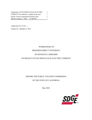
patio cover, see detail1/14 AND 2/1417LEGEND2767'-2"SMOKE 5040 SL. E.SL.W3'-0".3040.WSL403040SL.W.05068 SL.G.DRSL.W7'-4-1/2" HT.4036 SL.W.Y NLNO TIOSCEUSROTPSRNUP CONROIOTFATMORNOEFIN MPLASKITCHEN13'-2"FAMILY ROOM3'-10"8'-4"vaulted ceiling2868 H.C.SDCMSDBATH50 cfmFurn.W.H.3068 20 MIN.DOOR OR 13/8" S.C.213PORCH5/8" Type "X"gyp.board @ ceiling ifhabitable space isaboveBEDROOM #3concrete slab3,000 psi5040 SL. W.emergencyegress44'-0"3068OFFICENo closet6040 SL. W.2468 H.C.3'-10"9'-5"BEDROOM #22.R314.3 Smoke Alarm LocationsSmoke alarms shall not be installed in thefollowing locations unless this wouldprevent placement of a smoke alarm in alocation required by Section R314.3.Less than 3 feet horizontally from thedoor or opening of a bathroom thatcontains a bathtub or shower.Ionization smoke alarms shall not beinstalled less than 20 feet horizontallyfrom a permanently installed cookingappliance.Ionization smoke alarms with analarm-silencing switch shall not beinstalled less than 10 feet horizontallyfrom a permanently installed cookingappliance.GARAGEattic access22"x30" min.unobstructedheadroom 30"5040 SL. W.emergencyegress5'-5"8070 O.H. DOORS11'-4"provide headerdetailsprovide headerdetails2'-9"R315.1 Carbon Monoxide AlarmsAn approved carbon monoxide alarm shallbe installed outside of each separatesleeping area in the immediate vicinity ofthe bedroom(s)DW4'-0"2'-8"2'-6"30682868 H.C.9'-3"68262868 H.C.LAUNDRY50 cfm10'-2"3'-9"68crawl spaceaccess18"x24" min.5'-10"263'-7"10'-5"1.2668SD2'-0" Roof Overhang-typ22'-0"SDCLOSET15'-6"GENERAL NOTES:10'-0"Ref.BATH50 cfm1,796 square feet484 square feet154 square feet2,434 square feet22'-0"22'-6"7'-5"ResidenceGaragePatio coverTotal areaDINING AREAM.Closet38'-0"BUILDING AREA100 cfmM. BEDROOM5'-1"SD/CM30Install gas fire insertper manufacture listing37SD8'-6"6040 SL. EET NUMBERFLOOR PLAN EXAMPLESCALE 14" 1'-0"CLARK COUNTY - COMMUNITY DEVELOPMENTBUILDING SAFETY1300 FRANKLIN ST., VANCOUVER, WA 986602
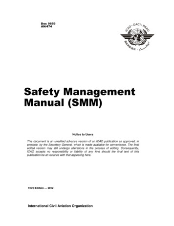
BWL EBWL DBWL CBWL BBWL ALEGEND4'-0"max frombraced wallline174'-0" INTERIOR BRACE PANEL4'-0WSP2'-8"ABW2'-8"ABW2'-8" ABW ALTERNATE BRACEDWALL4'-0"WSP7'-6"10'-0" max tobraced wall panelHOLD DOWN194'-0"Interiorbraced panel seedetail 1/10, typIntermittent Bracing MethodsDINING AREAM. BEDROOMFAMILY ROOMRef.35'-0" max. used once not to exceed 900 SF per table R602.10.1.3CLOSETLAUNDRYSee WSP woodstructural panelGB Gypsum boardInterior & exteriorcan not be usedwith cont.sheathing methodABW Alternatebraced wall panelmin. 2'-8"PFH portal framewith hold-downsMin. thicknesssheathing0'-0 3/8"FastnersSpacingExt. 6d commonInt. 6d common6" edges, 12" field6" edges, 12 field7" edges, 7" fieldHold downs force0'-0 1/2"1 1 2" galvanizedroofing nail; staplegalvanized0'-0 3/8"One story 8d6" edges, 12" field (2) 1,800 poundsFirst of two stories 4" edges, 12" field (2) 3,000 pounds8d common0'-0 3/8"8d common orgalvanized3" in all framing(studs, blockingand sills) typ.(2) 3,500 pounds4'-0"WSPOFFICENo closetD4'-0"WSP4'-0"Interiorbraced panel4'-0"Interiorbraced panelBATHMethods, Material3068M.Closet68BWL 0" Max between braced wall panelY NLNO TIOSCEUSROTPSRNUP CONROIOTFATMORNOEFIN MPLASBracing Wall Methodsreferences table R602.3 (1), R602.3(3), R602.10.4, R602.10.6.1KITCHEN264'-0"WSPNo greater than 25'-0" between BWL Brace Wall LinesBWL 1374'-0" WSP WOOD STRUCTURALPANEL27hold downsee detail29GARAGEBATH4'-0"WSP24" of wall panelfor no hold downdevice. See d panelBEDROOM #34'-0"WSPBWL 34'-0"max. frombracedwallline4'-0"WSPBEDROOM #22'-0"PFH2'-0" -18'-0" spanbetween PFHsee detail 1/8182'-0"PFH18SHEET NUMBERWALL BRACING EXAMPLESCALE 14" 1'-0"CLARK COUNTY - COMMUNITY DEVELOPMENTBUILDING SAFETY1300 FRANKLIN ST., VANCOUVER, WA 986602A
General Elevation Notes:1.Exterior Headers shall be insulated with a minimumof R-10 Insulation.Double 2x Header Sandwiched between or4x Header in 6x Wall or provide a component analysis.8'-0"2. Flashing Requirements:a. Galvanized flashing required above belly bands,window and door trim, decks and all other similar projections.b. Windows are required to be installed, properly flashed,and inspected prior to cover.c. Request flashing under miscellaneous inspection, IVR code 420.d.3. Window Fall Protection - Window Height R312.2.1a. 6' above grade or the surface belowb.c. Shall be fixed or have openings that do not allow theYLFRONT ELEVATIONNNO TIOSCEUSROTPSRNUP CONROIO RIGHT ELEVATIONLEFT ELEVATION TFATMORNOEFIN MPLASException:a.b. Window fall prevention devicesc. Window opening controls per R312.2.2128128125128'-0"6REARELEVATIONS*APPLICANT TO PROVIDE ELEVATIONS AT 14" 1'-0"SHEET NUMBERELEVATION SAMPLE ONLY*SCALE 14" 1'-0"CLARK COUNTY - COMMUNITY DEVELOPMENTBUILDING SAFETY1300 FRANKLIN ST., VANCOUVER, WA 986603
2'-8"3'-0"1727Patio cover footingsee " ABWsee detail283'-0"5'-9"3'-0"16"x24" throughwall access, typ.1101"22'-522x joist pertable ircr502.3.1(2) seedetail 1/12footing neededfor joist span1'-0"continuousfooting requirefor braced wallpanelrequirementssix mil 0.0006" thick blackpolyethylene or approvedequal with 6" min. jointsextended to thefoundation wall44'-0"38'-0"37All interior bracedwall panels in buildingslocated in seismic d1with plan dimensionsgreater than 50'-0" shallbe supportedby continuous footings.15'-612"1.Foundation access required 18"x24" through floor &openings through perimeter shall be 16"x24"-IRC 408.32.Concrete to be 3,000 psi for foundation walls, exteriorwalls and other vertical concrete work exposed to theweather and for concrete slabs of garage floors. Concreteto be 2,500 psi for foundations not exposed to concrete.see the 2015 IRC table R402.2.3.Exterior footings-min. 12" depth4.Foundation ventilation shall be one sq.ft. for every 300sq.ft.- one vent opening shall be within 3' of every cornerper the 2015 IRC/WAC R408.2Y NLNO TIOSCEUSROTPSRNUP CONROIOTFATMORNOEFIN MPLASInterior bracedpanel see detailContinuousfooting forseismicdesigncatergory D122'-0"The ends of eachjoist, beam or girder shallhave not less than 1-1/2" ofbearing on wood and not lessthan 3" on concrete. seedetail113GENERAL NOTES:9'-10"22'-0"2'-8" ABWsee detail 2/8, typ.CONCRETE SLAB3,000 PSI5.Provide radon ventilation see details 1/11 and 2/116.R502.6 bearing.the ends of each joist, beam or girder shall have not lessthan 1.5 inches of bearing on wood or metal and not lessthan 3 inches on masonry or concrete except wheresupported on a 1-inch by 4-inch ribbon strip and nailed tothe adjacent stud or by the use of approvedjoisthangers. the bearing on masonry or concrete shall bedirect, or a sill plate of 2-inch-minimumnominalthickness shall be provided under the joist, beam orgirder.7.General storm drain code requirements:low point drain with backwater valve to slope min 2%away to an approved discharge location.Rain drain piping to be dwv-schedule 40, pvc, or abs.engineered drainage systems must be followed and postedfor inspections.8.R502.7 Lateral Restraint (Blocking) at supportsJoists shall be supported laterally at the ends by full-depthattachment to a full depth header, band or rim joist, or toan adjoin stud or shall be otherwise provided with lateralsupport to prevent rotation.*In Seismic Design Categories D1, lateral restraintshall be provided at each intermediate support.*FOUNDATION VENTS, TYP.1680 SF/300 SF X 144 INCH SQUARESF/73 INCH SQUARE VENT 11 VENTS REQUIREDFooting size1 and 2 story with crawl space 12x6At least one vent shallbe placed within 3'-0"of each corner ofthe building.Portal frame withhold-downs FOUNDATION EXAMPLE PLANSCALE 14" 1'-0"8'-3"1'-6"2'-0"PLANCLARK COUNTY - COMMUNITY DEVELOPMENTBUILDING SAFETY1300 FRANKLIN ST., VANCOUVER, WA 98660SHEET NUMBER4
Roof trusses or rafters2x6 solid blocking2x6 #2 D.F. raftersProvide beam calculations8d @ 4" o.c.roof sheathing(2) 16dnails2x6 #2 D.F. raftersProvide beam calculations*4x8*4x8*4x6*4x6(5) 10dmin.*4x6*4x6Y NLNO TIOSCEUSROTPSRNUP CONROIOTFATMORNOEFIN MPLAS(2) 16dnails*4x82x4 blocking when thebracing is 8'-0" orgreater in length*4x62x4 studs at 24" o.c. orgable end assembly w/2x4 backing or providebracing engineering bytruss manuf.2x6 diagonalbracing@ 72" o.c.15PROVIDE ENGINEERED TRUSSES @ 24" O.C.11solid blocking for 2 x4runner158d on 6" o.c. min. uno*4x8*4x12 beamSimpson A35 orequal @ 24" o.c.GIRDER TRUSSSSGGIRDERTRUIRDERTRUSS*4x6engineered trusses at 24" o.c.*4x6*4x6 HDR *4x6 HDRPair of simpsonGBC or equal eachside of bracing*4x6GIRDER TRUSSER*SIZE ALL HEADERS PER ACTUALSUBMITTED PROJECT, TYP.GIRDRESIDENTIAL CONSTRUCTION GUIDE 9/13*4x12 hdr*4x12 hdrSSUTRTRUERSSDIRGABLE END BRACINGSCALE: NTSG15SHEET NUMBERROOF FRAMING PLAN EXAMPLESCALE 1/8" 1'-0"CLARK COUNTY - COMMUNITY DEVELOPMENTBUILDING SAFETY1300 FRANKLIN ST., VANCOUVER, WA 986605
16Engineered trusses from themanufacturer required at the time ofsubmittalDownspout - typicalto approve drainageverify countyrequirements12"8 in 12cdx plywood orwaffer board lightroof covering over15#5 in 125 in 12Insulation baffleRidge ventR-49 insulation8 in 12Y NLNO TIOSCEUSROTPSRNUP CONROIOTFATMORNOEFIN on h2.5 connectoror approved equal eachtruss4 in 12Ridge ventGutter and downspoutsto approved drainage(see permit specialist)Provide adequateroof ventilation perR806.1R-38 insulationInsulation baffle2x4 blockingw/vent holes6 in 12126 in 1252" dia. vent holes262x10resawnfacia6 in 12Gutter - typical6 in 12TYPICAL EAVE DETAILSCALE:1/2" 1'-0"6 in 1226Ridge vent6 in 122x6 raftersGlu-lam beamsee framing planprovide calculations16ROOF PLANSCALE:1/8" 1'-0"ROOF VENTILATION16EAVE DETAIL @ BAY WINDOWSCALE:1/2" 1'-0"Net free ventilation required 1/150of roof area -using exeception1/300 of roof area provide using 1/2 of required (1796/300) 6.0 s.f.at eave and 1/2 over 3'above eaveSHEET NUMBERROOF PLAN EXAMPLESCALE 1/8" 1'-0"CLARK COUNTY - COMMUNITY DEVELOPMENTBUILDING SAFETY1300 FRANKLIN ST., VANCOUVER, WA 986606
TYPICAL ROOF CONSTRUCTIONCOMPOSITION ASPHALTSHINGLES15# INTERWOVEN FELT716" O.S.B SHEATHINGENGINEERED TRUSSES @ 24"O.C.R-49 BLOWN INSULATIONSHEETROCK121258'-0"Provide beam calculationMASTERBEDROOM8'-0"17Select bearing@ stem wallsee optionson sheetCLOSETCRAWL SPACE18" min from grade to beamw/ 6" mil black vapor barrierR-38 floor insulation11337CLOSETBEDROOMCROSS SECTIONSCALE: 1/4" 1'-0"MASTERBATHROOM112Y NLNO TIOSCEUSROTPSRNUP CONROIOTFATMORNOEFIN MPLAS6TYPICAL EXTERIOR WALLSSIDING716" O.S.B. SHEATHINGWEATHER BARRIER2x6 STUDS @ 16" O.C.R-21 BATT INSULATIONSHEETROCK8'-0"2x6 rafters withR-38 blowninsulationTYPICAL ROOF CONSTRUCTIONCOMPOSITION ASPHALTSHINGLES15# INTERWOVEN FELT716" O.S.B SHEATHINGENGINEERED TRUSSES @ 24"O.C.R-49 BLOWN INSULATIONSHEETROCK27TYPICAL ROOF CONSTRUCTIONCOMPOSITION ASPHALTSHINGLES15# INTERWOVEN FELT716" O.S.B SHEATHINGENGINEERED TRUSSES @ 24"O.C.R-49 BLOWN INSULATIONSHEETROCKFAMILY ROOMContinuous footingunder interiorbraced panel, typOFFICEKITCHENLAUNDRYLAUNDRY126GARAGECROSS SECTIONSCALE: 1/4" 1'-0"312212CROSS SECTIONSCALE: 1/4" 1'-0"*APPLICANT TO PROVIDE SECTIONS AT 14" 1'-0"SHEET NUMBERCROSS SECTION EXAMPLE ONLYSCALE 14" 1'-0"CLARK COUNTY - COMMUNITY DEVELOPMENTBUILDING SAFETY1300 FRANKLIN ST., VANCOUVER, WA 986607
header extent double portal frame (two braced walls)Simpson H2.5 or equaleach truss or rafter2' to 18' openingtop platesmin 3" x 11-1/4" netheader1/2" plywood w/10dnails @ 6" o.c. edges &12"o.c. field code min.3/8" plywood w/8d @ 6"o.c. edges & 12" fieldTable R602.3(1)SIMPSON ST6236 strap or equivalent onY NLNO TIOSCEUSROTPSRNUP CONROIOTFATMORNOEFIN MPLASeach side of opening opposite sidesheathingminimum 2x4 framingtyp.or 2x6 as required2-2x4 blocks at panel splicethat shall occur within24" of midspan, if needed.10'-0" MAX.minimum 3 8" cdx or 716" OSB sheathingone side for one story, both side for twostory nailed with 8d common or galvanized@ 3" o.c. and a 3" grid pattern in headerabove panels10'-0" max.fasten top plate to header with tworows of (6) 16D sinker nails at 3'-0" (typ)double top plates R602.3.2blocking at plywoodsplice2'-8" MIN.double studs min. nailed@ 6" o.c. w/ 16d nailsTable R602.3(1)min. 1800 lb. upliftcapacity holdownsimpson HDU2 orapproved equalSTHD14 with 8" Stem wallFoundation Anchorage R403.1.6(2) 12" dia. x10" anchor boltextended 7" min. @ 6'-0" o.c. w/3"x3"x14" plate washers-R602.11.1subfloormudsillSimpson SSTB16 or equal(2)minimum 12" enbedment intoconcrete12"6" min58" x12" anchor bolt w/3"x3" 1 4" plate washer(R403.1.6)#4 rebar 14" embedmentinto stem w/hooks (typ)#4 rebar, one 3"-4" clearand one within 12" of topof concrete wall8"16"8"#4 vert @ 48" o.c. w/min. 14" entensioninto stem wall atsplices. Min. 6" hook12" MIN.pressure treated platemin. reinforcing of foundation,one #4 horizontal bar topand bottom, lap bars 15" min.3"-4"clear12" x12" continuous footing, min.2500 PSI concrete with (2) #4 reinforcingsteel bars. A turned down slab shall be permitted@ door openings.minimum width 16" for one story, 24" for first level of two story18PORTAL FRAME with HOLD-DOWNS (DOUBLE) R602.10.6.2SW-16DSCALE: NTS28ALTERNATE BRACED WALL PANEL (ABW) R602.10.6.1SW-32-1BSCALE: NTSSHEET NUMBERTYPICAL DETAILSCLARK COUNTY - COMMUNITY DEVELOPMENTBUILDING SAFETY1300 FRANKLIN ST., VANCOUVER, WA 986608
double top plate w/ min. 24" lap atsplice R602.3.2nail roof sheathing tobird blocks w/8d @6"oc at braced panel24" for braced walllines sheathed withwood structural panelNOTESoverlapped top platesat intersecting wallsR602.10.2.2.1#1Min. 24" wide panelfor WSP, CS-WSP,CS-G or CS-PF isapplied to each sideof the building noholdown required ifmin. 48" BP beginswithin 10 feet ofcorner.2.Max. 10'-0"2x studs @16" oc maxwith structuralsheathing see tablebelow for thickness1.Y NLNO TIOSCEUSROTPSRNUP CONROIOTFATMORNOEFIN MPLASSee table below for edgeand field nailing patternOpeningnail min. 2x sill platewith 16d @ 6" oc1 18" subfloor3.4.5.6.All vertical panel jointsshall occur over, and befastened to common studsR602.10.10All horizontal joints shalloccur over, and be fastenedto common blocking ofminimum 1 1 2" nominalthickness.See R602.10.2.2.1 forbraced wall panels locations.Panel method see table below.For masonry stem wall seeR602.10.9 #3.Clark County is in SeismicDesign D1.Pressure treated 2xplate2'-0"8'-0" MAXNo hold down require10'-0" MAXBRACED WALL LINES AT THE CORNERS IRC FIGURE R602.10.7SW-48-C-1SCALE: NTS19R602.10.2.2.1#2Min. 48" brace wallThe end of each bracedwall panel closest tothe end of the bracedwall line shall have an1,800 lb. SimpsonHDU2 or similiarhold-down devicefastened to the stud atthe edge of the bracedwall panels closest tothe corner and to thefoundation or framing.no min.distance atcornerFoundation Anchorage R403.1.612" dia. x10" anchor bolt extended 7" min.@ 6'-0" o.c. w/ 3"x3"x14" platewashers-R602.11.139MIN 48" CONTINOUSLY SHEATHED WOOD STRUCTURAL PANEL (WSP) IRC R602.10.2BWP-48SCALE: NTSOpeningHold-downSimpson HDU2 withSSTB24 or equal10'-0" MAX.48" FIRST BRACEDWALL PANELBraced panel w/hold down devices2'-0" corner is notrequired29BRACED WALL LINES AT THE CORNERS IRC R602.10.7SW-48-C-2SCALE: NTSSHEET NUMBERTYPICAL DETAILSCLARK COUNTY - COMMUNITY DEVELOPMENTBUILDING SAFETY1300 FRANKLIN ST., VANCOUVER, WA 986609
(2) 2x8 blocking nailedto top plate @ 6" o.c.engineered trussesY NLNO TIOSCEUSROTPSRNUP CONROIOTFATMORNOEFIN MPLASA35 each side of each truss5d cooler nails@ 6" o.c. each sideTyp.10'-0" maximum16d nails @ 6" o.c.double top plates R602.3.2NOTE: BRACED WALL PANELSBraced wall panelper planR302.11 Fireblockingall panel edges1 18" subfloor w/10d @6" o.c. edges &12" o.c. fieldsprovide solid blocking under braced panel.Attach between joists with approvedhangers. Nail sheathing to each blockwith min. 3-10d nails Nail panel sole platew/ 16d nails @ 16" o.c. Table R602.3(1)Nail blocking to lower brace panelmin. (3) 16d nails10"Foundation AnchorageR403.1.6.112" dia. x10" anchorbolt extended7" min. @ 6'-0" o.c.w/ 3"x3"x14" platewashers-R602.11.1WSP 4'-0" panel of min. 83" cdx plywood w/6dnails @ 6" o.c. edges & 12" o.c. field -TableR602.3(3).Alternate: GB 8'-0" panel one side or 4'-0"panel each side of 12" gypsum board-studsspaced max. 24" o.c. and nailed at 7" o.c edge& field. w/5d cooler nails-Table R702.3.5.NOTE:R403.1.2- all requiredinterior braced wall panelsshall be supported onfootings at intervals notexceeding 50'-0"1101'-0"Interior Braced Wall Panels(w/joists or rafters perpendicular to panels)INTERIOR BRACED WALL - 48"SCALE: NTSFRM-25SHEET NUMBERTYPICAL DETAILSCLARK COUNTY - COMMUNITY DEVELOPMENTBUILDING SAFETY1300 FRANKLIN ST., VANCOUVER, WA 9866010
Vent Pipe min. 10'-0" away from any windowor other opening into conditioned spaces ofthe building that is less than 2' below theexhaust point and 10' -0" from any window oropening in adjoining or adjacent buildingsmin. 3" diam. Schedule 40 ABS, DWV PVC orother UPC approved gas tight vent pipe with "T"fitting12" min.above roof6-mil visqueen(black) or equalsoil-gas retardermin. lap 12"all punctures or tears in the retardershall be sealed with mastic or otherapproved materialelectrical power sourceto provide for futurevent fan/alarm perAF 103.12Y NLNO TIOSCEUSROTPSRNUP CONROIOTFATMORNOEFIN MPLASvent pipe to be accessible toprovide for future fan installationper AF 103.8All exposed and visible interior radonvent radon vent pipes shall be identifiedwith at least one label each floor and inaccessible attics. The label shall read"Radon Reduction System" AF 103.9Radon Vent Pipe @ Crawl Spaceseal visqueen at pipe w/polyurethene sealersecure w/ mechanicalfastenersmin. 3" diam. Schedule 40 ABS, DWV PVC orothe UPC approved gas tight vent pipe with "T"fitting6-mil visqueen(black) or equalsoil-gas retardermin. lap 12"3" or 4" vent pipeper AF103.5.31/4"/Ft. slopefor drainageopenings, cracks,construction joints tobe sealed withpolyurethane caulkingper AF103.4.24" uniform layer of cleanaggregate withoutscreenings - 1/4" to 2"See AF 103.23" or 4" vent pipe ABS or DWV PVCwith T fitting per AF103.6.1pipe must be located withina warm interior wallAll penetrations sealedwith caulking- AF 103.4.2Vent pipe drainage perAF 103.76-mil polyethylene soil gas retarderin crawl space - lapped min. 12" at jointsand shall extend to all foundation wallsper AF 103.5.2NOTE:NOTE: Additions to existing building, were a newslab is poured or a new crawlspace is beingconstructed with living space above, radonmitigation is required.1. Install radon vent pipes per UPC (Chapter 7 Drain piping),for materials, fitting & installation requirements2. Multiple vent pipes per AF 103.5.2.3. Combination basement and crawl shall have separatevent pipes in each area per AF 103.10.Radon Vent Pipe @ Slabaggregate or other permeablematerial min. 4" thick-see AF 103.2soil gas retarder placed on topof gas-permeable layer prior tocasting the slab per AF 103.3Radon Requirements at slab and crawl space111RADON REQUIREMENTS AF 103MSC-60SCALE: NTS211RADON REQUIREMENTS AF 103MSC-61SCALE: NTSSHEET NUMBERTYPICAL DETAILSCLARK COUNTY - COMMUNITY DEVELOPMENTBUILDING SAFETY1300 FRANKLIN ST., VANCOUVER, WA 9866011
Solid blocking at bearing wallfastened to top plateof pony wall 8d box (2 12" x .113")@ 4" o.c. Per Table R602.3(1)2x pressure treated plate w/ 12" dia. x 10"anchor bolts at 6'-0" o.c. maximum12" from ends and splicesw/ 3"x3"x14" plate washerscaulk2x wall see wallsee detail 3/12Min. R-30 insulation see the 2015 WSECTable R402.1.1 and Table 406.2 for theenergy credit requirement.# 4 rebar horizontalcontinous top andbottom12" min.6"approved hanger6" mil (black) visqueenmin 12" lapper #4 cont. rebar per IRC 403.1.3Detail applicable up to twofloors and one roof load# 4 vert. @ max. 48" o.cw/min. 14" extensioninto stem wall with 6"hook-detail R403.1.3.1Gravel or crushed stone drainsshall extend not less than 1 footbeyond the outside edge of the footingNOTE: unobstructed16"x24" under floorareaway is required to all areasof the crawl space.12"21212" o.c.10'-9"14'-2"18'-0"20'-11"16" o.c.9'-9"12'-9"15'-7"18'-1"12"24" o.c.8'-3"10'-5"12'-9"14'-9"16" o.c.1/2"20" o.c.5/8"R-21 insulation at heated areas staple vapor barrier flange to face of studsSee the 2015 WSEC Table R402.1.1 for allinsulation and fenestration requirements bycomponents24" o.c.3/4"NOTES:1.Floor joist to be minimum Douglas Fir #2. Code loading requirements- 40# live and 10# dead. Not forexterior deck see IRC R507 and the deck detail package.2.Minimum spans for subfloor-underlayment see subfloor span table this sheet.3.Minimum concrete strength 2500 psi, lap rebar min. 30" diam. at slices-secure with tie wire.4.Foundation vents required 1sf for each 300 s.f. of under-floor area-distribute approximately equally on atleast two sides. Recommend starting placement within 3' of corners. IRC R408.5.See the fastener schedule IRC Table R602.3(1) for all other connections.112FOUNDATION/FLOOR FRAMINGSCALE: NTScdx plywoodD.F. #2 studs - 2x6's @ 16" o.c. maximum 10'-0" highD.G. w/ single bottom plate and double topplatesTable R503.2.1 Subfloor spansgrade 1POST & BEAM GIRDER CONNECTIONFRM-51SCALE: NTSlap siding on #15 felt or other approvedweather-resistive barrierTable R502.3.1(2)Floor joist2x62x82x102x12min. 12" x 6" wide strip perfooting Table R403.1 (1)P.T. plates w/anchor bolts18" min.floor joist(see tablefor spans)2% slope6"2" base of washed grave orcrushed rock not lessthan one sieve sizelarger than the perforationsand cover with not less than6" of the same materialIRC 405.1Y NLNO TIOSCEUSROTPSRNUP CONROIOTFATMORNOEFIN MPLAS2x pony wall18" clear8"min.foundation ventsrequiredPerforated drains shall besurrounded withan approvedfilter membraneIRC 405.12x joists fastened to top plate of ponywall with 2 each side 4-8d box (2 12 "x0.113")12"312gypsum wall boardEXTERIOR WALLSCALE: NTSFRM-51RESIDENTIAL CONSTRUCTION GUIDE 5/13SHEET NUMBERTYPICAL DETAILSCLARK COUNTY - COMMUNITY DEVELOPMENTBUILDING SAFETY1300 FRANKLIN ST., VANCOUVER, WA 9866012
2x6 soleplate2x6 soleplateFloor joist, beamor girderper planmin. 2x4 ptsill plateno notching2x6 pt sillplateFloor joist, beamor girderper plansill gasketsill gasket12"ApprovedHanger3" min. bearingR502.6air gap1 8" Stem wallMECHANICAL REQUIREMENTS:MECHANICAL REQUIREMENTS:Hot and cold water pipe insulationrequired per WSEC Sections 503.11& Table 5-12 6" clearance requiredfor gas water heaters from draft hood& 6" to single wall pipe tocombustibles.IFGC 503.12.7 Temperature andpressure relief valve-drain to outsideor other approved location-checkwith jurisdiction.Exhaust to outside- B Vent clearanceto combustibles per manufacture'sListing & 6" for single wall pipe. IFGC503.12.7. Where vent passes throughinsulated assemblies an insulationshield is required. Min. 26 gauge sheetto provide required clearance allaround. Min. 2" above insulation andsecured to prevent displacement perIFGC Section 502.4Expansion tank requiredw/ closed plumbingsystem per UPC Section608.36"See UPC/WAC Sections504.6, 608.3.1 &608.3.5Y NLNO TIOSCEUSROTPSRNUP CONROIOTFATMORNOEFIN MPLAS2 6" Stem wall with approved joist hangerCold water supply linew/ shut offHARDWARE REQUIREMENTS:2x6 soleplateFloor joist, beamor girderper planrim joistper plan2x6 soleplatemin. 2x4 ptsill plate nonotchingFloor joist, beamor girder per planin pocket linersill gasketmin. 2x4 ptsill plate nonotching2x6 soleplateFloor joist, beamor girderper planmin. 2x4 ptsill plate nonotchingsill gasket3" min. bearingR502.65 6" Stem wall with notched floorjoist, beam or girder per plan113Install 2x blocking if tankdoes not have stud behindin as required- See PlanView below4 6" Stem wall with joist liner pocket.As approved by jurisdiction foralternative, materials, design andmethods of constructionNotes:R502.6 Bearing. .The ends of each joist, beam orgirder shall have not less than 3" of bearing onmasonary or concrete or by the use of approvedjoist hangers. The bearing on masonry or concreteshall be direct, or a sill plate of 2" minimumnominal thickness shall be provided under the joist,beam or girder.*Vertical point loads must have fullbearing30" min.joist pocket linerper manufacturer3 Joist bearing on top of 6" stem wallair gapIRC M1307.3 and UPC/WAC507.13 Elevation of ignitionsource. 18" minimumrequired between bottomedge of source of ignitionand finish floor level unlesslisted as flammable vaporignition resistant4" minsill gasket12"Ignition sourcePer manufacturer drill pilothole on centerline of stud,use 1/4"x4" lag w/ washer.See note #4.2x framingNOTE:1.2.3.4.BEARING @ STEM WALL OPTION R502.6FRM-53SCALE: NTSIf wall studs are not properly located to allow adequateanchorage, attach min. 2x4 cross brace to studs with 1/4" x4" lags to studs with 1/4" x 4" lag screw and washers.Attach anchor strap to cross brace with lag screw andwashers. See UPC Section 507.2. Perforated iron strap("plumber's tape") is not an approved method of strappingper UPC 507.2.Per the WSEC, R-10 rigid insulation pad required at allelectric water heater in unheated spaces or on concrete floorwhere a stand is not required.Install water heater tight to wall or 2x4 bracing. See above.UPC/WAC 50
2015 international residential code (irc)/washington state admendments (wac). If the structure does not meet all of the irc/wac requirements, an engineered design conforming to the 2015 international building code (ibc)/wac must be submitted. Plans are also to show compliance with the 2015 Washington State Energy