Transcription
Ice Thermal Storage SystemsGreg HendersonDirector, Global Thermal Storage
Agenda Ice storage basics Ice storage design considerations– Full and partial storage systems– Internal and external melt systems Ice storage installations and applications
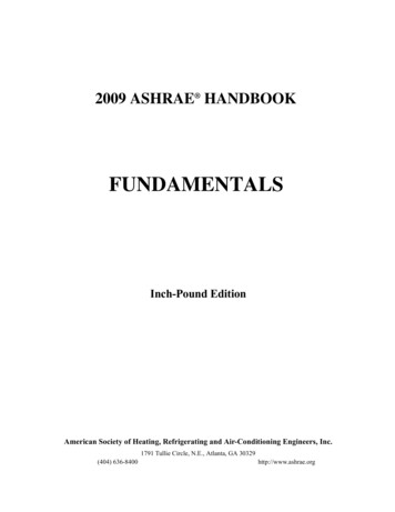
Ice Build on Ice Coil Tube
Ice Build on Ice Coil
What is Ice Storage? Ice Storage is the process of using achiller or refrigeration plant to build iceduring off-peak hours to serve part or all ofthe on-peak cooling requirement
Ice Thermal StorageHow does it work?
Cooling LoadTypical Cooling Load Profile0246810 12 14 16 18 20 22Time of Day
Conventional SystemChillerCooling Load
Ice Storage SystemIce Storage TankChillerCooling Load
Cooling LoadIce Storage CycleIceStorageCycle024IceStorageCycle6810 12 14 16 18 20 22Time of Day
Advantages of Thermal Energy Storage Reduced equipment costs Reduced energy and operating costs Increased flexibility to adapt to changingutility structures and requirements Reduces need for new power plants
Typical Daily Utility Load CurvePower (Megawatts)Total Utility CapacityDemandChargesHigh Timeof DayRates0246810 12 14 16 18 20 22Time of Day
Cooling LoadIce Storage CycleDemandChargesIceStorageCycle024High Timeof DayRates68IceStorageCycle10 12 14 16 18 20 22Time of Day
Electric Generation Fuel Sources% Generation100TheStorageShift8060Comb. turbine 7.0 /kWhDiesel 6.5 /kWhOil-fired steam 3.5 /kWhCombined cycle 3.0 /kWhCoal-fired steam 2.5 /kWh40Nuclear 0.4 /kWh20Hydro-electric 0.2 /kWh0M2468 10 N 14 16 18 20 22Time of Day
Thermal Storage SystemEnvironmental Advantages Require less kWh than conventionalsystems Utilize efficient power and produce fewercarbon dioxide emissions Energy line losses at night are 4% to 5%lower than during the daytimeSource: Source Energy and Environmental Impacts of Thermal Energy Storage, California Energy Commission - February 1996
Advantages of Ice Thermal Storage Reduced equipment costs Reduced energy and operating costs Colder supply water temperature
Advantages of Ice Thermal Storage Reduced equipment costs– Only 60% of chillers and heat rejectionequipment required– Requires only 1/4 to 1/6 of the space requiredfor chilled water storage ( 3Ft3/Ton-Hour)– Requires less chiller plant plan area thaninstantaneous chiller system
30,000 RT Output16,000 RT Heat Rejection
Advantages of Ice Thermal Storage Reduced equipment costs Reduced energy and operating costs Colder supply water temperature
Ice Thermal StorageUses Less Energy During daytime, chillers operate at highersupply temperatures and greater efficiencywhen piped upstream of the ice storage At night, chillers operate when ambienttemperatures are lower Pump and fan energy can be less whencolder system supply temperatures areused
EER of Air Cooled esign PointPre-cooling62025303540455055Leaving CHW95 Air85 Air75 Air* includes heat rejection
EER of Water Cooled Design Point1020253035Pre-cooling40455055Leaving CHW858075* excludes heat rejection
Ice Thermal StorageReduces Operating Costs Reduces air conditioning kW demand byapproximately 40% Reduces air conditioning kWh by up toapproximately 15% Reduces electric utility costs– Large percentage of energy usage is at night– Daytime energy costs 2 to 5 times more thannight time energy
LEED Criteria Sustainable sites (14 possible points)Water efficiency (5 possible points)Materials and resources (13 possible points)Energy and atmosphere (17 possible points)– Ozone depletion– Optimize energy performance Cost based analysis vs. ASHRAE 90.1 Indoor air quality (15 possible points) Innovation & design process (5 possible points)
Advantages of Ice Thermal Storage Reduced equipment costs Reduced energy and operating costs Colder supply water temperature
Advantages ofCold Supply Water Temperature Smaller distribution pumps and piping Reduced pumping power Allows for economical building isolation(indirect interface) with smaller heatexchangers Provides better dehumidification andindoor air quality(IAQ)– 78 F (25.5 C) at 40% RH is more comfortablethan 76 F (24.4 C) at 50% RH Cold air distribution
Burj Dubai Tower Will become world’stallest building at over180 floors Currently at 156 floors 41,600 ton-hours
Taipei 101 Currently the world’stallest building at 101floors 36,400 ton-hours
Taipei 10174th floor41.0 F (5 C)42nd floor39.2 F (4 C)7th & 8th floors37.8 F (3 C)
Factors Favorable forIce Storage Systems Loads are of short duration– Schools Loads occur infrequently– Churches– Sports venues Loads are cyclical in nature– Process or batch cooling
Factors Favorable forIce Storage Systems Loads are not well matched to availabilityof the energy source Energy costs are time-dependent– Time-of-use energy rates Energy supply is limited– Demand charges for peak energy use Utility rebates, tax credits, or othereconomic incentives are provided for theuse of load-shifting equipment
Potential Ice Storage Projects Commercial A/C and industrial– Schools– Hospitals– Office buildings– Internet data centers– Hotels– Airports– Sports venues– Manufacturing plants
Potential Ice Storage Projects Commercial A/C and industrial District cooling– Colleges and universities– Corporate campuses– Hospitals– Convention centers– Sports arenas– Utilities
Ice Thermal Storage SystemsDesign Considerations
Full Storagevs.Partial Storage
Cooling Load (Tons)Batch Cooling or Process LoadProfile0246810 12 14 16 18 20 22Time of Day
Cooling Load (Tons)Full Ice StorageBatch Cooling or Process ApplicationIce Charge024Ice Discharge6810 12 14 16 18 20 22Time of Day
Cooling Load (Tons)Air Conditioning Load Profile0246810 12 14 16 18 20 22Time of Day
Cooling Load (Tons)Full Ice StorageAir Conditioning ApplicationIce Charge024Ice Discharge6810 12 14 16 18 20 22Time of Day
Ice Thermal Storage System DesignFull Ice StorageAdvantages Best suited for short,peak demand periodsand/or high, peakloads Shifts largest electricaldemand that providesthe lowest operatingcost Provides systemstandby capability andoperating flexibilityDisadvantages Largest storagevolume required Larger chiller required Most expensivethermal storage design
Cooling Load (Tons)Partial Ice StorageAir Conditioning ApplicationIce DischargeIce Charge024Chiller6810 12 14 16 18 20 22Time of Day
Cooling Load (Tons)Partial Ice StorageAir Conditioning ApplicationIce DischargeIce Charge024Chiller6810 12 14 16 18 20 22Time of Day
Cooling Load (Tons)Partial Ice StorageAir Conditioning ApplicationIce DischargeIce Charge024Chiller6810 12 14 16 18 20 22Time of Day
Cooling Load (Tons)Ice DischargeIce ChargeChillerBase Chiller0246810 12 14 16 18 20 22Time of Day
Ice Thermal Storage System DesignPartial Ice StorageAdvantages Best suited for longcooling periods Lower first cost due toreduced storagevolume and smallerchiller Provides systemoperating flexibilityDisadvantages Less standbycapability Less electricaldemand shifted to offpeak
Internal Meltvs.External MeltIndirect vs. DirectContact Cooling
Ice Storage System TypesDirect Contact CoolingIndirect Contact Cooling
Ice Thermal StorageIce-on-Coil Technology
Ice Thermal Storage System DesignIce on Coil - Internal MeltIndirectCOLDGLYCOLOUTWARMGLYCOLINICE ON COILMELTING OCCURSFROM INSIDEICE Cold glycol solution is circulated through thecoil to the A/C system Warm glycol solution, circulating through thecoil, is cooled indirectly by the melting iceWARMGLYCOL
Ice Storage DesignInternal Melt (Indirect Contact)
Leaving TemperatureIce Storage DesignInternal Melt Performance*( F)46( C)4464254043833627w/o air agitation3432100102030405060708090100% Ice Meltout*10 hour, constant load
Ice Storage DesignInternal Melt (Indirect Contact)Advantages Simple to design and operate– simple controls for various operating modes– closed, pressurized loop Stable, cold discharge temperatures– 36 F to 38 F (2.2 C to 3.3 C) typical Durable steel construction– 150 to 300 psi (10.3 to 20.7 bar) design pressurerating– tested at 190 to 375 psi (13.1 to 25.8 bar) Flexible layout (modular tanks or vault design)
Ice Storage TankChillerHeat ExchangerOptionalBase ChillerCooling LoadSystem Schematic
Ice Storage DesignInternal Melt (Indirect Contact)Disadvantages Heat exchanger required for chilled waterin building loop Not able to discharge as quickly as directcontact cooling– ice melt limited by flow through coil
Ice Thermal Storage System DesignIce on Coil - External MeltDirectAIRWATEROUTWATERINICE ON COILMELTING OCCURSFROM OUTSIDEICE Ice water is circulated through the icestorage tank to the A/C system Warm return water, circulating through thetank, is cooled via direct contact with the iceWARMWATERREFRIGERANTOR GLYCOL
Ice Storage DesignExternal Melt (Direct Contact)
Leaving TemperatureIce Storage DesignExternal Melt Performance*( F)46( C)44642540438336234132070102030405060708090100% Ice Meltout*10 hour, constant load
External Melt Supply TemperaturesLeaving Water Temp. ( F)40Hours1393837362461235343332100908070605040% Ice Remaining3020100
250 TRGlycol Chiller375 TRWater Chiller42 FCWS250 TRGlycol Chiller250 TRGlycol Chiller(Spare)27.8 FCGR375 TRWater Chiller1500 GPM54 FCWR375 TRWater Chiller(Spare)2000 GPM21.4 FCGS6000 Ton-HoursIce Storage34 FCWS6000 Ton-HoursIce StorageExternal MeltSystem Schematic
Ice Storage DesignExternal Melt (Direct Contact)Advantages Lowest chilled water supply temperatures Quickest discharge capability Eliminates glycol from chilled water loop
Ice Storage DesignExternal Melt (Direct Contact)Disadvantages Chiller with lower temperature capabilitygenerally required Glycol control valves required on largersystems Heat exchanger may require to managestatic head of open system More difficult to monitor amount of ice ininventory
Ice Thermal Storage SystemsExternal Melt vs. Internal MeltExternal Melt Project requires aconstant, cold supplywater temperature of34 F (1 C) or quickdischarge periods Trained operating staffavailable Large savings indistribution piping system Highest energy efficiencyInternal Melt Project does not requirecoldest possible supplytemperature Simpler design andoperation Individual buildings Energy efficiency is lesscritical (extra heattransfer step required)
Ice Thermal Storage SystemsExternal Melt vs. Internal Melt Most air conditioning applications useinternal melt Most process and district cooling systemsuse external melt
Maryknoll Grade SchoolHonolulu, HawaiiBelow-Grade Concrete Tank2,000 Ton-Hours Ice StorageDistrict Cooling Retrofit
Maryland Stadium AuthorityOriole Park at Camden YardsRavens Stadium at CamdenYardsBaltimore, MarylandBuried Concrete Tank13,000 Ton-Hours Ice Storage
Comfort Link District CoolingBaltimore, Maryland USA 32,000 TR peak system capacity21,650 TR chiller capacity75,000 TH ice storage10 miles of distribution system pipingChilled water distributed at 37 F (2.8 C)50 customers– commercial and government office, hospital,data center, hotel, residential, conventioncenter, entertainment and retail space
Comfort Link Plant #2Saratoga and Eutaw StreetsBaltimore, MarylandAbove-Grade Steel Tanks27,000 Ton-Hours Ice Storage
Comfort Link Market Center Chilling Station – Construction (1999)
Comfort Link Market Center Chilling Station – Construction (1999)
Comfort Link Market Center Chilling Station – Construction (1999)
Comfort Link Market Center Chilling Station – Construction (1999)
Comfort Link Market Center Chilling Station – Construction (1999)
Comfort Link Market Center Chilling Station – Construction (1999)
Comfort Link Market Center Chilling Station – Construction (1999)
Comfort Link Market Center Chilling Station – Completion (1999)
Comfort Link District CoolingBaltimore, Maryland USA Operations began in 1996 with traditionalelectric tariff– 10:00 AM to 8:00 PM peak window– Fixed peak demand charge– Time of day energy rates Began purchase of electricity throughindependent suppliers in June, 2002 System flexibility allows daily changes tooperating schedules to minimize spotmarket consumption and capacity charges
Electric Cost Components - Typical UserSRC Current Market Estimate - PJM Mid-Atlantic19%Market - Energy CostMarket - Capacity Cost4%5%Market - Other Costs72%Local Delivery / UtilityCurrent Market Supply Estimate, 1 Year: 85- 88/MWh
Electric Cost Components Energy– Based on prevailing market prices– Daytime energy costs average twice nighttimeenergy costs Capacity– UCAP (generation capacity charge) Highest system load hour on each of 5 highestload days (not customer)– Transmission– More than 60/kW/year
200020PJM ISO Price ( /mW)Comfort Link kWEnergy Cost Operating 037/4/037/5/037/5/037/5/0312:00 AM 6:00 AM 12:00 PM 6:00 PM 12:00 AM 6:00 AM 12:00 PM 6:00 PM 12:00 AM 6:00 AM 12:00 PMChart courtesy of Comfort Link
200020PJM ISO Price ( /mW)Comfort Link kWEnergy Cost Operating 037/4/037/5/037/5/037/5/0312:00 AM 6:00 AM 12:00 PM 6:00 PM 12:00 AM 6:00 AM 12:00 PM 6:00 PM 12:00 AM 6:00 AM 12:00 PMChart courtesy of Comfort Link
200020PJM ISO Price ( /mW)Comfort Link kWEnergy Cost Operating 037/4/037/5/037/5/037/5/0312:00 AM 6:00 AM 12:00 PM 6:00 PM 12:00 AM 6:00 AM 12:00 PM 6:00 PM 12:00 AM 6:00 AM 12:00 PMChart courtesy of Comfort Link
Demand Limiting Operating StrategyTotal System Tons (000)ChillerIce12 mWDemand Shift25201510500 1 2 3 4 5 6 7 8 9 10 11 12 13 14 15 16 17 18 19 20 21 22 23HourJune 27, 2007High of 100 F (37.8 C)Low of 80 F (26.7 C)Chart courtesy of Comfort Link
LoadLevelingOperatingRecordHeat andRecordStrategyLoads(1) 1750 TR chiller out of serviceTotal System Tons (000)Chiller25201510500 1 2 3 4 5 6 7 8 9 10 11 12 13 14 15 16 17 18 19 20 21 22 23HourAugust 8, 2007High of 108 F (42.2 C)Low of 86 F (30.0 C)Chart courtesy of Comfort Link
Load Leveling Operating Strategy(1) 1750 TR chiller out of serviceTotal System Tons (000)ChillerIce6 mWDemand Shift25201510500 1 2 3 4 5 6 7 8 9 10 11 12 13 14 15 16 17 18 19 20 21 22 23HourAugust 8, 2007High of 108 F (42.2 C)Low of 86 F (30.0 C)Chart courtesy of Comfort Link
Demand Limiting Operating StrategyPredicted performance with all chillers in serviceTotal System Tons (000)ChillerIce11 mWDemand Shift25201510500 1 2 3 4 5 6 7 8 9 10 11 12 13 14 15 16 17 18 19 20 21 22 23HourAugust 8, 2007High of 108 F (42.2 C)Low of 86 F (30.0 C)Chart courtesy of Comfort Link
Ice Thermal Storage SystemsGreg HendersonDirector, Global Thermal Storage
Ice Thermal Storage Systems Greg Henderson Director, Global Thermal Storage. Agenda Ice storage basics Ice storage design considerations . Currently the world's tallest building at 101 floors 36,400 ton-hours. 7 th& 8 floors 37.8 F (3 C) 42nd floor 39.2 F (4 C) 74th floor 41.0 F (5 C) Taipei 101.