Transcription
Prostheticsand OrthoticsInternational,1998, 22,54-67Biomechanical evaluation of the Milwaukee braceM . S. W O N G and J. H. E V A N SJockey Club RehabilitationEngineeringCentre, The Hong Kong PolytechnicUniversity,Hong Kong,China.and Moe in 1945. It is commonly used for thenon-operative treatment of the thoracic curve ofadolescent idiopathic scoliosis with moderateseverity (Cobb angle: 25 -45 ). Clinicalexperience with the brace has led to manyimprovements, both in the design of the braceitself and in the manner in which it is used.However, little study had been devoted to therelationship between the forces that the braceelicits, either passively or through muscle action,although it is accepted that these forces are amajor factor in whatever correction is obtained.AbstractAlthough, the history of orthotic treatment foridiopathic scoliosis goes back more than fiftyyears, the mechanism of curve control by spinalorthosis is still controversial. Hypotheticalexplanations have been provided but few, if any,have been tested clinically. This study aims atthe biomechanical evaluation of a spinal orthosis( M i l w a u k e e brace) in order to improveunderstanding about the mechanism of curvescontrol in orthotic movement.From the results of the study, the change of theinterface pressure between the patient's bodyand thoracic pad, and the tension of the thoracicstrap were highly correlated (r 0.84) as patientsperformed different lying postures and dailyactivities. Lying on the thoracic pad is found tohave the highest correctional force a m o n gdifferent lying postures that may be favourablefor preventing curve deterioration.The findings indicate that an increase intension of the thoracic strap will increase theinterface pressure on the thoracic pad and thusincrease the resultant force exerted on thepatient's body by the thoracic pad. Care must betaken as an excessive strap tension will increasediscomfort and restrict body shifting exercises.The results also suggest that in scoliosis withthoracic lordosis, a short outrigger (small pullingangle of the thoracic strap) should be used as itwill decrease the anteriorly directed forcecomponent so as to prevent exaggerating thethoracic lordosis.T h e M i l w a u k e e brace is a mechanicallycomplex device which is different from lowprofile spinal orthoses such as the Boston braceand New York Orthopaedic Hospital orthosiswhich were believed to supply only passiveforces (Winter and Carlson, 1977; Laurnen etal., 1983; Willner 1984; Wynarsky and Schmitz,1990). T h e M i l w a u k e e brace can applylongitudinal as well as transverse forces (Blountand Moe, 1980; Bradford et al., 1987; Winter etal., 1986) The shoulder sling, thoracic pad andlumbar pad of the brace can apply forces ofdifferent magnitudes, in different directions andat different points. The brace may be used tocorrect single, double and triple scoliotic curvesvariously situated (Adriacchi et al., 1976).However, the corrective forces applied to thespine will be limited by the nature of the areason the b o d y ' s surface through which force canbe transmitted. The spine cannot be directlyaccessed by external forces but rather through itscorresponding ribs and soft tissues. Theseforces, applied across specific contact areas,may be sufficient to produce substantial stressand strain within the soft tissues, which canimpair the blood supply and lymphatic drainage.If these interface conditions are prolonged, cellnecrosis will result and may lead to the nThe Milwaukee brace was designed by BlountAll correspondence to be addressed to Mr M . S.Wong, Jockey C u b Rehabilitation Engineering Centre,The H o n g Kong Polytechnic University, Hong Kong,China. Tel: (852)-2766-7680. Fax: (852)-2362-4365.E-mail: R C M S W O N G @ P O L Y U , E D U . H K54
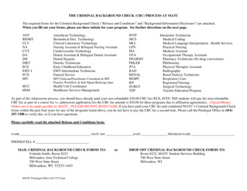
Biomechanicalevaluationulceration. Therefore, the control of the interfacepressure distribution in orthotic treatment is veryimportant especially beneath the thoracic padand pelvic girdle where the pressure is likely tobe highest.A possible method of objectively defining theaction of the brace is to study the forces exertedby the brace on the patient. Knowledge of therange and characteristics of these forces couldthen be used to evaluate the accuracy of fit,efficiency of support and effectiveness of anydesign modification. It could also lead to a betterunderstanding of the mechanisms of correctioninvolved.The study of the forces exerted on thepatient's body by bracing may be accomplishedby measuring the forces in all major bracecomponents such as throat mould, occipitalpads, shoulder ring, uprights, thoracic pad,lumbar pad and hip girdle but the measurementsinvolved for all the above components are verycomplicatedandneedmanybracemodifications, and as a result the brace may betoo greatly modified to allow the patient toperform normal activities. It is better to simplifythe methods of measurement, have the fewestbrace modifications and collect those data ure on the thoracic pad and thetension of the thoracic strap were investigated inthis study. The thoracic strap is used to fit overand exert forces on the thoracic pad. Thevariation of the tension and direction of pull ofthe thoracic strap with have an effect on themagnitude and direction of the correctionalforces exerted on the body by the thoracic pad.These are among the most important variables inobtaining optimum performance from a brace(Andriacchi et al., 1976; Winter and Carlson,1977; Bunch and Patwardhan, 1989).The objectives of this study are to measure thechanges which occur in the interface pressuredistribution and the net correctional force of thethoracic pad on the patient's body by altering theposture, activity, thoracic strap tension andpulling direction of the thoracic strap. Thecorrelation between the change of the thoracicstrap tension and the pressure on the thoracicpad will also be studied.Material and methodsPatient sourceScoliotic patients were selected from thoseof the Milwaukeebrace55attending the Spinal Clinic which is held twice amonth in the Duchess of Kent C h i l d r e n ' sHospital at Sandy Bay, Hong Hong. The patientsattending this clinic were mainly referred fromthe out-patient clinic of the same hospital orfrom doctors in private practice.Each patient had a full clinical evaluationincluding a detailed medical history (patient'sspinal deformity, general health, family historyand maturity status). The physical examinationsincluded anthropometric measurements, rangeof motion of the spine, forward bending test,neurology assessment, cardiorespiratory systemand the secondary sexual characteristics. Allpatients had the following radiographs of thespine: standing anteroposterior, standing lateral,supine anteroposterior and supine bending.From these radiographs, data related to theskeletal maturity, curve pattern and curvemagnitude were obtained.Patient selectioncriteriaThe following criteria were used for selectionof patients as subjects within this study:1. progressive adolescent idiopathic scoliosis(according to Lonstein and Carlson, 1984);2. age 10-14 years;3. Skeletally immature patient (Risser sign 4 orless); and4. Cobb angle ranged from 25 to 4 0 degrees andundergoing orthotic treatment.Methods ofmeasurementThere were two measured parameters, straptension and interface pressure. The measurementmethods were as follows:a) Measurementof thoracicstraptensionA purpose designed buckle force-transducer(Fig. 1) is used to measure the tension in thethoracic strap and may be used in other strapssuch as the shoulder strap. The device is small(35 x 35 x 5mm). The tension in the strap can bemeasured in situ without modification to thebrace or strap. It is simple to install - by taklngout the removable pin and placing the transduceron the thoracic strap then inserting theremovable pin to the original position.With the buckle force-transducer placed onthe strap, the longitudinal tensile force along thestrap generates a bending moment on the centralbeam of the frame. The relationship between thetensile strap force and the amount of moment
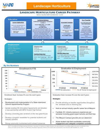
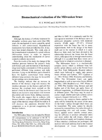
56M. S. Wong and J. H. EvansThe whole recording mechanism of straptension is that the buckle force-transducer firstlytransforms the mechanical signal (tension force)into an electric signal which is amplified by asingle conditioner, and then to a XYt recorder(PM8272, Philips, Netherlands) which recordsthe signal in the form of graph plot. The signalconditioner operates at low voltage (3V) and iselectrically isolated.Fig1 The structure of the purpose designed buckleforce-transducer.generated depends on the off-set from thelongitudinal axis of the strap (Fig. 2). Theamount of moment that deforms the centralbeam is sensed by two stain gauges. The threemetal rods of the buckle transducer form the axisfor thin nylon rollers which help reduce thefriction between the strap and the metal rodduring the loading and unloading. Anotherpurpose of the nylon rollers is to increase theamount of strap off-set which will increase thesensitivity of the transducer without significantchange of the strap length.The buckle force-transducer is fitted over thestrap of the thoracic pad just behind theattachment to the anterior outrigger. This is thebest location for the buckle as it is free fromcontact with the body, thoracic pad andoutrigger. The free length of location for thetransducer is about 35mm.The transducer is connected as a half-bridgedsystem with two strain gauges, each furnished toeither side of the buckle frame. The straingauges of the buckle force-transducer aremanufactured by Tokyo Sokki Kenkyujo Co.,Ltd. and their specifications are - type: FLA- 32 3 , gauge length: 3 m m , gauge resistance:120 0.3Ω and gauge factor (strain - sensitivityfactor): 2.15.An Instron testing machine (Model 1122,Instron Ltd., High W y c o m b e , UK) and a straingauge meter were used in the calibration of thebuckle force-transducer. T h e buckle forcetransducer was placed on a double-layer Dacronstrap. The two ends of the strap were firmlyanchored via special grips to the load cell (tosimulate the condition as in the spinal orthosis).The strap was loaded in tension from 0 to 300 N(normal strap tension estimated to be less than200 N) and then unloaded. The loading andunloading rate was 10mm/min. Hysteresis wasobserved which may be due to the elasticproperties of the Dacron strap, the frictionbetween the strap and buckle transducer,eccentricity in the nylon rollers or the non-rigidframe structure. These adverse factors have beenminimised by pre-conditioning the Dacron strap,using concentric nylon rollers and increasing thebuckle frame rigidity. After the aboveimprovements, the degree of hysteresis has beenreduced to an acceptable level (Fig. 3).Fig. 2. Force diagram of the buckle force-transducer.
Biomechanicalevaluationof the Milwaukeebrace57Fig. 3. Calibration of the improved buckle force-transducer.thoracic pad which was further reinforced by theright posterior upright as the thoracic pad cameinto contact with the posterior upright.The interface pressure (correcting pressure)between the patient's body and the thoracic padwas measured by the Dynamic Pressure Monitor(DPM 2000C) which was manufactured byRaymar Ltd., in England. It uses an electrohydraulic system which can operate at highsampling rate ( 1 Hz for all sensors) unlike otherpneumatic-type pressure monitors, whichoperate at low speed and can only take onesample for each sensor at a time. High samplingrate is required for measuring activities such asbody shifting and deep breathing. Themeasurement range is from 0 to 240 m m H gwhich is adequate for the measurement purpose.The metal neck ring totally embraced the neckbut with enough clearance to permit breathingT h e D y n a m i c Pressure Monitor has twoand physical exercise. T h e left and rightmeasuring matrixes (each covering a total areaposterior uprights were aligned by droppingof 2700 sq m m ) and each has four electroplumb line from the corresponding rivet hole ofhydraulic sensors (each sensor has a diameter ofthe posterior part of the metal neck ring. The two14mm) arranged in a parallelogram shape. Theposterior uprights were 100mm apart(centre-line two matrixesto centre-line)fromon eachTheare arrangedeither other.a horizontalpositioning of the pad depended on the level ofaxis or vertical axis (Figs. 4 and 5) and held inthe scoliotic curve apex. The medial border ofplace with adhesive tape on the free boundariesthe thoracic pad was placed just medial to theon the inner surface of the thoracic pad formedial border of the right posteriorly uprightmeasuring the pressure distribution on differentand was secured in position by two Dacronportions of the thoracic pad. A Macintoshstraps attached posteriorly to the thoracic padcomputer is required to run the software of thewith the other ends attached to the right posteriorD P M 2000C. The collected data can be stored asupright. The thoracic pad could be moved freelydata file or expressed as line plots or histograms.in anterior and posterior directions. The designIn calibrating the Dynamic Pressure Monitor,aimed at giving an anterior-directed force to thethree pieces of equipment are used. These are apatient's trunk though the posterior part of thecalibration chamber, sphygmomanometer andhand pump. The pressure sensors are insertedb) Measurementof pressureon the thoracicpadThe thoracic pad was made of thin aluminiumalloy ( 2 0 2 4 - T 3 : 1.55mm in thickness), thesurface facing the patient's body was coveredwith a soft material (Pelite: 5mm in thickness)and the pad was totally covered with leather(bridle light: 2mm in thickness). The thoracicpad could be bent by bare hands. The bendingrigidity of the thoracic pad would affect thepressure readings, thus two precautions havebeen taken. Firstly, the thoracic pad wascontoured according to the p a t i e n t ' s bodycontour with no
Prosthetics and Orthotics International, 1998, 22, 54-67 Biomechanical evaluation of the Milwaukee brace M. S. WONG and J. H. EVANS Jockey Club Rehabilitation Engineering Centre, The Hong Kong Polytechnic University, Hong Kong, China. Abstract Although, the history of orthotic treatment for idiopathic scoliosis goes back more than fifty years, the mechanism of curve control by spinal orthosis .