Transcription
Predictive Engineering Femap 10.1.1 Composites TutorialModeling Composites withFemap 10.1.1Revised 2010 – All Rights ReservedAn Introduction toThe How’s and Why’sGeorge Laird, Ph.D., P.E.Principal Mechanical EngineerGeorge.Laird@PredictiveEngineering.com
Predictive Engineering Femap 10.1.1 Composites TutorialRevised 2010 – All Rights ReservedTable of ContentsDefining a Laminate Material in Femap . .Femap Layup Editor . . .p Materials Overview . OrthotropicDefining an Orthotropic Material in Femap . .Example 1: Creating a Submarine Laminate Model in Femap . . .Creating the Laminate Material .Defining the Laminate Layup D fi i theDefiningth LaminateL i t PropertyPt .Specifying Material Angles Post Processing the Results Using Plate Elements to Model Honeycomb Core Composites .ppto HoneycombyCompositesp. .Classical Plate Theoryy AppliedThe Nastran PShell Property Card .Using the PShell Property Card for Honeycomb Composites Using Femap to Setup a Honeycomb Panel Example 2: Comparing Different Laminate Modeling Methods . .Materiali l Propertiesi usedd ini theh Examplel Honeycomb Model using Solid Elements with Laminate Face Skins Honeycomb Model using Classical Plate Theory .Honeycomb Model using Laminate Elements Results Summary .Conclusion .345681011121315171819202122232427313435
Predictive Engineering Femap 10.1.1 Composites TutorialRevised 2010 – All Rights ReservedDefining a Laminate Material in FemapTo define a Laminate Material inFemap, 3 specifications must bemade: The Composite Layup that is to beused must be specifiedspecified. TheseLayups are defined using the LayupEditor. A Bond Shear Allowance must alsobe specified. The value representsthe bond strength between the bondedlaminate sheets. This value is used tocalculate a factor of safety againstshear failure between laminatepa e s.panels. A Failure Theory must also bespecified. If Tsai-Wu is specified,then the Tsai-Wu interactioncoefficient must also be specified inth materialthet i l definition.d fi iti
Predictive Engineering Femap 10.1.1 Composites TutorialFemap Layup EditorRevised 2010 – All Rights ReservedThe new layupThleditordit ini FemapFallows for the easy specification oflaminate configurations. This neweditor allows plys to be be editedindividuallyy or collectively.y It alsoallows each ply to be moved aroundin the layup, as well as easy editingof ply thickness and angle.A compute button has also beenadded that allows the user to calculateand display the A, B and D matriceswhich represent the laminatebehavior. These matrices arecalculated and then displayed in themessages window.
Predictive Engineering Femap 10.1.1 Composites TutorialOrthotropic MaterialsOften times Composites can be modeled asOrthotropicp materials. The Nastran Mat8 materialcard can be used to simulate orthotropic behavior.Revised 2010 – All Rights Reserved21Theh abovebiis an examplel off an orthotropichi material.i lThe 1 direction could corresponds to the x directionand the 2 to the y or vise-versa. When deciding whichdirection is the x and which is the y, what is importantis that the chosen convention is adhered to.
Predictive Engineering Femap 10.1.1 Composites TutorialDefining an Orthotropic Material in FemapRevised 2010 – All Rights ReservedFEMAP requires the entry of 5values: 2 Young’s Moduli for the material’sprimary directions. A 1-2 Shear Modulus 2 Transverse Shear Moduli, 1z & 2z The 1-2 Poisson Ratio, the 2-1Poisson Ratio is not required. Thesymmetry of the material stresstensor allows FEMAP to calculate itbased upon E1E1, E2 and v1-2v1-2.There are a number of other valuesthat can be entered depending uponwhat type of analysis is going to becarriedi d out.
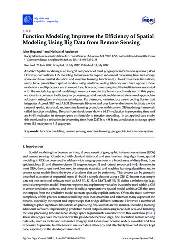
Predictive Engineering Femap 10.1.1 Composites TutorialOne of the more difficult aspects of working with composites isgettingi realistic,li i usablebl materiali l data.dMatt Piatkowskii kki at Heathh Tecnainc. provided an example of a material model they have developed.These values were derived through correlating experimental data withFEA models. Built into this material model are a number ofassumptions: it is only valid for certain shapes and loading schemes.The model works well in pure flex, but does not work well when a lotof shear or twist is imposed on the structure.1) HMS B1-002 TY I-TS2) Graphite TapeSuch limitations and assumptions are very important to quantify. AnFEA model is only as good as the assumptions that go into it.Revised 2010 – All Rights Reserved3) HMS B3-001 TY4 CL1 GR9
Predictive Engineering Femap 10.1.1 Composites TutorialRevised 2010 – All Rights ReservedExample 1: Creating a Submarine LaminateModel in Femap
Predictive Engineering Femap 10.1.1 Composites TutorialRevised 2010 – All Rights ReservedThe model to the right is asection of the submarine modelshown on the previous page.The original model was builtusing plate elements, but in thisexample we will modify it sothat the submarine ‘skin’ is alaminate.The port is composed of solidelements, with an assumedmaterial of steel. The ring ofblue elements around the portare plate elements, whosepurpose it is to simulate a weld.These plate elements are alsoassumed to be steel.
Predictive Engineering Femap 10.1.1 Composites TutorialCreating the Laminate MaterialRevised 2010 – All Rights ReservedThis model will use a singlematerial for the laminate plies.The properties are those of aGraphite/epoxy compositeψ.The Limit Stress/Strain sectioni usedd forisf calculatingl l i failuref ilindexes. There are a number ofindexes Nastran will calculate:Hill, Hoffman, Tsai-Wu, andMaximumiStrain.S i Tsai-Wuirequires a material dependantexperimentally derived value, itis in the material definition thatthishi valuel iis specified.ifi dWe will use Hoffman’s criteria,so this value isn’t necessary forour analysis.ψJones,Robert M. Mechanics of Composite Materials. New York: Hemisphere, 1975. 70.
Predictive Engineering Femap 10.1.1 Composites TutorialDefining the Laminate LayupAfter the orthotropic materialis created,created the Layup Editorcan be used to define how thelaminate plies are situated.Revised 2010 – All Rights ReservedThe laminate that has beendefined on the right consists of7 plys, each 0.2 inches thick.The primary direction of theplies varies by 9090º.This is a fairly simpleconfiguration. Often theindividual plies are differentmaterials, the top and bottom plies being composed of a somewhat tough material while theinner plies are more light-weight. Configurations such as these impart a large area moment ofinertia while remaining light weight.
Predictive Engineering Femap 10.1.1 Composites TutorialDefining the Laminate PropertyWe are now just a short jumpaway from having a laminateproperty defined. Thelaminate definition requires theuser to specify which Layupwill define the the laminate.Revised 2010 – All Rights ReservedThe BondShr Allow also needsto be specified if a bond factorof safety is desired. The valuei arrivedisi d at byb dividingdi idi theh inter-plyil shearh stress byb theh BondShrdSh AllAllow.It is here that the Failure theory is also specified. This example will use Hoffman’s theory.These failure theories produce failure indexes. An index greater than 1 denotes failure. Eachplyl ini theh laminatel iwillill havehan associatedi d failuref ilindex.i dTheTh equationi usedd to calculatel l thehHoffman index is shown below.
Predictive Engineering Femap 10.1.1 Composites TutorialSpecifying Material AnglesRevised 2010 – All Rights ReservedAfter the elements areassigned the laminateproperty, they need to begiven a specified angle thatcorresponds to the primarydirection of the layup. Theabove picture specifies thedirections we are interestedin specifying. The ring oftwo elements around theport are to have anorientation tangent to theedge of the port, while allother elements need to pointin the vertical direction.Going to Modify-UpdateElements-Material Angleallows the user to specify the laminate direction. In the case above, a cylindrical coordinate systemwas created, called Cylindrical 1. Using this coordinate system, the inner ring of elements werepas pointingpg in the theta direction.specified
Predictive Engineering Femap 10.1.1 Composites TutorialRevised 2010 – All Rights ReservedIt is important to ensure that all laminate elementshave an angle specified. Nastran will not run theanalysis if elements are missing an anglespecification. Element normals are also important ifyour laminate model is not symmetric. These must bespecified to ensure that element orientation isconsistent.On the right is an example where a certain portion oflaminate elements have unspecified angles. Oftenfinding where these elements are is a chore. To solvethe problem, I created an API script that searches forthese elements, then highlights and groups them. Thebottom graphic shows this. This API is calledComposites Material Angle Checker, and can bedownloaded from our website After loads and boundary conditions are specified, themodels is ready to process.
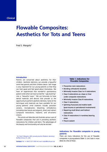
Predictive Engineering Femap 10.1.1 Composites TutorialPost Processing the ResultsFor each element, there are 7 pliesand each of these plies hasassociated data, e.g. stresses,strains,i failuref ilindexes.i dTheh plotl onthe right is that of the maximumfailure index for each element.Revised 2010 – All Rights ReservedIt can be seen that under thisloading condition, the Hoffmanfailure criterion predicts amaximum index of 0.243. Thisvalue is well below 1, and thereforewee can infer that this portion of thevessel is quite safe.It should be noted that this is afailure index, NOT a factor ofsafety. Hoffman’s equation is notlinear, and should not beConstruded to imply that thestructure has a factor of safety of1/0 243 or 4.1.1/0.24341In order to generate a factor of safety, Hoffman’s equation needs to be solved in it’s quadratic form.See Daniel, Isaac M., and Ori Ishai. Engineering Mechanics of Composite Materials. New York: Oxford, 1994. 120-124.
Predictive Engineering Femap 10.1.1 Composites TutorialRevised 2010 – All Rights ReservedThe inter-laminateThi t l i t bondingb difactor of safety is shown on theright. The bonding index see amaximum at the center of theelements This is what we wouldelements.expect to see as predicted byclassical plate / beam theory.There should be zero shear forceon the surfaces and a maximumat the centerline.
Predictive Engineering Femap 10.1.1 Composites TutorialUsing Plate Elements toModel Honeycomb CompositesRevised 2010 – All Rights ReservedNastran and Femap both allow for the useof the PShell property card forhoneycomb composites. This section ofthe tutorial deals with how Classical PlateTheory can be used to define a plateelement which reasonably replicates thebehaviorbeav o ofo a Honeycombo eyco b CoreCo eComposite.
Predictive Engineering Femap 10.1.1 Composites TutorialClassical Plate Theory Applied toHoneycomb CompositesIt iis importantit t tot rememberb thatth t thereth isi one majorjassumption made in classical plate theory withrespect to honeycomb composites; it isassumed that all of the in-plane stresses arecarried byy the facesheets. The followinggrelationships can be derived:Membrane StiffnessEtK 1 ν 2Revised 2010 – All Rights ReservedBending StiffnessEI 'D 1 ν 2T/2DI’ is the bending moment of Inertia per unit width32 d t 1I' d 33 2 2 12If d t, then the following can be assumed:td 2I' 4
Predictive Engineering Femap 10.1.1 Composites TutorialRevised 2010 – All Rights ReservedThe NastranPSHELLProperty Card
Predictive Engineering Femap 10.1.1 Composites TutorialRevised 2010 – All Rights ReservedUsing the PSHELL Card for Honeycomb PanelsPID - PropertyPt IDMID1 - This entry specifies the material number ofthe facesheets.T - The total thickness of the facesheets.MID2 - ThisThi entryt alsol specifiesifi theth materialt i lnumber for the facesheets.12I/T3 – The inertia of the facesheets is enteredhere. If the facesheets are thin, and the core isthick, then it can be assumed that: I TD2/4If the facesheets are relatively thick, then I 2/3 [D/2 T/2]3 – D3/12MID3 – This entry specifies the material number ofthe honeycomb core.Ts – This value is the shear thickness and in the caseof a honeycomb core, is D.NSM – Non Structural Mass must be added to thecard. For a honeycomb core,NSM D rhocoreT/2D
Predictive Engineering Femap 10.1.1 Composites TutorialUsing FEMAP to Setup a Honeycomb PanelTh FEMAP plateThel t propertytdefinition interface is fairlyeasy to use.Revised 2010 – All Rights ReservedThe Thickness of theffacesheetsh t isi enteredt d asusual.The facesheet materialis specified here.The bending stiffness can alsobe entered, with valuesobtained from classicalplate theory equations.The core materialis specifiedhere.Shear thickness, or in the caseof honeycomb panels,D/T can alsoD/T,l beb entered.t dThe mass of the core must alsobe added. This is donethrough the addition ofNonstructural mass.
Predictive Engineering Femap 10.1.1 Composites TutorialExample 2: Comparing Different LaminateModeling MethodsIn this example we will build a honeycombcomposite model in three different ways.1.2.Revised 2010 – All Rights Reserved3.Using solid elements for the core,and laminate elements for the facesheets.Using plate elements, which utilizeclassical plate theory to represent thecore and face sheets all in oneproperty.Using a laminate element which willencompass the face sheets as well asthe core all in one property.We will then compare the pros and cons of each methods, and evaluate the results.The models are simply supported, with a body load of 10 G’s. Each configuration is modeled ashalf symmetric.
Revised 2010 – All Rights ReservedPredictive Engineering Femap 10.1.1 Composites TutorialThe material properties for the face sheets and the core are shown above.The face sheets are graphite composite, while the core is modeled as anisotropic material.material
Predictive Engineering Femap 10.1.1 Composites TutorialHoneycomb Panel Using Solid Elements for theCore and Laminate Elements for the Face SheetsThis fiThifirst modeld l was bbuiltil usingi HexH elementslfor the core, and Laminate elements for theface sheets.Revised 2010 – All Rights ReservedThe Laminate elements are given an offset of0.05 to compensate for their thickness.
Predictive Engineering Femap 10.1.1 Composites TutorialRevised 2010 – All Rights ReservedThe Layup for the face sheets is shownon the right. The face sheets are 0.1inches thick being composed of 8 plys,each 0.0125 inches thick. These plys areoriented so as to perform in an isotropicmanner.
Revised 2010 – All Rights ReservedPredictive Engineering Femap 10.1.1 Composites TutorialDeflection results for the solid / laminate model are shown above. The peakdeflection is -0.0139 inches.
Predictive Engineering Femap 10.1.1 Composites TutorialRevised 2010 – All Rights ReservedHoneycomb Panel Using Classical Plate Theory toRepresent the Core and Skins in One PropertyIn this model, plate elements will be used to simulate the behavior of the honeycomb panel. Theequations from classical plate theory given on pages 18-21 are used to modify the behavior of theplate element.
Predictive Engineering Femap 10.1.1 Composites TutorialThe Layup for the face sheets isshown on the right. For this model,we would like to generate a materialwith equivalent isotropic properties.Luckily, Femap provides a greatnew option to do this. There is anew option in the Layup Editorcalled Compute.If this is selected, Femap willcompute all the composite propertiesforo thee layup,ayup, computingco pu g in-planepa eproperties, as well as the A, B and Dmatrices.Revised 2010 – All Rights Reserved8 Plies - Total Thickness 0.1In-Plane PropertiesEx 10556320. Ey 10556320. Gxy 3990317.NUxy 0.322742 NUyx 0.322742p 0. Alphayp y 0. Alphaxypy 0.AlphaxThe In-Plane properties for the layup are shownon the left. An isotropic material was used basedupon these calculations.E 10.55 X 10⁶ psiv 0.322742
Predictive Engineering Femap 10.1.1 Composites TutorialT/2 0.1 inchesD.3T.2D 0.3 inches2. DT3 22I 8.167 103I33D12BendingStiffnessI12.3TBendingStiffness 12.25ρ.0000045NSMD .ρNSM 1.35 10tstsRevised 2010 – All Rights ReservedT6D 1.5For the previously given material properties, the equations on pg. 20 yield the values thathave been entered into the plate property definition. Actual Calculations are given above.
Revised 2010 – All Rights ReservedPredictive Engineering Femap 10.1.1 Composites TutorialDeflection results for the classical plate theory model are shown above. Thepeak deflection is -0.0142 inches.
Predictive Engineering Femap 10.1.1 Composites TutorialRevised 2010 – All Rights ReservedHoneycomb Panel Using Laminate Elements forthe Core and Face SheetsThe above model uses only laminate elements to simulate the honeycomb composite. The facesheets as well as the core material are all contained in one material property.
Predictive Engineering Femap 10.1.1 Composites TutorialThe layup for the HoneycombComposite is shown on the right.This section of the Layup is thetop face sheet.This one ply represents the Core.Revised 2010 – All Rights ReservedThis section of the Layup is thebottom face sheet.What is so nice about the laminate element is its simplicity; in one property, everything can bespecified.
Revised 2010 – All Rights ReservedPredictive Engineering Femap 10.1.1 Composites TutorialDeflection results for the laminate model are shown above. The peakdeflection is -0.0137 inches.
Predictive Engineering Femap 10.1.1 Composites TutorialResults SummaryNodeCountSolutionTimeDeflection% Variance fromLaminate ModelHex Model338110 s-0.0139 in1.43 %Classical Model6775s-0.01420 0142 in35%3.5Laminate Model6775s-0.0137 in0%Revised 2010 – All Rights ReservedThe aboveThbtablebl compares theh resultsl fromftheh threeh models.d l TheTh HexH andd LaminateL imodelsd l correlatel mostclosely, while the classical model deviates by about 3.5 %. All of the results are fairly consistent, but thereare other considerations which contribute to deciding which is the ‘best’ method.The Hex model is accurate,, but has a significantlygy highergnode count and therefore solution time. Theclassical model has a small node count, but extraneous calculations are required to set up the model. Thelaminate model has both a low node count and is easy to set up. In addition, the laminate elementformulation provides features not available with the other two methods. The laminate element can providestress on a ply by ply bases as well as ply specific failure indices. Ply bond failure indices are alsoavailable with the laminatelaminate. The laminate element seems the clear winner,winner not only for ease of use and lownode count, but because of the many options exclusively available to it.
Predictive Engineering Femap 10.1.1 Composites TutorialConclusionThree methodsThth d forf analyzingl i compositesit havehbeenbexploredl d ini thisthi tutorial.t t i l EachE h methodth dhas its good points, and some are more generally effective than others. Each has its own setof assumptions and limitations.UsingUi classicall i l platel t theorythtot modeld l honeycombhb panelsl can beb effective,ff ti butb t it certainlyt i l hashlimitations and it should not be construed to be capable of handling all of the general casesthat the more expansive laminate theory can.Revised 2010 – All Rights ReservedAs iis ttrue withAith allll areas off FiniteFi it ElementElt Analysis,A l i nothingthi can compensatet forf a lackl k offtheoretical understanding and good judgment. The forgoing explanations represent a verysmall piece of the world of composite analysis and is meant only as a brief introduction.George LGLairdidwww.PredictiveEngineering.com
Predictive Engineering Femap 10.1.1 Composites Tutorial Defining a Laminate Material inDefining a Laminate Material in Femap To define a Laminate Material in Femap, 3 specifications must be made: The Composite Layup that is to be used must be specified Theseused must be specified. These Layups are defined using the Layup Editor.