Transcription
MB05MOUNTEDHYDRAULIC BREAKERUSER MANUALSafety, Operation and Maintenance 2014 Stanley Black & Decker, Inc.New Britain, CT 06053U.S.A.70795 2/2015 Ver. 12
DECLARATION OF CONFORMITYDECLARATION OF CONFORMITYÜBEREINSTIMMUNGS-ERKLARUNGDECLARATION DE CONFORMITE CEEDECLARACION DE CONFORMIDADDICHIARAZIONE DI CONFORMITAHydraulic ToolsI, the undersigned:Ich, der Unterzeichnende:Je soussigné:El abajo firmante:lo sottoscritto:Weisbeck, AndySurname and First names/Familiennname und Vornamen/Nom et prénom/Nombre y apellido/Cognome e nomehereby declare that the equipment specified hereunder:bestätige hiermit, daß erklaren Produkt genannten Werk oder Gerät:déclare que l’équipement visé ci-dessous:Por la presente declaro que el equipo se especifica a continuación:Dichiaro che le apparecchiature specificate di Categoria:Hydraulic Hammer e/Typ/Type/Tipo/Tipo:MB054.Serial number of equipment:Seriennummer des Geräts:Numéro de série de l’équipement:Numero de serie del equipo:Matricola dell attrezzatura:5.Mass/Masse/Masse/Masa/MassaAll480 lbs / 217 kgHas been manufactured in conformity withWurde hergestellt in Übereinstimmung mitEst fabriqué conformémentHa sido fabricado de acuerdo conE’ stata costruita in conformitá es/NormesDirectriz/Los NormasDirettiva/NormeNo.NrNuméroNon.Approved bodyPrüfung durchOrganisme agrééAprobadoCollaudatoEN ISO12100:2010ENNoise DirectiveMachinery fSelfSelfSelfSelf6.Special Provisions:NoneSpezielle Bestimmungen:Dispositions particulières:Provisiones especiales:Disposizioni speciali:7. Measurements: Measured Sound Power Level 126 LwAMessungenGuaranteed Sound Power Level 129 LwAMesuresMeasured in accordance to Directive 2000/14/EC,MedicionesMisurazioni8.Representative in the Union: Patrick Vervier, Stanley Dubuis 17-19, rue Jules Berthonneau-BP 3406 41034 Blois Cedex, France.Vertreter in der Union/Représentant dans l’union/Representante en la Union/Rappresentante presso l’UnioneDone at/Ort/Fait à/Dado en/Fatto a Stanley Hydraulic Tools, Milwaukie, Oregon ition/Position/Fonction/Cargo/Posizione2 MB05 User ManualDirector of Product DevelopmentDate/Datum/le/Fecha/Data2-28-11
TABLE OF CONTENTDECLARATION OF CONFORMITY.2SAFETY SYMBOLS.4SAFETY PRECAUTIONS.5TOOL STICKERS & HARGING THE ACCUMULATOR.17WEAR TOLERANCES.18PROPER CARE OF TOOL BITS.19FLOW TEST PROCEDURES.23DEFINITION OF TERMS.25SPECIFICATIONS.26ACCESSORIES.27MB05 POWER CELL ILLUSTRATION.28MB05 POWER CELL PARTS LIST.29MB05 HOUSING PARTS.30MB05 SKID STEER MOUNTING BRKT.31MB05S04 C&P027 TOP SKID STEER.32MB05S05 SKID STEER XCHANGE TOP.33IMPORTANTTo fill out a Product Warranty Validation form, and for information on your warranty,visit Stanleyhydraulics.com and select the Company tab, Warranty.(NOTE: The warranty Validation record must be submitted to validate the warranty).For the nearest authorized and certified dealer, call Stanley Hydraulic Tools at the number listed on the back of thismanual and ask for a Customer Service Representative.MB05 User Manual 3
SAFETY SYMBOLSSafety symbols and signal words, as shown below, are used to emphasize all operator, maintenance and repair actions which, if not strictly followed, could result in a life-threatening situation, bodily injury or damage to equipment.This is the safety alert symbol. It is used to alert you to potential personal injuryhazards. Obey all safety messages that follow this symbol to avoid possibleinjury or death.DANGERThis safety alert and signal word indicate an imminently hazardous situationwhich, if not avoided, will result in death or serious injury.WARNINGThis safety alert and signal word indicate a potentially hazardous situationwhich, if not avoided, could result in death or serious injury.CAUTIONThis safety alert and signal word indicate a potentially hazardous situationwhich, if not avoided, could result in death or serious injury.CAUTIONThis signal word indicates a potentially hazardous situation which, if not avoided, may result in property damage.NOTICEThis signal word indicates a situation which, if not avoided, will result in damageto the equipment.IMPORTANTThis signal word indicates a situation which, if not avoided, may result in damage to the equipment.Always observe safety symbols. They are included for your safety and for the protection of the tool.LOCAL SAFETY REGULATIONSEnter any local safety regulations here. Keep these instructions in an area accessible to the operator and maintenance personnel.4 MB05 User Manual
SAFETY PRECAUTIONSSERVICING THE STANLEY HYDRAULIC BREAKER. This manual contains safety, operation, and routine maintenance instructions. Stanley Hydraulic Tools recommends that servicing of hydraulic tools, other than routine maintenance, must be performed by an authorized and certified dealer. Please read the following warning.WARNINGSERIOUS INJURY OR DEATH COULD RESULT FROM THE IMPROPER REPAIR ORSERVICE OF THIS TOOL.REPAIRS AND / OR SERVICE TO THIS TOOL MUST ONLY BE DONE BY ANAUTHORIZED AND CERTIFIED DEALER.WARNINGWARNI NGDo not operate the breaker unless thefollowing safety instructions have beenthoroughly read and understood! Read thismanual before installing, operating ormaintaining this equipment. A flying projectile from the breaker, breakertool, rock or other material may enter theoperator's compartment and cause seriousor fatal injury to the operator. Personalprotection equipment must be used. A flying projectile from the breaker, breakertool, rock or other material may causeserious or fatal injury to bystanders. Neveroperate the breaker when bystanders are inthe work area. On some machines/carriers, the breakercan enter the operator's compartment if itbreaks loose and swings toward theoperator. Make sure that suitable impactshields are used when operating thebreaker with this type of equipment. Do not operate the breaker unless all safetydecals described in this manual are inplace. The decals must be inspectedperiodically to ensure that all wording islegible. The decals must be replaced ifillegible. Replacement decals can beobtained from your authorized StanleyDistributor.Read the ManualWear BreathingProtectionWear HearingProtectionWear EyeProtection When operating the breaker you must useear protection, eye protection, andbreathing protection.MB05 User Manual 5
SAFETY PRECAUTIONSTool operators and maintenance personnel must always comply with the safety precautions given in this manual and on the stickers and tags attached to the tool andhose.These safety precautions are given for your safety. Review them carefully before operating the tool and before performing general maintenance or repairs.Supervising personnel should develop additional precautions relating to the specificwork area and local safety regulations. If so, place the added precautions in the spaceprovided in this manual.The MB05 Mounted Hydraulic Breaker will provide safe and dependable service if operated in accordance with the instructions given in this manual. Read and understandthis manual and any stickers and tags attached to the tool and hoses before operation.Failure to do so could result in personal injury or equipment damage.Check the rules and regulations at your location. The rules might include an employer'swork safety program. Regulations may identify hazards such as working around utilitysupply lines or hazardous slopes.BE THOROUGHLY TRAINED BEFORE OPERATING THE UNIT ALONE Operator training must start in an area without bystanders and use all the controls until he/she can control themachine fully under the conditions of the work area. When learning to operate a machine, do so at a slow pace.KNOW THE WORK CONDITIONS The operator must know any prohibited uses or work areas for the machine. For example, excessive slopes andpoor or dangerous terrain conditions must be avoided.OBEY SAFETY RULES Operate the breaker in accordance with all laws and regulations which affect you, your equipment, and theworksite. Do not operate the breaker until you have read this manual and thoroughly understand all safety, operation andmaintenance instructions. The operator must be familiar with all prohibited work areas such as excessive slopes and dangerous terrainconditions. Do not operate the breaker until you have read the carrier equipment manual and thoroughly understand allsafety, operation and maintenance instructions. The word “carrier”, as used in this manual, means a backhoeor excavator or similar equipment used to operate the breaker. Ensure that all maintenance procedures recommended in this manual are completed before using the equipment. The operator must not operate the breaker or carrier if any people are within the area where they may be injuredby flying debris or movement of the equipment. Know the limits of your equipment. Establish a training program for all operators to ensure safe operation. Warning: Use of this tool on certain materials during demolition could generate dust potentially containing avariety of hazardous substances such as asbestos, silica or lead. Inhalation of dust containing these or otherhazardous substances could result in serious injury, cancer or death. Protect yourself and those around you.Research and understand the materials you are cutting. Follow correct safety procedures and comply with allapplicable national, state or provisional health and safety regulations relating to them, including, if appropriatearranging for the safe disposal of the materials by a qualified person.6 MB05 User Manual
SAFETY PRECAUTIONS Do not operate the tool unless thoroughly trained or under the supervision of an instructor. Become familiar with the carrier controls before operating the carrier and the breaker. When operating the breaker you must use ear protection, eye protection, and breathing protection. While learning to operate the breaker and carrier, do so at a slow pace. If necessary, set the carrier mode selector to the slow position. Make sure all controls (levers and pedals) are in the NEUTRAL position before starting the carrier. While operating the breaker and carrier, keep hands and feet on the controls at all times. Before leaving the carrier, always lower the boom and insure the carrier is stable. Never leave the machine withthe engine running. ALWAYS ENGAGE THE PARKING BRAKE. Stop the engine before attempting to make any repairs, adjustments or servicing to either the carrier or thebreaker. Do not operate the tool at oil temperatures above 190 F/88 C. Operation at higher temperatures can damagethe internal components of the breaker and carrier and will result in reduced breaker performance. Do not operate a damaged, leaking, improperly adjusted, or incompletely assembled breaker. Do not modify the breaker in any manner. Use only tool bits supplied by Stanley Hydraulic Tools. Use of tool bits supplied by another manufacturer maydamage the breaker and will void the warranty. To avoid personal injury or equipment damage, all breaker repair, maintenance and service must only be performed by authorized and properly trained personnel. If you do not understand how to safely operate your breaker, contact an authorized Stanley Dealer for assistance. Keep this manual with the breaker. Do not operate this equipment if you are taking medication which may affect your mental judgement or physicalperformance. Do not operate this equipment if you are under the influence of drugs or alcohol.MB05 User Manual 7
TOOL STICKERS & TAGSRefer to the Parts Illustration page in this manual for proper placement of stickers.MB0570753Model Number StickerUSAMade in66218Sound Power Sticker70756CE Specification Plateof Global Components66764Made in USA Sticker70752Stanley Logo Sticker47351Composite Warning Sticker47352Lift Point Sticker70754Nitrogen Sticker 200-PSI72074Grease Sticker8 MB05 User Manual
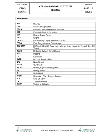
OPERATIONPRE-INSTALLATION INSTRUCTIONSPRE-OPERATION PROCEDURESCARRIER SIZENITROGEN CHARGECheck the Specifications section of this manual to determine correct carrier size, hydraulic flow and pressurerequirements.The breaker has been properly charged with nitrogen atthe factory and is ready to use.If hydraulic pressure, hydraulic back-pressure, hydraulicflow or excavator weight class are exceeded, the toolwarranty is void.EXISTING EQUIPMENT HYDRAULICS VS.APPLICATION ATTACHING KITSUsing existing equipment hydraulic auxiliary systemsfor operating hydraulic tools could cause problems forthe hydraulic tool and the hydraulic system if not set upproperly. Simply plugging into the hydraulic system without confirming pressure and flow to the hydraulic tool isnot a good practice. Spare spool valves, dipper circuits,etc., are just a few examples of easily accessible hydraulic circuits which could prove to cause problems forhydraulic tool usage.TOOL BIT LUBRICATIONGrease the top 250 mm / 10 in. of the breaker tool bit before installing. During operation, the tool can be greasedthrough the grease fitting. Grease is required.Make sure the tool bit is against the piston by placing thetool bit against the ground and then putting down pressure on the breaker. See the illustrations below.GreaseThis Areaof BitStanley Hydraulic Tools has for many years developedATTACHING KITS for adapting to existing hydraulic systems of many popular carriers.If your equipment does not contain an attaching kit, askyour Stanley dealer for information, installation, andpricing on a kit which matches your equipment needs.250 mm/10 in.Tool BitTEST THE HYDRAULIC SYSTEM1. Have your Stanley dealer test the carrier hydraulicsystem to make sure the system is operating at themanufacturers specified capacity and pressure ratings.2. Be sure the fluid in the hydraulic system is clean.3. Check the hydraulic filter. Replace the filter if dirty ordeteriorated.4. Have your Stanley dealer test the circuit to whichthe breaker will be connected to make sure that thecircuit is supplying the specified flow and pressurerating for the breaker. See the Specifications sectionof this manual.Grease FittingMB05 User Manual 9
OPERATIONWARNINGGreasing the tool bit without down pressure on thebreaker results in grease filling the space betweenthe piston and the tool bit. When the breaker is nextactivated, the piston will strike the grease at a speedwhich will pressurize the grease resulting in seal andgrease zerk failure.Piston in Down PositionAgainst Tool BitTool StopAlways wear eye protection when installing orremoving the tool retaining pin.LOW TEMPERATURE WARM-UPPROCEDURE1. After starting the carrier, warm-up the hydraulic system at engine idle until hydraulic lines are warm tothe touch.2. With the carrier at idle and the breaker suspendedin the air or with minimal down pressure, turn on thebreaker to gradually warm up its internal components.Lower Bushing3. When the hydraulic system and breaker are warm,proceed with operation.Tool BitLONG TERM STORAGEGrease Will FillThis SpacePiston not againstTool Bit leaving spacebetween the Piston andBit.Tool StopLower BushingTool BitSECURING THE TOOL BIT1. The tool retainer is shipped installed in the breaker.2. Remove the stop pin and plug.3. Drive out the tool retainer.4. Grease the top area of the tool bit as shown in theillustration on page 9.5. Install the tool bit making sure the notch is alignedwith the lower body retainer pin holes.6. Install the tool retainers.10 MB05 User ManualWARNING1. Remove the tool bit, clean the tool stop and the lower bushing. Thoroughly coat the surfaces of the toolstop and the lower bushing with grease.2. If hoses are attached to the breaker, install plugson the hose ends. If hoses are removed from thebreaker, install plugs on the hose ends and installplugs in the breaker IN and OUT ports.3. Store the breaker in a vertical position. Do not storethe breaker horizontally for extended periods.
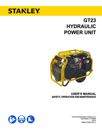
OPERATIONOPERATING THE BREAKERPREPARATION FOR USERead the section in this manual titled Pre-Operation Procedures before operating a breaker. Failure to follow thepreparation instructions can result in severe damage tothe breaker and carrier and void the warranties of both.EXCAVATORSWith the breaker tool in place on the material to beworked, position the excavator so the dipper is at approximately 45 and the breaker is almost vertical. Thetracks of the excavator should be in line with the boomand the breaker.POSITIONING THE CARRIERBACKHOESWith the breaker tool in place on the material to beworked, position the backhoe so the boom is halfway up(45 ) and the dipper holds the breaker almost vertical.Lower the loader bucket until the weight is off the fronttires.Apply down force.POSITIONING THE BREAKER TOOL ONTHE WORK MATERIALPosition the tool bit near the edge of the work material,not in the center or far from the edge. Position the tool 6– 18 inches (depending on the material) from the edge.Breaking off smaller pieces of rock or concrete usuallyaccomplishes more than trying to break larger pieces.Apply down pressure.Apply down force to the boom/dipper until the rear of thebackhoe is raised off the ground. Rear tires and stabilizers should be off the ground so the total rear weight ofthe backhoe is on the breaker tool. The breaker is moreefficient when adequate down force is applied.Break near the edge.On flat material or rock, the breaker should be verticalor “curled” back slightly to direct the impact force downward and toward the backhoe. This directs the forceback toward the edge of the work material. If the toolis positioned in the center of the work, or too far fromthe edge, the energy will be absorbed into the materialwithout cracking it. Do not run the breaker longer thanMB05 User Manual 11
OPERATION15 – 20 seconds. If breakout does not occur within thistime, move the breaker to another position.On flat material such as concrete runways, starting tobreak in the middle of the material may cause vibrationsto be transmitted throughout the breaker and excavatorbecause the material has no place to break to. Alwaystry to start at a point which will permit the material tobreak out.MAINTAIN DOWN PRESSUREMaintaining hard contact with the surface of the materialto be broken in addition to maintaining adequate “downforce” is very important. Always keep “down pressure”or “down force” on the point of the breaker by lifting thewheels, tracks, or stabilizers slightly above the ground.This method takes the “slack” out of the bracket andboom pivots, and reduces the impact on the pivots inthe boom.The operator needs to be constantly aware of the amountof down pressure being applied and be able to adjust itif necessary. Not enough down pressure results in lowproduction and accelerates wear and tear on the equipment. Too much down pressure may cause the breakerhousing to violently crash into the broken material when“break-through” occurs.In any breaking job, the operator should make every effort to “follow” the breaker with “down pressure” as themachine breaks farther into the material. The breakershould be stopped as soon as “break-through” occurs orif it is apparent that good solid blows are not occurring.BREAKINGThe operator should note the sound of the blow whenthe breaker is running. With experience, the operator willbe able to tell the difference between a good solid blowand a hollow sounding blow. A hollow blow means thatsolid blows are not occurring and breaker should be repositioned.Do not break continuouslyin one place.CAUTIONContinuous penetration in the same area for lengthyperiods will create excessive temperatures at the tipof the tool bit resulting in loss of temper (hardness)of the bit, mushrooming of the tip of the bit and maylead to failure of the bit.Use a “scoring” method of breaking when crackingthe material becomes difficult. This technique involvesstriking the rock or concrete at several places along aline where you want the crack to occur. Most materialsbreak sooner when struck several places along a linethan when struck repeatedly in one location. On eachline, the breaker tool should be continually repositioned.Practice determines the best length of time to stay inone spot. (15 – 20 seconds) and how far to move thebreaker tool.Continuous tool penetration usually does not do muchgood. If the material does not break with 3 – 6 inches oftool penetration, it usually won’t break with full penetration. The time used for additional penetration could bebetter used to strike blows in another place.Many materials do not respond well to continued hammering in one place. The breaker tool should be repositioned on the work each time the tool penetrates butdoes not crack the material.12 MB05 User ManualScoring with the breaker
OPERATIONBreaker tool binding can cause erratic breaker operation and premature wear on the tool shank. Breaker toolbinding is caused by failure to direct the down force inthe direction of the tool bit.Breaker tool bit bindingCAUTIONDo not pry with bit and breaker. The tool bit maybreak causing injury.Excessive side force cocks the tool in its bore, preventsproper movement and causes premature tool shankand bushing wear. Since the breaker tool bit must bepushed up into the breaker to operate, a binding toolprevents the breaker from operating correctly. Bindingalso causes the tool bit and tool bushings to seize andoften results in breakage of one or more breaker components.Always direct the down pressure force in a line towardthe point of tool contact with the work.Moving rocks with the tool bit is another method of binding the tool bit. This practice should be avoided as it maycause tool bit failure.Rebar reinforced concrete introduces the problem ofconcrete chunks being held together by the rebar afterthe concrete has been broken. The best approach to thisproblem is to use a chisel point tool which permits cutting the rebar with the breaker. Another method is to periodically cut the rebar with an oxy-acetylene torchBLANK FIRINGTo understand “Blank Firing”, the operator needs to beaware that the tool bit is able to drop down in the lowerbody cavity, far enough so that the piston cannot strike it,when the tool bit is not in contact with the work surface.“Blank Firing” occurs whenever the breaker is operatingand the piston is not able to strike the tool bit solidly ornot strike the tool bit at all. “Blank Firing” accelerateswear and tear on breaker and carrier components andmay result in failure of one or more components. Excessive “Blank Firing” may be considered equipment abuseand may result in voiding warranties.Break-through or difficult surface contact results in“Blank Firing” when the material being broken fracturesand the tool bit is no longer in “hard contact” with thematerial but is still pushed high enough in the lower bodycavity so that the piston can strike it. In this position, thepiston strikes the tool bit and the tool bit, in turn, is drivenagainst the retaining pins because it is not in sufficientcontact with the material to be broken. The energy is absorbed by the retaining pins, other breaker components,and the carrier boom components. “Blank Firing” of thistype can be experienced in trench work where obtaining striking contact with the work surface is difficult orthe wrong tool bit is used, or in flat rock work where theoperator fails to stop operation of the breaker when slippage, fracturing or material break-through occurs.“Blank Firing” as a result of operator error occurs whenthe tool bit is not in contact with the work surface to bebroken and is allowed to drop down in the lower bodycavity so that the piston is not able to strike it. Instead,the downward movement of the piston will be stoppedby an internal oil cushion located at the bottom of thepiston’s stroke and the energy of the piston will be absorbed by breaker components and excavator boomcomponents. “Blank Firing” of this type can be experienced when the operator fails to stop operation of thebreaker when the material fractures or material breakthrough occurs, or during re-positioning of the breaker.While “Blank Firing” cannot always be avoided, it can bekept to a minimum by avoiding the above conditions asmuch as possible.MB05 User Manual 13
OPERATIONUNDERWATER USAGEGREASE THE BITUnderwater usage of the breaker will cause damageto internal components. Even if the breaker is partiallysubmerged, water is introduced to an area between thetool bit and piston. On the piston down cycle, the waterbecomes compressed and damages adjacent components.Grease should be applied to the upper end of the breaker tool bit each time it is installed. Thereafter, the toolshould be greased at the fitting to reduce wear in thelower body and bushings of the tool. See Greasing TheTool Bit in the sections titled Pre-Operation Procedures.NOT USEUNDERWATERDo notDOuse underwaterwithoutsupplying air to breaker.CAUTIONNo part of the breaker may be submerged in water.Underwater usage of the breaker will causeinternal damage to the breaker. Consult Stanley formodifications and specific warranty coverage if youhave an underwater requirement.14 MB05 User Manual
TROUBLESHOOTINGThis section describes how to find and resolve problems users may experience. If a situation occurs that is notcovered, call your Stanley Customer Service representative for assistance.WARNINGInspecting the tool or installing parts with the hydraulic hoses connected can result in severe personal injuryor equipment damage. To prevent accidental startup, disconnect the hydraulic power before beginning anyinspection or installation task.If symptoms of poor performance develop, the following chart can be used as a guide to correct the problem.When diagnosing faults in operation of the tool, always check that the hydraulic power source is supplying thecorrect hydraulic flow and pressure to the tool as listed in the table below. Use a flowmeter known to be accurate.Check the flow with the hydraulic oil temperature at least 80 F/27 C.PROBLEMBreaker will not fire.CAUSELow hydraulic oil level.Fill reservoir.No flow to breaker.Have hydraulic circuit tested byauthorized dealer/distributor perapproved procedure.Main relief set low.Breaker runs slowly.Internal damage.Have unit serviced by an authorizeddealer/distributor.Damaged quick couplers.Replace.Low hydraulic flowHave hydraulic circuit tested by anauthorized dealer/distributor perapproved procedure.Excessive heat build up.Excessive nitrogen pressure.Internal leakage.Breaker runs erratically.SOLUTIONLow or excessive back-pressure.Damaged switch or connection.Have unit serviced by an authorizeddealer/distributor.Have carrier serviced by anauthorized dealer/distributor.Relief set too low.Internal damage.Breaker runs but at reduced power.Tool binding.Add grease to tool shank. Do notpry while operating.Low accumulator charge.Have unit serviced by an authorizeddealer/distributor.Excessive back-pressure.Relief set too low.Breaker leaks oil around tool bit andtool bushing.Lower seals failed.Have unit serviced by an authorizeddealer/distributor.Hydraulic system overheats.Main relief set low.Have unit serviced by an authorizeddealer/dis
SERVICING THE STANLEY HYDRAULIC BREAKER. This manual contains safety, operation, and routine mainte - nance instructions. Stanley Hydraulic Tools recommends that servicing of hydraulic tools, other than routine main-tenance, must be performed by an authorized and certified dealer. Please read the following warning. WARNING