Transcription
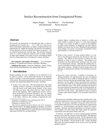
Published in ACM TOG (SIGGRAPH conference proceedings) 22(3):554–561, July 2003Reanimating the Dead: Reconstruction of Expressive Faces from Skull DataKolja Kähler Jörg Haber†Hans-Peter Seidel‡MPI Informatik, Saarbrücken, GermanyAbstractFacial reconstruction for postmortem identification of humans fromtheir skeletal remains is a challenging and fascinating part of forensic art. The former look of a face can be approximated by predicting and modeling the layers of tissue on the skull. This workis as of today carried out solely by physical sculpting with clay,where experienced artists invest up to hundreds of hours to crafta reconstructed face model. Remarkably, one of the most populartissue reconstruction methods bears many resemblances with surface fitting techniques used in computer graphics, thus suggestingthe possibility of a transfer of the manual approach to the computer.In this paper, we present a facial reconstruction approach that fitsan anatomy-based virtual head model, incorporating skin and muscles, to a scanned skull using statistical data on skull / tissue relationships. The approach has many advantages over the traditionalprocess: a reconstruction can be completed in about an hour fromacquired skull data; also, variations such as a slender or a moreobese build of the modeled individual are easily created. Last notleast, by matching not only skin geometry but also virtual musclelayers, an animatable head model is generated that can be used toform facial expressions beyond the neutral face typically used inphysical reconstructions.a)d)of a murder victim can be confirmed by superimposing a facial photograph with a properly aligned and sized image of the skull. If nophotograph is available, the look of the face can be reconstructed toa certain degree by modeling the missing tissue layers directly ontothe skull or a plaster cast made from it.The first documented case using three-dimensional facial reconstruction from the skull dates back to 1935 [Taylor 2001]. A keyexperiment was later performed by K ROGMAN [1946]: given thebody of a deceased person, he took a picture of the cadaver headbefore extracting the skull. The skull was provided to a sculptoralong with information about sex, origin, and age of the late owner,plus data on the average tissue thicknesses at several positions inthe face. From this material, a reconstruction sculpture was createdthat could be compared to the original head. Since that time, threedimensional facial reconstruction from the skull has been muchrefined, but the method has essentially remained the same. Researchers have examined the skull / skin relationships for differentethnic groups [Lebedinskaya et al. 1993] and analyzed the correspondences of skull morphology and facial features [Fedosyutkinand Nainys 1993]. Others found correlations between muscle activity and skull shape [Moore and Lavelle 1974; Weijs and Hillen1986]. In her comprehensive textbook, TAYLOR [2001] describesthe craft in great detail.Much of the fascination of the topic is due to the combined efforts of science and art, resulting in often astonishingly lifelike reconstructions, given the little available input (see Fig. 2). Manyparameters of the outward appearance of an individual cannot bereadily derived from the skull, though. The process is thus highlydependent on rules of thumb, the experience of the artist, and someguesswork. It is, for instance, next to impossible to reconstruct theshape of the ears based on scientific reasoning, although empirically there seems to be a relation of ear height to the length of thenose.Keywords: facial modeling, forensic art, face reconstructionIntroduction1.1c)Figure 1: Reconstruction of a face from the skull: a) scanning theskull; b) skull mesh tagged with landmarks; c) skin mesh with muscles fitted to the skull; d) textured skin mesh, smiling expression.CR Categories: I.3.5 [Computer Graphics]: Computational Geometry and Object Modeling—Physically based modeling I.3.7[Computer Graphics]: Three-Dimensional Graphics and Realism—Animation G.3 [Probability and Statistics]—Multivariate statisticsG.1.2 [Numerical Analysis]: Approximation—Approximation ofsurfaces and contours1b)BackgroundFor well over a hundred years, forensic art and science has beenassisting law enforcement. One of the major areas of concern inthis area is facial reconstruction for postmortem identification ofhumans from their physical remains. Manual reconstruction andidentification techniques build on the tight shape relationships between the human skull and skin: for instance, the presumed identity e-mail:kkaehler@acm.orghaberj@acm.org‡ e-mail: hpseidel@mpi-sb.mpg.de† e-mail:1.2The Manual Reconstruction ProcessThe traditional work process for facial reconstruction begins withpreparation of the skull. Since the skull is often evidence in a criminal case, great care needs to be taken in handling it: some partsare extremely thin and fragile, especially in the nose and the orbits.For identification, the teeth often provide a lot of useful informa-1
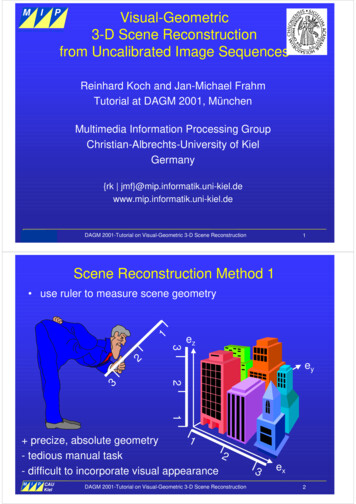
Published in ACM TOG (SIGGRAPH conference proceedings) 22(3):554–561, July 2003animation on the reconstructed head in a physics-based facial animation framework.The remainder of this paper is organized as follows: after reviewing related work in Section 2, we discuss acquisition of skulldata and interactive landmark placement for setting up surface constraints in Section 3. Section 4 describes the structure of our generichead model and how it is fitted to the skull. Animation and texturegeneration for the resulting head model are touched upon in Section 5. We present examples in Section 6 and draw conclusionsfrom our results in Section 7.Figure 2: Comparison of sculpted reconstructions with photographs. Left: male subject; right: female subject. (Images: Copyright c [Helmer et al. 1993], reprinted by permission of Wiley-Liss,Inc., a subsidiary of John Wiley & Sons, Inc.)22.1Computer-Aided Face ReconstructionPerhaps due to the lack of rigid taxonomies and hard rules, the useof computers and computer graphics in this forensic application isstill very limited. The procedures described above cannot be casteasily into a computer program that produces good results in an automated manner—the experience and judgment of the practitionerremain a vital part of the system.In law enforcement practice, computer-aided techniques restrict to relatively simple image and video manipulation: facephotographs are used for skull superimposition [Grüner 1993;Miyasaka et al. 1995], while image warping and retouching enablea basic simulation of aging [Taylor 2001, p. 253]. This situationis unfortunate, since the traditional three-dimensional face reconstruction process is extremely time-consuming and expensive. Itis hardly feasible to produce a variety of different plausible reconstructions from one skull, simply due to the effort that has to be putinto the creation of each model. Also, repeated physical handlingof the original skull increases the risk of damage.One prototypical computer-based face reconstruction system, allowing fitting of a generic hierarchical B-spline head model to askull mesh, is described by A RCHER in her Master’s thesis [1997].The user places dowels on a skull model with prescribed tissuethickness values, resulting in targets for a B-spline surface fittingprocess. The interpolation process is tricky and requires carefulpreparation of the template head model.In the approach presented by M ICHAEL and C HEN [1996], asource head model Hs that includes a skull Ss is deformed using avolume distortion function V such that the deformed source skullapproximately matches the target skull St : V (Ss ) St . It is assumed that the deformed source head model V (Hs ) bears a goodresemblance to the (unknown) target head model. The volume distortion function V is set up as a field warp using fourty pairs of discfields, which are manually placed around the skull. No details aregiven about the placement of these control fields.tion, so a dental analysis is usually performed at this stage. For thereconstruction of the lower face, the mandible needs to be properlyaligned and secured to the skull. In cooperation with an anthropologist, and possibly given more information from the remains of thevictim, an estimation of age, ancestry, sex, and stature can now beobtained.The actual face reconstruction proceeds with one of two available approaches: the anatomical method and the tissue depthmethod. The anatomical method attempts reconstruction by sculpting muscles, glands, and cartilage, fleshing out the skull layer bylayer. This technique is more often used in the reconstruction offossil faces, where no statistical population data exists [Zollikoferet al. 1998]. As TAYLOR states, this technique is very time consuming, occupying “many hundreds of hours”. It also requires a greatdeal of detailed anatomical knowledge. Therefore, the alternativetissue depth method has become the more popular reconstructiontechnique in law enforcement. Here, standard sets of statistical tissue thickness measurements at specific points on the face are used.Each measurement describes the total distance from skin surface tothe skull, including fat and muscle layers. The method is thus morerapid than the anatomical method and does not require as muchanatomical knowledge. Such measurements have been collected formales and females of several racial groups, using needles, X-rays,or ultrasound techniques. The tissue depth data most often used bypolice artists today was collected primarily by R HINE et al. [Rhineand Campbell 1980; Rhine and Moore 1984]. The data is sortedinto “slender”, “normal”, and “obese” groups, as well as by sex andrace.Given the set of measurements, tissue depth markers are nowplaced on the skull or a cast made from it, reflecting the tissuethickness at the sample points. These markers are oriented orthogonally to the skull surface, corresponding to the direction of the tissue thickness measurements. Using the markers and other featureson the skull for guidance, the face is modeled on top of the skullusing clay. A snapshot of the beginning stages of a reconstructionusing the tissue depth method is shown in Fig. 3.1.3Previous and Related WorkOur approachLooking at the facial reconstruction process as described abovefrom a computer graphics perspective, it essentially boils down toa surface interpolation problem. We thus implement the manual“dowel placement” method as an interactive procedure, obtainingposition and distance constraints that define the relation betweenskin and skull at selected sample positions. The sculpting of theskin surface is mapped to a volume deformation applied to a headmodel template, satisfying these constraints. The deformation approach has the additional advantage of being applicable to additional structures attached to the template: in our system, we mapa muscle structure to the fitted head model (see Fig. 1), enablingFigure 3: Modeling the face with clay on top of the skull using thetissue depth method. (Images [Taylor 2001], reprinted by permission.)2
Published in ACM TOG (SIGGRAPH conference proceedings) 22(3):554–561, July 2003tissue, and skin. S CHEEPERS et al. [1997] as well as W ILHELMSand VAN G ELDER [1997] introduce anatomy-based muscle modelsfor animating humans and animals, focusing on the skeletal musculature. Skin tissue is represented only by an implicit surface withzero thickness [Wilhelms and Van Gelder 1997].We build our system on the deformable, anatomy-based headmodel described by K ÄHLER et al. [2002]. There, a generic facemesh with underlying muscle and bone layers is deformed to matchscanned skin geometry. This process is adopted here to match themuscle and skin layers to given skull data instead.A deformation technique similar to the one used in our approachis employed by VANEZIS et al. [2000]. A facial template chosenfrom a database of scanned faces is deformed to match the position of target face landmarks, which have been derived from addingstatistical tissue thickness values to the corresponding skull landmarks. The resulting reconstructed heads are not always complete(for instance, the top of the head is usually missing). The authorssuggest to export an image of the reconstructed head and to apply afinal image-processing step to add eyes, facial and head hair.The above methods require a lot of manual assistance in setting up the interpolation function [Archer 1997; Michael and Chen1996], or rely on a database of head templates [Vanezis et al. 2000].In contrast, we develop reconstructions from one head templatewith relatively few markers, and use additional mechanisms to improve reconstruction results (see Section 4.3). Our approach alwaysgenerates complete head models. Instead of using higher-order surfaces or point samples, the surface of our deformable head template is an arbitrary triangle mesh, simplifying later artistic modifications of the result using standard modeling tools. To the best ofour knowledge, integration of expressive facial animation is not discussed by any other computer-aided facial reconstruction approach.Other than explicit treatment of facial reconstruction, the creation of virtual head models based on human anatomy is well researched and documented in the computer graphics literature. Major developments in this area are discussed in the following section.2.23Preparation of the SkullOur approach uses three-dimensional skull data acquired, for instance, from volume scans and extraction of the bone layers, or byrange scanning a physical skull. The test data used for the examples in Section 6 was acquired using both types of scans. To speedup processing, a triangle mesh of the skull model comprised of 50250k polygons is produced by mesh decimation techniques [Garland and Heckbert 1997]. In general, the original data should besimplified as little as possible since minute details on the skull cangive important clues for the reconstruction. The mesh resolution ischosen for adequate responsiveness of our interactive skull editorapplication. In practice, it is helpful to have the original data set (orthe physical skull) ready as a reference during editing.In the editor, the skull model is equipped with landmarks, asshown in Fig. 4. Points on the skull surface are simply picked tocreate a landmark, which can then be moved around on the surface for fine positioning. Each landmark is associated with a vectorin surface normal direction, corresponding to the typical directionof thickness measurements. As can be seen on the right image inFig. 4, some skull / skin correspondences are in fact non-orthogonalto the skull surface in the area of the lips. This is corrected forat a later step of the fitting process, as described in Section 4.3.The landmark vector is scaled to the local tissue thickness, whichis looked up automatically by the landmark’s assigned name in atable based on R HINE’s data (see Section 1.2). The specific set oflandmarks used in our system is listed in Appendix A.Human Head ModelingA variety of techniques exists to create a face model from images orscan data. In the method presented by L EE et al. [1995], animatablehead models are constructed semi-automatically from range scans.A generic face mesh with embedded muscle vectors is adapted torange scans of human heads. This process relies on the planar parameterization of the range scans as delivered, for instance, by theCyberware digitizers. P IGHIN et al. [1998] interactively mark corresponding facial features in several photographs of an individualto deform a generic head model using radial basis functions. Animation is possible by capturing facial expressions in the processand blending between them. C ARR et al. [2001] use radial basis functions to generate consistent meshes from incomplete scandata. Employing a large database of several hundred scanned faces,B LANZ et al. [1999] are able to create a geometric head model fromonly a single photograph. This model has the same resolution asthe range scans in the database and cannot be readily animated. Inthe context of medical imaging, S ZELISKI et al. [1996] minimizethe distance between two surfaces obtained from volume scans ofhuman heads by applying local free-form deformations [Sederbergand Parry 1986] and global polynomial deformations. The methoddoes not require specification of corresponding features on the geometries.Several facial animation systems use an approximation of thelayered anatomical structure. WATERS [1987] represents skin andmuscles as separate entities, where muscle vectors and radial functions derived from linear and sphincter muscles specify deformations on a skin mesh. In contrast to this purely geometric technique,physics-based approaches attempt to model the influence of musclecontraction onto the skin surface by approximating the biomechanical properties of skin. Typically, mass-spring or finite element networks are used for numerical simulation [Platt and Badler 1981;Lee et al. 1995; Koch et al. 1998]. From an initial triangle mesh,T ERZOPOULOS and WATERS [1990] automatically construct a layered model of the human face. The model structure consists of threelayers representing the muscle layer, dermis, and epidermis. Theskull is approximated as an offset surface from the skin. Free-formdeformations are employed by C HADWICK et al. [1989] to shapethe skin in a multi-layer model, which contains bones, muscles, fat44.1Fitting the Deformable Head ModelHead Model StructureWhen the skull is tagged with landmarks, it serves as the target fordeformation of the generic head model shown in Fig. 5. Since thehead model is used in a physics-based animation system, it doesFigure 4: Skull landmark specification in the mouth area. Left:snapshot from our landmark editor; right: correspondences betweenskull and skin markers (Image after [y’Edynak and İşcan 1993])3
Published in ACM TOG (SIGGRAPH conference proceedings) 22(3):554–561, July 2003a)b)where p R3 is a point in the volume, ci R3 are (unknown)weights, R R3 3 adds rotation, skew, and scaling, and t R3is a translation component. The φi are defined by the source skinlandmark points. According to B OOKSTEIN [1997], for deformation of biological solids an approach based on thin-plate splinesis favorable. We thus use the simple biharmonic basic functionφi (p) : p pi 2 , which minimizes bending energy for the deformation [Duchon 1977].To remove affine contributions from the weighted sum of thebasic functions [Pighin et al. 1998; Carr et al. 2001], we include theadditional constraintsc)nFigure 5: The deformable head model: a) head geometry with landmarks (blue dots), front view; b) side view; c) underlying muscles(red) created from layout grids (yellow). ci 0i 1 cTi pi 0.i 1The resulting system of linear equations is solved for the unknownsR, t, and ci using a standard LU decomposition with pivoting, toobtain the final warp function f. This function can now be usedaccording to Eq. (1) to transform a point p in the volume spannedby the landmarks. We apply f to the skin and muscle componentsof the generic model in the following ways:not only consist of the visible outer geometry. The encapsulatedstructure includes:the skin surface represented as a triangle mesh. The mesh resolution should be high enough to ensure good fitting results. Ourtemplate head mesh consists of 8164 triangles. The skin mesh is deformed by direct application of the function to the vertices of the mesh.virtual muscles to control the animation. Each muscle is specified by a grid laid out on the skin, the actual muscle shapebeing computed automatically to fit underneath the skin surface. Each muscle consists of an array of fibers, which cancontract in a linear or circular fashion. Our model includes24 facial muscles responsible for facial expressions. Fig. 5(c)shows the muscle layout on the head template. The muscles are transferred to the new geometry by warpingtheir layout grid vertices, followed by recomputation of theshape to fit the deformed skin mesh.Since our landmark set is comprised of only 40 landmarks (seeAppendix A), the computed deformation doesn’t properly align theskin to the skull in all places, as can be seen in Fig. 6(a). Interactive specification of more landmarks puts an undesirable additionalburden onto the user, so additional landmark pairs are computed automatically by interpolation between existing ones on the upper andback part of the cranium, as well as on the mandible, as shown inFig. 6(b). The thickness value of an interpolated skull landmark isalso interpolated, where only such skull areas are chosen for landmark interpolation where the tissue thickness is near-constant. Tissue depth interpolation would be problematic, for instance, in themid-face area, where thickness values change drastically from thecheekbone to the mid-face region below.a mass-spring system connecting skin, muscles, and skull, builtafter the head model is fitted to the skull. For animation, muscles pull at spring nodes attached to their surface, in turn causing deformation of the spring mesh in the skin surface layer.landmarks defined on the skin surface, as shown in Fig. 5(a) and(b). The majority of these landmarks corresponds to the landmarks interactively specified on the skull. These landmarkpairs control the basic fitting of the head structure as describedin Section 4.2. A few additional landmarks are only definedon the skin and are used for the final adjustments of the reconstructed shapes discussed in Section 4.3.4.3The head model is similar to the one in [Kähler et al. 2002], wheredetailed descriptions of the muscle model and animation approachcan also be found.4.2nandAdditional Reconstruction HintsThe tissue depth values at the marker positions define the basicshape of the reconstructed head, assuming depth measurements being always strictly orthogonal to the skull surface. As mentioned inSection 3, this assumption is not always valid. A number of rulesare thus used in traditional facial reconstruction to help locate certain features of the face based on the skull shape, employing empirical knowledge about shape relations between skin and skull [TaylorLandmark-Based RBF DeformationGiven the deformable head model with n predefined skin landmarkpositions pi R3 and the corresponding landmarks si R3 (i 1, . . . , n) specified on the skull, we set up a space deformation thatfits the skin and the muscle layout to the skull.The target skull landmarks have associated tissue depth vectorsdi , so corresponding skin landmark positions qi are defined asqi s i d i .The problem can now be treated as one of interpolation: we need tofind a function f that maps the pi to the qi :qi f(pi ),i 1, . . . , n.The unknown function f can be expressed by a radial basis function,i.e., a weighted linear combination of n basic functions φi and anadditional explicit affine transformation:(a) ci φi (p) Rp t,(c)Figure 6: Fitting stages, shown on the lower face. a) Warp using only user-specified landmarks (some skull areas still intersecting the skin); b) with automatically interpolated landmarks on themandible; c) using additional heuristics for lip and nose shaping.nf(p) (b)(1)i 14
Published in ACM TOG (SIGGRAPH conference proceedings) 22(3):554–561, July 2003 The width of the mouth is determined by measuring the frontsix teeth, placing the mouth angles horizontally at the junctionbetween the canine and the first premolar in a frontal view.Two vertical guides are used for positioning the ch landmarkslocated at the mouth angles (vertical lines in Fig. 7, bottomrow). The thickness of the lips is determined by examining the upper and lower frontal teeth. Seen from the front, the transition between the lip and facial skin is placed at the transitionbetween the enamel and the root part of the teeth. Two horizontal guides are placed by the user at the upper and lowertransition, respectively. This determines the vertical positionof the id and sd landmarks marking the lip boundary (top andbottom horizontal lines in Fig. 7, bottom row). The parting line between the lips is slightly above the bladesof the incisors. This determines the vertical placement of thech landmarks (middle horizontal line in Fig. 7, bottom row).Using these heuristics, a better estimate of the mouth and noseshapes can be computed. The effect is strongest on the lip margins,since the assumption of an orthogonal connection between corresponding skin and skull landmarks is in fact not correct at thesesites, as the right part of Fig. 4 shows. The initial deformation thusgives a good estimate of the tissue thickness of the lips while thesecond deformation using the information provided by interactiveguide adjustment refines the vertical placement of the lip margins.Figure 7: Comparison of heuristics used in traditional reconstruction (left) with our graphical interface (right). (Note: differentskulls are used in the adjoining images.) Top: estimation of nosewidth; center: positioning of the nose tip; bottom: setting lip width,height, and mouth corner position.5In manual facial reconstruction, a neutral pose of the face is preferred as the most “generic” facial expression. Other expressionscould be helpful for identification purposes, but the cost of modeling separate versions of the head model is prohibitive. In our virtual reconstruction approach, this does not pose a problem. Sincethe fitted head model has the animatable structure of skin and muscles, different facial expressions can be assumed by setting muscle contractions, as in other physics-based facial animation systems [Kähler et al. 2001; Lee et al. 1995]. Fig. 8 shows how musclesare used to form different facial expressions.For a completely animatable head model, it is necessary to include a separately controllable mandible, a tongue, rotatable eyeballs, and eye lids into the head model. We have decidedly leftthem out of the reconstruction approach since these features arenot particularly useful in this application: while a modest changeof expression such as a smile or a frown might aid identification,rolling of eyes, blinking, and talking would probably not. It is alsonearly impossible to correctly guess details such as a specific wayof speaking—errors in this respect would produce rather misleading results in a real identification case. The effort of placing tongue,eye, and potentially teeth models thus does not offset the benefits.2001]. We have translated some of these heuristics for use with theskull landmark editor: the final fitting result, as shown in Fig. 6(c),is obtained by including this additional user input.To keep the user interface uniform, most rules are expressed bythe placement of vertical and horizontal guides in a frontal view ofthe skull. From this user input, the placement of a few landmarkson the skin is adjusted, resulting in a new target landmark configuration. The updated landmark set is used to compute another warpfunction, which deforms the pre-fitted head model in the adjustedregions. Five rules influence the shape of the nose and the shape ofthe mouth, as shown in Fig. 7: The width of the nose wings corresponds to the width of thenasal aperture at its widest point, plus 5mm on either side inCaucasoids. In the editor, the user places two vertical guidesto the left and right of the nasal aperture. From their position,the displacement of the two al1 skin landmarks placed at thenose wings is computed (cf. Fig. 7, top row). The position of the nose tip depends on the shape of the anterior nasal spine. According to K ROGMAN’s formula [Taylor2001, p. 443], the tip of the nose is in the extension of the nasalspine. Starting from the z value of the tissue depth marker directly below the nose (mid-philtrum, see Appendix A), theline is extended by three times the length of the nasal spine(cf. the white and yellow lines in the rightmost image ofFig. 7, middle row). In the editor, begin and end points ofthe nasal spine are marked. The prn landmark at the nose tipis then displaced according to the formula.1 see,Facial Expressions and RenderingFigure 8: Expressions on the generic head model and the corresponding muscle configurations.e.g., [Farkas 1994] for a definition of standard facial landmarks5
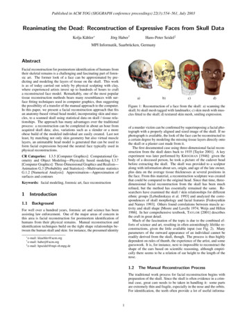
Published in ACM TOG (SIGGRAPH conference proceedings) 22(3):554–561, July 2003Figure 9: Examples of facial reconstructions created with our system. Top: model created from a scanned real skull, showing fit of skinto skull, transferred muscles, and two facial expressions. Middle: Reconstruction from a volume scan of a male, showing the actual faceas contained in the data, superimpositions of the actual and the reconstructed face with the skull, and the reconstruction with neutral and“worried” expression. Bottom: Reconstruction from volume scan of a female with strong skull deformations. The CT data sets don’t containthe top and bottom of the heads, thus the source skull and face models are cut off. The actual head height had to be guessed in these cases.probably was a war victim or a soldier. After scanning the skull, theresulting mesh was simplified to 100k triangles. Interactive placement of skull landmarks and facial feature guides was relativelyeasy in this case since the skull is complete and in good condition.Due to its war-time origin, we assumed the face to be rather skinny,so we selected the “slender” tissue thickness table. Fitting resultscan be seen in Fig. 9, top row. Since the actual appearance of the individual is unknown, the accuracy of the reconstruction can only beguessed. Nonetheless, our reconstruction seems plausible. Notably,the shape of the chin, which can be predicted from the corresponding region on the skull, has been reproduced well.If additional information about the modeled person is available,for instance, from remnants of hair found with the skull, the resulting mesh can be
body of a deceased person, he took a picture of the cadaver head before extracting the skull. The skull was provided to a sculptor along with information about sex, origin, and age of the late owner, plus data on the average tissue thicknesses at several positions in the face. From this material, a reconstruction sculpture was created