Transcription
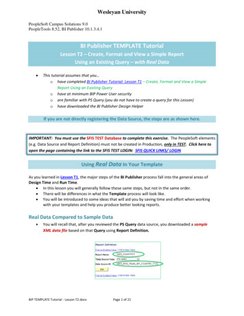
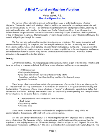
In this tutorial we are going to engrave some text onto an object, but thesame technique can be used to engrave a picture or any other solid objectinto another object. We're going to show how to use the Draft ShapeString,to create some text and then engrave in two different locations on a box.First open up FreeCAD and switch to the "Part Design" workbench so that wecreate a simple box. Create a new document and then create a new sketchwith the sketch orientation on the XY-Plane. Your result should look likethe following and have the same constraints:Now you can use the "Pad a selected sketch" to pad the box and make the Length10mm. If you click on the axometric view afterwards, your box should look like this:Now we need to create the text, and to make things easier, I always recommendcreating the text in a separate document to make it easier to work with. Socreate a new document, and then switch to the "Draft" workbench in that document:
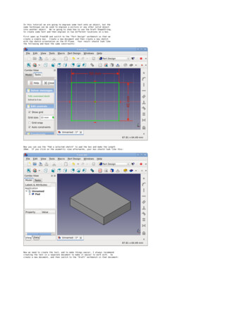
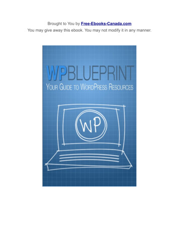
Now click on the big "S" to create a new ShapeString. Working in the ShapeStringcreation dialog box is a little annoying because it would have really been niceif they had included "Next" and "Prev" buttons so that you knew that you weregoing to goto different screens to set settings.but they didn't. As soon asyou click and create a ShapeString the first thing they want you to do is set theposition of your ShapeString, the box on the right that is requesting the values,put in ".00 mm" for all of them and then press [ENTER] on your keyboard to gotothe new set of options. When prompted for the "String" that is the text thatyou want to use, in this tutorial, just put in "Engrave Me" and press [ENTER].Next you'll be prompted for "Height", now be careful with this because it's theoverall height of the text. So for our example text "Engrave Me", put in aheight of "5 mm". That means if you measure from the top of the "E" to thebottom part of the "g" that will be 5mm, so just make sure you realize thatthe height isn't from the top of the "E" to the buttom of the "E", it's the topmost and bottom most part of the entire text. Press [ENTER] to goto the nextscreen. For "Tracking", I generally leave "0 mm", this is the inter-characterspacing, which if you want more spacing between characters then you can changethis, but for now just leave the default and press [ENTER]. You will now beprompted for what font you want to use. You can choose any TrueType fontthat you have, so click the "." to browse your system and I recommend goingto "/usr/share/fonts/truetype/" and if you have a "msttcorefonts" directoryin there, then go in there and select "times New Roman.ttf" and click "Open".If you don't have the exact font, that's fine, just choose any font. Youshould now have the text on your screen:Now let's make the text be a 3D object, so switch over to the "Part" workbenchand with the "ShapeString" object that you just created selected, click on the"Extrude a selected sketch" and make sure "X" and "Y" are set to "0.00" and the"Z" should be set to "1.00", and then set the Length to "8.00" (mm) and click"OK". Again, clicking on the axometric view should result in the following:
Now this means that we have a text object that is 8mm thick. I did thisbecause we actually only want to engrave our text 5mm deep into our box objectbut it's always better to make sure that your object is thick enough, whichyou'll see what I mean in the next few steps.So now it's time to bring our extruded text object into the document thatcontains our box. So click and highlight the "Extrude" object (which is thetext) and right-click and choose "Copy", when prompted about dependencies,click "Yes". Now switch back over to the first document that contains yourbox and paste the "Extrude" object into that document. I recomend switchingyour draw style to "Wireframe" so that you can see your 3D text inside ofyour 3D box, which should now look like this if you are still in the axometricview:Now select the "Extrude" object (the one you just pasted) that is in thedocument with your box and in the properties area select the "Data" taband then click the "." next to "Placement". In the Placement dialog boxset the translation for "X" to "-15 mm", leave "Y" at "0 mm" and set "Z" to"5 mm" and click "OK". You can swich your draw style back to "As is" andif you rotate your view it should now look similiar to the following where3mm of your text is sticking out the top of the box and 5mm of the text isinside of the box:
Now let's cut (engrave) the text from the box by doing a boolean operation.So first select the "Pad" (your box) and then press "Ctrl" and select the"Extrude" (your text). Again, make sure it's in that order.order isimportant. Now click the "Cut" (difference boolean operation) and yourtext should now be engraved:Now let's engrave the same text again onto a different face of the box, sofirst highlight and select the "Extrude" from the other document thatcontains just your text string and again "Copy" it and then past it backinto the document that has the box just like you did last time. And switchyour draw style to "Wireframe" again, and in axometric view you should see:
Now this time we need to rotate the text and bring it along the "Y" axisto get it to the face of our box, so first select the "Extrude001" objectwhich is the text and in the properties area select the "Data" tab and thenclick the "." next to "Placement". In the Placement dialog box set thetranslation for "X" to "-15 mm", set "Y" to "-15 mm" and set "Z" to"3 mm". Now under "Rotation", leave it set to "Rotation axis with angle"and for "Axis" set it to "X" and set the "Angle" to "90" and click "OK".You can swich your draw style back to "As is" and if you rotate your viewit should now look similiar to the following where 3mm of your text issticking out the front of the box and 5mm of the text is inside of the box:Now let's cut (engrave) the text from the box by doing a boolean operation.So first select the "Cut" (your box) and then press "Ctrl" and select the"Extrude001" (your text). Again, make sure it's in that order.order isimportant. Now click the "Cut" (difference boolean operation) and yourtext should now be engraved:
You've now engraved text onto two different faces of the box. You can usethis same technique if you were to scan in a picture, convert it to an SVG,import it, extrude it, and then engrave that picture onto a solid 3D object.Remember to save your new model to something like engraved box.fcstd.NOTE: I want to point out that technically speaking, you should place theShapeString text on the face of your object, and then in the "Part Design"workbench you can use the "Pocket" tool to engrave the text. By using the"Pocket" tool method, you don't have to convert your 2D object into a 3Dobject first.Look at Tutorial 3 for an example.
In this tutorial we are going to engrave some text onto an object, but the same technique c


![Database Management System [DBMS] Tutorial](/img/2/dbms-tutorial.jpg)