Transcription
U. S. Department of CommerceNational Oceanic and Atmospheric AdministrationNational Weather ServiceNational Centers for Environmental Prediction5200 Auth Road Room 207Camp Springs, MD 20746Technical NoteAn initial look at the CFSR Reanalysis winds for wave modeling†.Deanna M. Spindler ‡ , Arun Chawla, and Hendrik L. TolmanEnvironmental Modeling CenterMarine Modeling and Analysis BranchMarch 2011this is an unreviewed manuscript, primarily intended for informalexchange of information among ncep staff members†‡MMAB Contribution No. 290.e-mail: Deanna.Spindler@NOAA.gov
This page is intentionally left blank.
AbstractThe NCEP Climate Forecast System Reanalysis Reforecast (CFSRR)provides a 30-year homogeneous data set of hourly 1/2 degree spatialresolution winds. The increase in resolution compared to previous reanalyses,especially the temporal resolution, is expected to improve the hindcastresults of models driven by these wind fields; and the 30 years of data allowsfor multi-decadal studies, as well as for detailed wave model validationstudies.The ultimate goal is to use this new data set to generate a waveclimatology, but first it is important to test the data. Winds are notoriouslydifficult to validate, and there is limited ground-truth data to match spatiallocation and time. For this reason, several approaches have been used inthis study: the first compares the hourly wind speed and direction fromthe CFSRR data with that archived from NDBC buoys over the period ofone year (2005). The second assessed monthly wind percentiles for bothhemispheres. The third, compares the wave heights at these buoys withthe wave heights output by the WAVEWATCH III r model during threemonths of this same year (February through April). The model is runtwice, comparing the results using the archived NWW3 operational windsversus using the CFSRR winds.Preliminary results show that there is close agreement between thearchived operational winds and the CFSRR winds, suggesting that thenew reanalysis has a quality similar to that of present operational forecastmodels. The assessment of the monthly wave quantiles suggests that thereare three periods in the 30 year record with slightly different extreme windbehavior in the southern hemisphere.i
Acknowledgments. The authors thank Suranjana Saha for making the CFSRRdataset available for this study. The present study was made possibly by fundingfrom various NOAA sources.This report is available as a pdf file fromhttp://polar.ncep.noaa.govii
ContentsAbstract . . . . . . . . . . . . . . . . . . . . . . . . . . . . . . . . . . .Acknowledgments . . . . . . . . . . . . . . . . . . . . . . . . . . . . . .Table of contents . . . . . . . . . . . . . . . . . . . . . . . . . . . . . .iiiiii1 Introduction12 Model Structure33 Input Wind Fields3.1 NWW3 Winds . . . . . . . . . . . . . . . . . . . . . . . . . . . . .3.2 CFSRR Winds . . . . . . . . . . . . . . . . . . . . . . . . . . . .5554 Data Sets and Mean Behavior4.1 Archived Buoy Data . . . . . . . . . . . . . . . . . . . . . . . . .4.2 Hemispherical Quantile Data . . . . . . . . . . . . . . . . . . . . .7775 Detailed Results5.1 Basic Statistics . . . . . . . . . . . . . . . . . . . . . . . . . . . .5.2 Quantile-Quantile Plots . . . . . . . . . . . . . . . . . . . . . . .5.3 Taylor Diagrams . . . . . . . . . . . . . . . . . . . . . . . . . . .111111156 Conclusions21References . . . . . . . . . . . . . . . . . . . . . . . . . . . . . . . . . .iii23
This page is intentionally left blank.
1IntroductionWind speed and direction from the NCEP Climate Forecast System ReanalysisReforecast (CFSRR, Saha et al., 2010) are compared with archived buoy datafor the year of 2005, focusing on the Alaskan region. There are buoys withwind data – the sample distribution is from 68 to 79 per month. Therefore thisstudy is considered as a “glimpse” of how the wind product performs instead ofan in-depth analysis. Also included is an analysis of the behavior of monthlyhemispherical wind quantiles, as discontinuous behavior of such data has beenlinked to systematic changes in wave model biases.An indirect test of the wind fields was performed using sample computationswith the nested-grid full-spectral wind-wave model WAVEWATCH III r . Thismodel was run with both the operational (’NWW3’) winds, and with the newCFSRR high resolution winds. The test runs cover February through April of2005 with significant wave height for each buoy location requested every hour,and compared to archived buoy data.The WAVEWATCH III model is described in the user manual and systemdocumentation (Tolman, 2009). The manual describes the governing equations,numerical approaches, installation, compilation, and running of the model. Thenested-grid driver is described in Tolman (2007, 2008), and the grid generationtools used are described in Chawla and Tolman (2007, 2008).1
This page is intentionally left blank.2
2Model StructureA set of three nested grids was produced for the global ocean and the Alaskanregion. The full resolution ETOPO2 bathymetry was used as the reference grid,with the Strait of Juan de Fuca, Puget Sound, Columbia River Estuary, and SanFrancisco Harbor excluded. The lowest resolution grid (global, 30 min resolution)covers the worlds oceans. Nested inside are the intermediate (AK int, 10 minresolution) and highest resolution (AK cos, 4 min resolution) grids, which coveronly the Alaskan region. Intermediate and high resolution grids are available formany areas of the globe, but for expediency only these three grids were used inthis case.The wind wave model uses ice and winds (including the air-sea temperaturedifference) as input. The reanalysis daily ice concentration fields have a 1/2degree spatial resolution, and are derived from passive microwave from the SMMRand SSMI using the NASA Team algorithm (cf. Grumbine, 1996). The ice fieldsare updated daily. The wind fields used in the wave model will be described inthe following section.The wave model was started from calm conditions, and run for the months ofFebruary through April 2005. Significant wave heights were generated every hourat the buoy locations. Since it takes approximately two weeks for the wave modelin the Pacific Ocean to spin up from calm conditions, results will concentrate onthe months of March and April.The model requires spectral information that determine the frequencies thatwill be considered: a frequency increment factor, first frequency (Hz), number offrequencies (wavenumbers), the number of directions, and the relative offset ofthe directional increment. In this case, the following were used (from the wavemodel input file):1.1 0.035 29 24 0.5Here the model is intended to study wind waves with a period of no more than29 seconds, so the first frequency is 0.035 Hz. Note that the present operationalmodels run with higher spectral resolutions, and that the 30 year hindcast studieswill be run with the spectral resolution of the present operational global wavemodels.3
This page is intentionally left blank.4
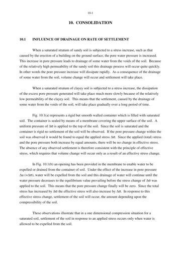
33.1Input Wind FieldsNWW3 WindsThe NWW3 winds are the operational winds that have been archived fromWAVEWATCH III r from 1997 to present. These winds are 1 degree resolution inlatitude and 1.25 degree resolution in longitude, and available every 3 hours. Theycover the globe from 78S—78N. Note that these winds represent an evolutionof atmospheric models, both in physics, assimilation, and resolution, and aretherefore not considered as a statistically homogeneous climatological dataset.Because of this, these winds should not be used to generate a climatology. Anexample wind field for the Pacific Ocean is shown in Fig. 3.1.3.2CFSRR WindsThe new NCEP Climate Forecast System Reanalysis Reforecast (CFSRR) entailsa coupled reanalysis of the atmospheric, oceanic, sea-ice and land data fromlate 1979 through 2010, and a reforecast run with this reanalysis (Saha et al.(2010). Here, only the reanalysis results will be used. This Reanalysis has muchhigher horizontal and vertical resolution of the atmosphere than the Global andthe North American Reanalyses. The high resolution winds used here are 10mhourly with 1/2 degree in spatial resolution, and cover the globe from 90S—90N. An example wind field for the Pacific Ocean is shown in Fig. 3.2. At firstinspection, the NWW3 and CFSRR winds appear compatible, with more sharpdetails in the wind field with the higher resolution (CFSRR) as expected.5
Fig. 3.1 : NWW3 winds valid 2000/01/18 06z.Fig. 3.2 : CFSRR winds valid 2000/01/18 06z.6
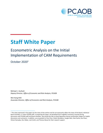
4Data Sets and Mean BehaviorThe comparison is between three different datasets of hourly wind speed anddirection, and significant wave height per buoy: the archived buoy data (labeled“Archive” in the figures), the results of running the wave model using NWW3operational winds (labeled “NWW3”), and the results using the CFSR reanalysiswinds (labeled “CFSW”).4.1Archived Buoy DataThe archived buoy data are Global Telecommunication System (GTS) buoyobservation data from buoys maintained by various operational agencies andprograms, and run through a basic quality control check. The wind data must beused carefully, since not all measurements may be at the same height. All buoydata in the archive represent equivalent neutral 10m wind speeds.As a first measure, the individual monthly means of wind speed and significantwave height for all buoys are compared in Fig. 4.1. There is generally a goodagreement between the three datasets. It is noticeable that the mean of thearchived wind speeds tend to be the greatest, and the mean of the NWW3operational wind speeds tend to be the lowest. As for the significant wave heights,those that result from using the CFSRR winds tend to have the highest values,whereas results from the NWW3 operational winds or the archived buoys arevery similar as would be expected. With higher resolution winds, any systemsare expected to represent stronger and sharper forcing.The difference in forcing by hourly (CFSW) versus 3-hourly (NWW3) windscan be appreciated by looking at the standard deviation from the archived values(Figure 4.2). The CFSRR winds show a greater monthly mean standard deviationthan the NWW3 operational winds, but with the exception of five buoys bothwind directions have similar standard deviations from the archived buoys. Thesharper forcing also yields significant wave heights that show greater deviationfrom the archived values.4.2Hemispherical Quantile DataAn additional quick test on the homogeneity of the wind fields for the entire 30year period was performed by computing various monthly quantile wind speedsfor the northern and southern hemisphere mid latitude wind speeds. Such ananalysis has previously linked changes in model biases in the souther hemisphereto discontinuous quantile wind speed behavior (Chawla et al, poster presentation,2010 WISE meeting, Brest, France). Results are presented in Figs. 4.3 and 4.4.For the northern hemisphere (Fig. 4.3), consistent behavior is observed for theentire 30 year period. Some variability is found in the highest percentile winds,7
Wind speed for 200504Buoy Monthly Mean109876501020304050Individual Buoys6070807080CFSWArchiveBuoy Monthly MeanSignificant wave height for 2005043210NWW31020304050Individual Buoys60Standard DeviationStandard DeviationStandard DeviationFig. 4.1 : Monthly mean for individual buoys for April 2005.Wind speed for 200504NWW3CFSW1.510.501020304050Individual Buoys6070806070807080Wind direction for 2005041.510.501020304050Individual BuoysSignificant wave height for 2005041.510.501020304050Individual Buoys60Fig. 4.2 : Monthly mean standard deviation for individual buoys for April 2005.8
99th95th90th80thMeanWind speed stats for the Northern ocean (25 N to 65 ig. 4.3 : Monthly wind speed for given probabilities for NorthernHemisphere mid latitudes99th95th90th80thMeanWind speed stats for the Southern ocean (65 S to 25 ig. 4.4 : Monthly wind speed for given probabilities for SouthernHemisphere mid latitudes9
but this variability appears to have a random nature as would be expected.For the southern hemisphere, however (Fig. 4.4), three distinct periods can beidentified with discontinuously changing behavior of the higher percentile winds.The separations between periods occur around 1995 and 2007. Because theunderlying models and analysis systems are kept constant throughout the entirereanalysis, the discontinuities are most likely due to the availability of individualdata sources. This behavior will be investigated in more detail at NCEP. For thepresent study it is sufficient to observe that the three regimes of behavior in thehigher percentile winds are likely to result in similar regimes in bias behavior inthe wave model in the southern hemisphere.10
55.1Detailed ResultsBasic StatisticsBuoys are also considered individually, and graphics from a few are presentedbelow. These were chosen since they have over 600 data records per monththroughout the spring of 2005, and are from different basins: NW Atlantic(Figures 5.1 and 5.2), Hawaii (Figures 5.3 and 5.4), and the NE Pacific (Figures 5.5and 5.6). These figures show the monthly statistics relative to the individualarchived buoy data for the results from the wave model driven by the CFSRRwinds.The correlation between the archived buoy and the model driven with CFSRRwinds is greater than 0.8 (Figures 5.1), with the exception of significant waveheights in August (Figures 5.2). This buoy is located off of South Carolina,and summer is the time for hurricanes. During summer of 2005 various stormsremained over the open Atlantic (hurricane Irene and tropical storm Lee forexample), and in September of 2005 tropical storm Ophelia passed by the easternshore of the US.Figures 5.3 and 5.4 show similar stats for a buoy off the coast of Kauai.Although the Hawaiian Islands saw a tropical depression at the beginning ofAugust and two hurricanes from the middle to end of September 2005, thestatistics do not reflect this. Both this buoy and the NW Atlantic buoy aredeep water buoys.5.2Quantile-Quantile PlotsAnother way to compare the wind speeds at a buoy is through a QuantileQuantile plot (also called Q-Q plot), which compares the shapes of two probabilitydistributions by plotting their quantiles against each other. If the distributionsare similar, then the points in the Q-Q plot will lie approximately on a line y x.If the distributions are linearly related, the points will also approximately lie ona line but not necessarily on the line y x.Here we present the Q-Q plots for the model results versus the archived datafor both February and April of 2005 at buoy 46002, which is a deep water buoyoff the coast of Oregon. These results are typical for all the buoys in the archive.For February 2005 (Figure 5.5), both the NWW3 and the CFSRR wind speedsare similar to the archived wind speeds, but the slope of the CFSRR quantiles iscloser to the y x line and therefore are in better agreement with the archivedbuoy data. Note that the points lie along a straight line, which suggests that thedata are normally distributed.In April 2005 (Figure 5.6), the slopes of both distributions are similar andvery close to the y x line, but the the points at the tail end (high wind speeds)have a flatter slope, especially in the NWW3 data plot. This implies that the11
Monthly Statistics for Wind Speed from Buoy 410028001.47001.2Stats Value0.85000.64000.4300Number of records60010.22000100 0.2Correlation Coeff12345Norm Stand Dev678Months of 20059RMS1011120Fig. 5.1 : Monthly statistics for wind speed from buoy 41002.Monthly Statistics for Wave Height from Buoy 410028001.47001.2Stats Value0.85000.64000.4300Number of records60010.22000100 0.2Correlation Coeff12345Norm Stand Dev678Months of 20059RMS1011120Fig. 5.2 : Monthly statistics for significant wave height from buoy 41002.12
Monthly Statistics for Wind Speed from Buoy 510018001.47001.2Stats Value0.85000.64000.4300Number of records60010.22000100 0.2Correlation Coeff12345Norm Stand Dev678Months of 20059RMS1011120Fig. 5.3 : Monthly statistics for wind speed from buoy 51001.Monthly Statistics for Wave Height from Buoy 510018001.47001.2Stats Value0.85000.64000.4300Number of records60010.22000100 0.2Correlation Coeff12345Norm Stand Dev678Months of 20059RMS1011120Fig. 5.4 : Monthly statistics for significant wave height from buoy 51001.13
Wind Speeds for buoy 46002 during Feb 20051414NWW3 vs Archive12CFSW QuantilesNWW3 Quantiles12CFSW vs Archive1086421086422468 10 12Archive Quantiles142468 10 12Archive Quantiles14Fig. 5.5 : Q-Q plot of wind speeds from buoy 46002 for February 2005.Wind Speeds for buoy 46002 during Apr 2005NWW3 vs ArchiveCFSW vs Archive20CFSW QuantilesNWW3 Quantiles20151051510551015Archive Quantiles2051015Archive Quantiles20Fig. 5.6 : Q-Q plot of wind speeds from buoy 46002 for April 2005.14
Sig. Wave Heights for buoy 46002 during Feb 2005NWW3 vs ArchiveCFSW vs Archive5CFSW QuantilesNWW3 Quantiles543210043210024Archive Quantiles24Archive QuantilesFig. 5.7 : Q-Q plots for significant wave height from buoy 46002 for February2005.archived data are more dispersed than the NWW3 data, or that the observedhighest wind data are higher than the modeled results. The CFSRR data isagain slightly better than the NWW3 data.In general, the CFSRR wind speeds have equal or better agreement with thearchived data than the NWW3 wind speeds. Note that a better representationof the highest winds in the latter data set could be expected based on the higherspatial and temporal resolution of the latter winds. Ideally, improving the inputwind speeds that drive the WAVEWATCH III model should improve the resultsof the model. Figure 5.7 shows the Q-Q plots of the significant wave heights atbuoy 46002 during February 2005. Agreement with the archived data is betterwhen the model is driven with the CFSRR winds.Figure 5.8 presents wave model results for April for buoy 46002, in whichboth wind models underestimate the highest wind speeds. Note that the wavemodel shows an enhanced underestimation of the highest wave heights due to thenonlinear relation between wind speed and wave height. As above, the CFSRRwind speeds result in slightly better wave heights than the NWW3 wind speeds.5.3Taylor DiagramsThe statistics shown up to now have highlighted monthly means of all buoys, ortime-series of sample individual buoys. Taylor (2001) devised a way to comparethe basic statistical measures (correlation, standard deviation, and the centeredr.m.s. difference) between results from various models and an observation in oneplot called a Taylor Diagram. Here the goal is to display many observations15
Sig. Wave Heights for buoy 46002 during Apr 2005NWW3 vs ArchiveCFSW vs Archive10CFSW QuantilesNWW3 Quantiles10864286422468Archive Quantiles102468Archive Quantiles10Fig. 5.8 : Q-Q plots for significant wave height from buoy 46002 for April 2005.Wind Speed for March 2005CFSW vs ndard 250.1Standard deviation 1.01.5NWW3 vs Archive0.99RR0.990011Standard deviationStandard deviationNorth AtlanticXNorth East AtlanticXNorth West AtlanticXSouth AtlanticXNorth PacificONorth East PacificONorth West PacificOSouth PacificOGulf of Mexico and Caribbean Fig. 5.9 : Taylor diagram for wind speeds for all buoys during March 2005.16
Wind direction for March 2005CFSW vs .90.95 eC0.70.50.30.4la5re0.21Cor0.50.1D0.30.4Standard deviationNWW3 vs Archive051.50.21.0.1Standard deviation001 0Standard deviation1Standard deviationFig. 5.10 : Taylor diagram for wind direction for all buoys during March 2005.(archived buoys) versus point results from one model, therefore the standarddeviation of both the model output and the observed values are normalized bythe standard deviation of the observation. This diagram can then be used toshow the accuracy of the output of WAVEWATCH III relative to observationswhen the model is driven by either of the two different wind sets. Buoys are colorcoded by their location, to see if the wind sets behave differently in differentareas.Ideally, the statistics between the model and the the observation would have ahigh correlation coefficient, a (normalized) standard deviation of 1, and low r.m.serrors. Therefore, a point where the archived buoy and the model output were inperfect agreement would be plotted in these Taylor diagrams on the x-axis wherethe standard deviation is 1 (and cc 1, and rms 0). The Taylor diagrams for thewind speeds during March 2005 are shown in Figure 5.9. The diagram on the leftshows the archived buoy values versus the point output from the model forcedby the CFSRR winds. The diagram on the right shows the archived buoy valuesversus the point output from the model forced by the NWW3 operational winds.Note that the agreement between archive and model is better when the modelis driven with the CFSRR winds: the points lie along the line with standarddeviation equal to one (with the exception of one obvious outlier). The tightcluster, regardless of color and symbol, indicate that there is no basin preferencein the wind speed data.The direction of the winds however, tell a slightly different story (Figure 5.10).Here there is no difference between the two data sets, both have a wide spreadin correlation with the observed values. The same effect was seen for the wind17
Significant Wave Height for March 2005CFSW vs Archive0onrela0.6DDS10.90.0.95 C1Cor0.4Sti0.7Standard 0.350.21.0.1Standard deviation01.5NWW3 vs Archive0.990.991 001Standard deviationStandard deviationFig. 5.11 : Taylor diagram for significant wave height for all buoys duringMarch 2005.Wind speed for April 2005CFSW vs re0.60.80.5Cor0.5Dti0.710.30.4oeCStandard 5NWW3 vs Archive00.2R0.1Standard deviation00.95 0.50.50.50.950.9900.991 0Standard deviation1Standard deviationFig. 5.12 : Taylor diagram for wind speeds for all buoys during April 2005.18
Significant Wave Height for April 2005CFSW vs re0.6lation11.1ntnt0.90.810.90.95S0.D5S1Standard .81.5ffffStandard deviation51.0.7oeC1.5oeCStandard deviation50.60.12202NWW3 vs Archive1Standard deviationFig. 5.13 : Taylor diagram for significant wave height for all buoys during April2005.direction in February and April 2005. It is much harder to get the direction ofthe winds to agree with the archived data.Although the CFSRR wind speeds were in slightly better agreement with thearchived values, there is almost no difference in their effect on the significant waveheight compared to the model driven by the NWW3 winds (Figure 5.11).The same pattern repeats in the Taylor diagrams for the wind speeds in April(Figure 5.12). The CFSRR winds statistics cluster along the standard deviationequal to one line, and both CFSRR and NWW3 winds have high correlation withthe archived values.The statistics for the significant wave heights are again similar in April 2005,with both wind sets yielding correlation values greater than 0.8, r.m.s. valuesmostly less that 0.5, and most of the points clustering along the standard deviationequal to one line (Figure 5.13).19
This page is intentionally left blank.20
6ConclusionsIn order to use the WAVEWATCH III model to generate a wave climatology,the model must be forced with a consistent set of wind data, generated by amodel and analysis system that is unchanged during the entire period of theclimatology considered. The new NCEP Climate Forecast System ReanalysisReforecast (CFSRR) provides a 30-year homogeneous data set of hourly 1/2degree spatial resolution winds. This is a much higher temporal and spatialresolution than the operational winds (3 hourly, 1x1.25 degrees). however, someconcerns exist on the homogeneity of the wind fields in the southern hemisphere,based on discontinuous behavior of the monthly quantile wind speeds.The comparison between the archived values of wind speed and significantwave heights at specific buoys during the months of March and April 2005and the operational (NWW3) and climatology (CFSW) results of the model isencouraging. Naturally the archived wind speeds tend to have the highest values,and the operational (3 hourly averages) the lowest. Tentatively, this is consistentwith the lowers temporal and spatial resolution of the NWW3 wind fields.This preliminary study indicates that using the WAVEWATCH III modeldriven by the CFSRR winds produces results at least as good and in somecases better than the model does in operational mode (using NWW3 operationalwinds). However, these are only preliminary results based on a small sample of apossible 30 year wave reanalysis. NCEP intends to complete a full 30 year wavemodel run and more in depth analysis of the corresponding results in the nearfuture.21
This page is intentionally left blank.22
ReferencesChawla, A. and H. L. Tolman, 2007: Automated grid generation forWAVEWATCH III. Tech. Note 254, NOAA/NWS/NCEP/MMAB, 71 pp.Chawla, A. and H. L. Tolman, 2008: Obstruction grids for spectral wave models.Ocean Mod., 22, 12–25.Grumbine, R. W., 1996: Automated passive microwave sea ice concentrationanalysis at NCEP. Tech. Note 120, NOAA/NWS/NCEP/OMB, 13 pp.Saha, S., S. Moorthi, H. Pan, X. Wu, J. Wang, S. Nadiga, P. Tripp, R. Kistler,J. Wollen, D. Behringer, H. Liu, D. Stokes, R. Grumbine, G. Gayno, J. Wang,Y. Hou, H. Chuang, H. Juang, J. Sela, M. Iredell, R. Treadon, D. Kleist,P. V. Delst, D. Keyser, J. Derber, M. Ek, J. Meng, H. Wei, R. Yang, S. Lord,H. van den Dool, A. Kumar, W. Wang, C. Long, M. Chelliah, Y. Xue,B. Huang, J. Schemm, W. Ebisuzaki, R. Lin, P. Xie, M. Chen, S. Zhou,W. Higgins, C. Zou, Q. Liu, Y. Chen, Y. Han, L. Cucurull, R. Reynolds,G. Rutledge and M. Goldberg, 2010: The NCEP climate forecast systemreanalysis. Bull. Am. Meteor. Soc., 91, 1015–1057.Taylor, K. E., 2001: Sumarizing multiple aspects of model performance in a singlediagram. J. Geophys. Res., 106(D7), 7183–7192.Tolman, H. L., 2007: Development of a multi-grid version of WAVEWATCH III.Tech. Note 256, NOAA/NWS/NCEP/MMAB, 194 pp. Appendices.Tolman, H. L., 2008: A mosaic approach to wind wave modeling. Ocean Mod.,25, 35–47.Tolman, H. L., 2009: User manual and system documentation of WAVEWATCHIII TM version 3.14. Tech. Note 276, NOAA/NWS/NCEP/MMAB, 194 pp. Appendices.23
The archived buoy data are Global Telecommunication System (GTS) buoy observation data from buoys maintained by various operational agencies and programs, and run through a basic quality control check. The wind data must be used carefully, since not all measurements may be at the same height. All buoy data in the archive represent equivalent .