Transcription
Metering Valves—S, M, L, and 31 Series1www.swagelok.comMete r ing Valve sS / M / L / 31SERIESMETERINGS, M, L, a nd 31 Se r ie s Straight-pattern flow coefficients (Cv) from 0.004 to 0.16 Low- and high-pressure service Repeatable vernier handles available Brass and 316 stainless steel materials
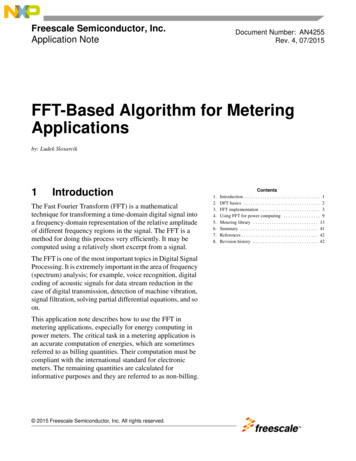
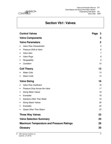
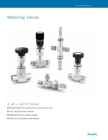
2Needle and Metering ValvesFeaturesLow-Pressure Valves (S, M, and L Series) Straight-pattern flow coefficients (Cv) from 0.004 to 0.16 Straight, angle, cross, and double patterns Panel mounting Knurled, round, vernier, slotted, and adjustable-torque handles Swagelok tube fitting, male NPT, and integral VCR fittingend connectionsTechnical aturePressure F ( C)psig (bar)–10 to 400S(–23 to 204)M—fluorocarbonFKM O-rings;–10 to 300(–23 to 148)LStemTaperOrifice Shutoff (Includedin. (mm) Service Angle)0.0322000 (137)(0.81)0.0561000 (68.9)➀—Buna NO-rings(1.42)0.128(3.25)Stem threadsare isolated fromsystem fluidLock screw“locks in” flowsettings (knurled andslotted handles) Forged-body 316 SS or brass constructionNo1 No3 Yes➁6 Guide O-ringenhances stemalignment(S series only)Handle stophelps preventdamage to stemand orificeTapered stem tipaccurately controls gasand liquid flow ratesStem O-ringcontains systemfluidS, M, and L SeriesS series valve shown.➀ Downstream pressure 500 psig (34.4 bar) max when valve requiresadjustment at pressure due to strength limitations of the fine-pitch threadsand high operating torque.➁ Stainless steel L series valves are not recommended for shutoff in vacuumor gas service, or for repetitive shutoff in liquid service.High-Pressure Valves (31 Series) Flow coefficient of 0.04; orifice of 0.062 in. (1.6 mm)S / M / L / 31SERIESMETERING 316 SS bar stock body Straight and angle patternsPacking nutpermits simpleexternaladjustment Metal-to-metal shutoff 2 stem taper (included angle) Panel mounting Round phenolic handle Swagelok tube fitting and female NPT end connectionsPressure-Temperature RatingsRatings based on optional Grafoil packing.Packingfully contained by316 SS glands toprevent extrusion440C SSregulating stemhardened forenhancedservice lifeMetal-to-metalshutoffRatings limited to 450 F (232 C) at 3435 psig (236 bar) withstandard PTFE packing.ASME Class2080Material Group2.2Material Name316 SSTemperature, F ( C)–65 (–53) to 100 (37)200 (93)300 (148)400 (204)450 (232)500 (260)600 (315)650 (343)700 (371)750 (398)800 (426)850 (454)Working Pressure, psig (bar)5000 (344)4295 (295)3875 (266)3560 (245)3435 (236)3310 (228)3130 (215)3080 (212)3000 (206)2930 (201)2880 (198)2815 (193)31 SeriesTapered stem tipaccurately controlsgas and liquid flowrates
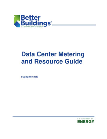
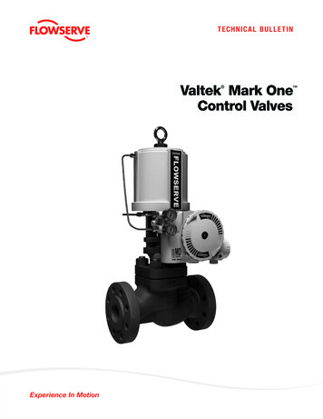
Metering Valves—S, M, L, and 31 Series3Materials of ConstructionHigh-Pressure Valves (31 Series)Low-Pressure Valves (S, M, and L Series)11a1b2231a242879S Series38547Handle screwLock screw➀1b HandleHandle screw965799M Series10L SeriesPanel mount nut3Bonnet sleeve4Bonnet5Stem guide ring6Body extension➁7Body seal➂8StemO-rings9BodyLubricants316 SSMaterial Grade/ASTM SpecificationSilver-mist chrome-plated300 SS/A276brass 360/B16Black oxide and light oil-coatedalloy steel/ANSI 18.3Green anodized aluminum 6061-T651/B211Black oxide and light oil-coated alloy steel/ANSI 18.3Silver-mist chrome-platedbrass 360/B16316 SS/A479—S, M;316 SS/B783—LSintered 316 SSSilver-mist chrome-platedbrass 345/B453316 SS/A479Buna NS17400 SS/A564—S;316 SS/A479—M, LBuna N316 SS/A479Fluorocarbon FKMHard chrome-platedS17400 SS/A564—S;Hard chrome-plated316 SS/A479—M, LFluorocarbon FKMSilver-mist chrome-platedbrass 377/B283316 SS/A182Molybdenum disulfide-based; silicone-basedMaterial Grade/ASTM Specification1 HandlePhenolic/D4617Set screwNickel-cadmiumplated steel2 Packing nut3 Upper gland316 SS/A2764 PackingPTFE/D17105 Lower gland316 SS/A2766 Stem440C SS/A2767 Panel nut316 SS/B7838 Union nut316 SS/A2769 Bonnet10 BodyGlass-filled PTFESilver-mist chrome-platedbrass 345/B453ComponentLubricant316 SS/A479Nickel antiseize withhydrocarbon carrierWetted components listed in italics.➀ Anaerobic-type adhesive.➁ Straight and double-pattern M series valves.➂ Angle and cross-pattern M series valves do notcontain a body seal.TestingCleaning and PackagingEvery Swagelok S, M, and L series metering valve is factory testedwith nitrogen at 1000 psig (69 bar). Shell testing is performed to arequirement of no detectable leakage with a liquid leak detector.Swagelok metering valves with VCR end connections areprocessed in accordance with Swagelok Special Cleaning andPackaging (SC-11) (MS-06-63), to ensure compliance with productcleanliness requirements stated in ASTM G93 Level C.Every Swagelok L series metering valve is tested for bubbletight seat shutoff at 100 psig (6.8 bar) differential pressure.Every Swagelok 31 series needle valve is factory testedwith nitrogen at 1000 psig (69 bar). Seats have a maximumallowable leak rate of 0.1 std cm3/min.Swagelok metering valves with other end connections areprocessed in accordance with Swagelok Standard Cleaningand Packaging (SC-10) (MS-06-62),; special cleaning andpackaging are available as an option.S / M / L / 31SERIESMETERING2568Valve Body Materials1a Handle484BrassComponent3
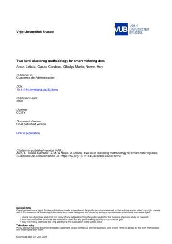
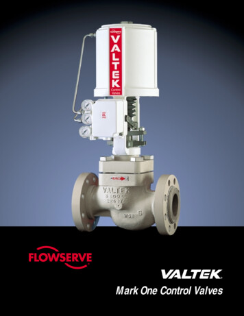
4Needle and Metering ValvesFlow Data at 70 F (20 C)Ordering InformationS SeriesSelect an ordering number.S, M, and L SeriesMaximum Flow—0.004 CvFlow Coefficient (Cv)Flow Coefficient at Turns OpenPressureDrop toAtmospherepsi (bar)Air Flowstd ft3/minWater FlowU.S. gal/min(std L/min)(L/min)10 (0.68)0.04 (1.1)0.01 (0.03)50 (3.4)0.10 (2.8)0.02 (0.07)100 (6.8)0.20 (5.6)0.04 (0.15)Factory Flow SettingNumber of Turns OpenThe handle stop is set at 4 to 10 stdcm3/min with 15 psig (1.0 bar) inletpressure.Straight PatternEGpanelholeANAdjusting stop to lower flow settingcan damage valve and stem tip.SWAGELOKM0,0040Series0,0035BMaximum Flow—0.03 CvFlow Coefficient at Turns Open0,0030Flow Coefficient (Cv)Example: B-SS1SWAGELOK For brass S, M, and L series valves,replace SS with B.0,00250,00200,00150,00100,0005PressureDrop toAtmospherepsi (bar)Air Flowstd ft3/min(std L/min)(L/min)10 (0.68)0.33 (9.3)0.09 (0.34)50 (3.4)0.90 (25.4)0.21 (0.79)100 (6.8)1.5 (42.4)0.30 (1.1)EUROWater FlowU.S. gal/minM series valve shown.S series—0.16 in. (4.1 mm) maximum panelthickness.M and L series—0.13 in. (3.3 mm) maximum panelthickness.31 SeriesFor angle-pattern 31 series valves, add-A to the ordering number.Number of Turns OpenStraight PatternL Series0.180Flow Coefficient (Cv)1.38Maximum Flow—0.16 CvFlow Coefficient at Turns Open(35.1)PressureDrop toAtmospherepsi (bar)Air Flowstd ft3/min(std L/min)(L/min)0.08010 (0.68)2.0 (56.6)0.51 (1.9)0.0600,0300.04050 (3.4)6.4 (181)1.2 (4.5)100 (6.8)11.4 (323)1.7 (6.4)0.1600.1400.1200.1000.0200,02500,020 00,0152468Water FlowU.S. gal/min0.38 (9.6)max panelthickness3.60(91.4)open0.59 (15.0)panel hole10Number of Turns Open1.09(27.7)0,01031 0,005SeriesMaximum Flow—0.04 CvFlow Coefficient at Turns OpenFlow Coefficient (Cv)S / M / L / 31SERIESMETERINGExample: SS-31RS4-APressureDrop toAtmospherepsi (bar)0,180Air Flowstd ft3/min(std L/min)BWater FlowU.S. gal/min(L/min)0,16010 (0.68)0.45 (12.7)0.12 (0.45)0,14050 (3.4)1.2(33.9)0.28 (1.0)100 (6.8)2.1(59.4)0.40 (1.5)0,1200,1000,0800,060Number of Turns Open0,0400,02000246810AB0.38(9.6)
Metering Valves—S, M, L, and 31 SeriesDimensionsDimensions, in inches (millimeters), arefor reference only and are subject tochange.Angle PatternEAEnd ConnectionsInlet/Outlet SizeDimensions, in. (mm)OrderingNumberABDES series straight pattern1/16 in. SS-SS11.56 (39.6)1/8 in. SS-SS21.90 (48.3)Swagelok1/4 in. SS-SS42.04 (51.8)tube fittings0.382.34 (59.4) 1.90 (48.3)—3 mm SS-SS3MM(9.6)6 mm SS-SS6MM2.04 (51.8)Male VCR1/4 in. SS-SVR42.06 (52.3)fittings1/16 in.Swagelok 1/8 in.tube fittings 1/4 in.3 mmMale NPT/Swagelok 1/8 in.tube fittingGpanelholeN1/8 in.Swagelok 1/4 in.tube fittings 3 mm6 mm1/8 in.Male NPT1/4 in.Female NPT 1/8 in.Male VCR1/4 in.fittingsDBSwageloktube fittingsMale NPT1.38Male NPT/Swagelok 1/8 in.tube fittingFemale NPT 1/8 in.(35.1)0.38 (9.6)max panelthicknessHopen0.59 (15.0)panel holeDB2(9.6)CM series straight patternSS-2MG2.02 (51.3)SS-4MG2.20 (55.9)SS-3MG-MM2.02 (51.3)SS-6MG-MM2.20 (55.9)2.78 (70.6) 1.50 (38.1)SS-2MG2SS-4MG2SS-2MG41.96 (49.8)1.94 (49.3)SS-MGVR42.06 2series angle pattern3.30 (83.8)1.013.39 (86.1)1.103.30 (83.8)1.013.39 (86.1)1.103.04 (77.2)0.753.27 (83.1) 0.98 )0.50(19.1)(12.7)1.02 (25.9)3.04 (77.2) 1.01 (25.7) 0.75 (19.1)SS-2MA43.26 (82.8)0.97 (24.6)1/4 in.SS-4LA6 mmSS-6LA-MMEnd ConnectionsTypeSizeOrderingNumberMale NPT—SS-2MA11/4 in.3/8 in.6 mm1/4 in.Swageloktube fittings0.45(11.4)0.98 (24.9)L series straight patternSS-4L2.34 (59.4)SS-6L2.46 (62.5)2.82 (71.6)SS-6L-MM2.34 (59.4)SS-4L22.00 (50.8)—L series angle patternSwageloktube fittingsSwageloktube fitting0.38SS-SM2-S2-A 3.07 (78.0)0.88 (22.4)(24.9)(25.9)0.99 (25.1)NB1FemaleNPT1/4 in. SS-31RS46 mm SS-31RS6MM1/8 in. SS-31RF21/4 in. SS-31RF43.77 (95.8)AB31 series1.17 (29.7)Dimensions, in. .00(25.4)Dimensions shown with Swagelok tube fitting nuts finger-tight.1.54(39.1)1.28 (32.5)3.80(96.5)S / M / L / 31SERIESMETERINGAngle Pattern1/8 in.1/4 in.3 mm6 mm1/8 in.1/4 in.S series angle patternSS-SS1-A3.22 (81.8) 0.81 (20.6)SS-SS2-A3.32 (84.3)0.98SS-SS4-A3.36 (85.3)1.02SS-SS3MM-A 3.32 (84.3) 0.98 (24.9)G5
6Needle and Metering ValvesOptions and AccessoriesECross PatternS and M SeriesGpanelhole Fluid flows between side portsaround stem in any stem position.A Flow through branch port can bemetered in both directions.NDBS series valve shown.EDouble PatternS and M SeriesGpanelhole Inlet valve handle can be set andlocked at desired maximum flow.A Outlet valve handle can be used forfine flow control up to the presetmaximum of the inlet valve.S / M / L / 31SERIESMETERINGNM series valve shown.BOrdering Information and DimensionsSelect an ordering number. For brass valves, replace SS with B.Example: B-SS2-XDimensions are for reference only and are subject to change.ValvePatternEnd ConnectionsTypeSizeCvOrderingNumberDimensions, in. (mm)ABDEGN0.38 (9.6)0.45 (11.4)0.92 (23.4)0.50 (12.7)0.58 (14.7)S seriesCrossDoubleSwageloktube fitting1/8 in.0.004SS-SS2-X3.32 (84.3)1.96 (49.8)0.98 (24.9)1/8 in.0.003SS-SS2-D2.34 (59.4)1.90 (48.3)—Swageloktube fitting1/4 in.0.03SS-4MX3.39 (86.1)1/4 in.0.026SS-4MGD2.78 (70.6)M seriesCrossDoubleDimensions shown with Swagelok tube fitting nuts finger-tight.1.10 (27.9)2.20 (55.9)—1.07 (27.2)1.56 (39.6)
Metering Valves—S, M, L, and 31 Series7Options and AccessoriesVernier HandleAdjustable-Torque HandleSlotted HandleS, M, and L SeriesS SeriesS and M 2)openopenM series valve shown.Dimensions, in inches (millimeters), are for reference only and are subject to change. Helps ensure repeatable flow Enhances control for setting flows.adjustments. Features PTFE packing and two top- Provides readings accurate tomounted torque adjustment screws.1/25 turn. Is available in stainless steel material o order, add -VH to an S seriesTordering number or -MH to an M or Lseries ordering number.on stainless steel valves and inchrome-plated brass on brassvalves, as standard.Examples: SS-SS1-VHSS-2MG-MHTo order, add -OH to the orderingnumber.Vernier Handle KitsExample: SS-SS1-OHKits contain all parts necessary to adda vernier handle to an existing valve.Adjustable-Torque Handle KitsSMLKit Ordering NumberNY-5K-SValve MaterialStainless steelBrass Is for use in installations wherehandle is not easily accessible. Is available in stainless steel materialon stainless steel valves and inchrome-plated brass on brassvalves, as standard. Allows valve to be panel mountedwithout removing handle.Kits contain all parts necessary toadd an adjustable-torque handle to anexisting valve.NY-2M-K6screwdriver.Kit Ordering NumberSS-5K-S-OHB-5K-S-OHTo order, add -SL to the orderingnumber.Example: SS-SS1-SLDimensions, in. (mm)SeriesABS1.42 (36.1)0.38 (9.6)M1.22 (31.0)0.50 (12.7)Slotted Handle KitsKits contain all parts necessary to adda slotted handle to an existing valve.Colored Handles31 SeriesBlack phenolic handles arestandard. To order coloredphenolic handles, add ahandle color designator tothe ordering number.Example: SS-31RS4-BLHandle ColorDesignatorKit Ordering ed-RDYellow-YWHandle KitsHandle kits contain handle, brass insert, and instructions.To order a black phenolic handle, use kit ordering numberPH-5K -14K-BK.For colored phenolic handles, replace -BK in the kit orderingnumber with a handle color designator.Example: PH-5K-14K-BLSeriesBlueS / M / L / 31SERIESMETERINGSeries Allows flow setting adjustment with a
8Needle and Metering ValvesOptions and AccessoriesStem O-Ring MaterialsSpecial Cleaning and Packaging (SC-11)S, M, and L SeriesAll SeriesBuna N O-rings are standard for brass valves; fluorocarbonFKM O-rings are standard for stainless steel valves. Whenordering optional stem O-ring materials:Swagelok metering valves with VCR end connections areprocessed in accordance with Swagelok Special Cleaningand Packaging (SC-11) (MS-06-63), to ensure compliancewith product cleanliness requirements stated in ASTM G93Level C. S series—stem and guide O-rings are replaced with theoptional material, except for the Kalrez option; for Kalrezmaterial, the stem O-ring is replaced and the guide O-ringremains the standard material. S series and M series—body seal material may change, asshown in the table below.O-RingMaterialDesignatorBuna ZNeoprene-NETo order special cleaning and packaging for metering valveswith other end connections, add -SC11 to the val
or gas service, or for repetitive shutoff in liquid service. S, M, and L Series S series valve shown. High-Pressure Valves (31 Series) Flow coefficient of 0.04; orifice of 0.062 in. (1.6 mm) 316 SS bar stock body Straight and angle patterns Metal-to-metal shutoff 2 stem taper (included angle) mPnea ngounl i t Round phenolic handle Swagelok tube fitting and female NPT end connections Pressure .