Transcription
BBAA VI International Colloquium on:Bluff Bodies Aerodynamics & ApplicationsMilano, Italy, July, 20-24 2008SURFACE FLOW AND WAKE STRUCTURE OF A REAR VIEWMIRROR OF THE PASSENGER CARJeong-Hyun Kim , Yong Oun Han , Min Hwa Lee , In Ho Hwang†, and Ui Hun Jung† School of Mechanical EngineeringYeungnam University, Gyeongsan, Gyeongbuk 712-749, Koreae-mail: davidkim@ynu.ac.kr, yohan@yu.ac.kr, 337056@hmd.co.kr†Technical Research LaboratorySL Corporation, Gyeongsan, Gyeongbuk 712-837, Koreae-mails: inhohwang@sl.co.kr, uihun@sl.co.krKeywords: Rear View Mirror, Wake Flow, Surface Pressure, Hot Wire Anemometry, OilFilm Visualization, Vortex EnvelopAbstract. In order to investigate the wake structure and the vortex body frame interactionnear the real scale rear view mirror of a passenger car, the velocity vector fields in wake andpressure distribution over the mirror skin have been measured by use of the hot-wire anemometry and the pressure scanning system, respectively in the blow down wind tunnel at theReynolds number of 2.5 105 . The boundary layer flow over the mirror housing and the mirror surface was visualized by the oil film technology as well. The vertical velocity vectorfields to the main stream in the mirror wake showed that within the half distance of the mirrorspan the recirculation zone appeared and the intrinsic vortex was shed with the frequency of19.6 Hz, and also showed that a conical envelop of the vortex sheet was developed with itscenter trailing towards the body frame. The minimum pressure zone on the mirror surfaceappeared near the upper tip corner, which seemed to be the origin of the vortex envelop. Theseparation focus was found on the upper tip face of the mirror housing and a surface separation line was also distributed over the edge line of the mirror housing in the visualization results. Such flow characteristics of the single mirror were compared to those of the mountedmirror to the real scale car as well.1
Jeong-Hyun Kim, Yong Oun Han, Min Hwa Lee, In Ho Hwang and Ui Hun Jung1INTRODUCTIONStreamlined body design in a passenger car helps reducing the aerodynamic drag and eventually improves the engine mileage. On the contrary, accessories attached on the body skin ofa car cause the unfavorable aerodynamic effects. The rear view mirror either side of a driveror an accompanier is one of unfavorable aerodynamic examples. In order to obtain the rearsight, unfortunately the mirror does not pay only the aerodynamic penalty which increasesbody form drag, but also causes the acoustic noise and the mirror fluctuation to the cabincrews. While the aerodynamic body styling of the passenger car has been concerned with considerable efforts, rather ignored have been defects caused by such accessory, the rear viewmirror. The main stream meets a side flow which has the flow direction tangent to the windshield surface near the A-pillar. And a conical vortex sheet is generated along the pillar andmerges into the main stream. Therefore, very complicate flow pattern appears by combiningthese flow patterns near the driver side window. Moreover, since the side mirror is mountedon the driver door near hinge, the wake flow behind this obstacle become much complicated[1] [2]. When the vehicle has a negative yaw angle, defined as the rear view mirror is in a leeward situation relative to the vehicle, the A-pillar vortex changes considerably, and large gradients in mean velocity and turbulent intensity are apparent. It gives the worst circumstance toinduce aerodynamic noise easily [3].The rear view mirror as one of blunt obstacle generates an intrinsic periodic wake patternwhich composes several vortex wraps depending on its geometry. Such a spatially periodicwake causes an intrinsic acoustic noise as well as a flow induced vibration making the mirrorsurface tremble resulting unclear vision to the driver. Worse thing happens when such periodic vortex wraps breaks down making vortex body frame interaction noise (VBIN). Therefore, it could be a good strategy to make the vortex trail not meet the door panel as possibleby path control [4] [5].One of the intrinsic noises was experienced in the mirror mount. When the transition to turbulent boundary layer over the mirror housing is not complete, pressure fluctuations can causerapidly changing flow patterns generating whistle sound to the driver. This noise can be detected near the gap between the mirror housing and the mirror mount. It is known that heavysurface graining, bumps and grooves on the mirror surface or the mount are effective to reduce whistle noise by promoting the turbulent boundary layer easily on these devices [6].Another intrinsic noise is also generated by the mount device. There are two basic configuration of rear view mirror, door mounted mirror and sail-panel mounted mirror, respectively.Intrusion of the mirror support in sail-panel mounted mirror deflects approaching flow alongthe body and eventually forms a disk-like vortex underneath the mirror housing. It causes astrong vortex shedding, which stimulates instability within the body frame shear layer [7].There have been observed typical strategies to reduce such the traditional problems of therear view side mirror as noise and mirror surface vibration. Geometric shape of the mirrorhousing should be primarily concerned to reduce the strength of intrinsic shedding vortex aspossible, such as elimination of sharp edges on all corner, tube typed extension of the mirrorhousing which keeps away the flow recirculation [8]. As another strategy, the path control ofvortex wrapped sheet could be used to put away from the door window or panel by changingthe mounting location in order to avoid VBIN.In this paper, the wake structure of the rear view mirror and the pressure profile over boththe mirror housing and the mirror surface will be measured directly to understand the flowstructure and its interference to the body of the passenger car with the real scale side mirror.Also the path control of the vortex trail generated by the rear view mirror will be observedbased on data obtained.2
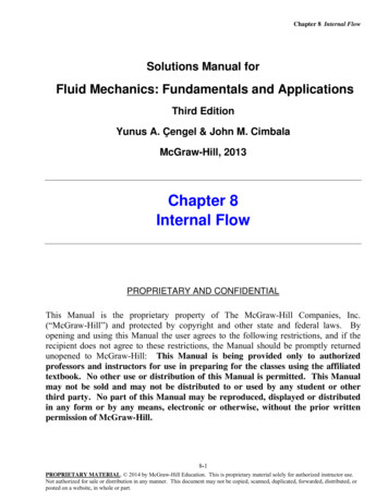
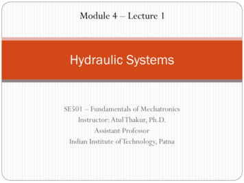
Jeong-Hyun Kim, Yong Oun Han, Min Hwa Lee, In Ho Hwang and Ui Hun Jung2DESCRIPTION OF THE EXPERIMENTA blow down type wind tunnel which has the dimension of 0.9 0.7 2.0 [m] was used tomake parallel flow around a real scale rear view mirror only. To observe the body frame interaction of the mirror wake, one of the side walls of the wind tunnel test section was modified to fit to the driver side skin of the real scale car by locating the mirror center mounted onit at the test section center of the wind tunnel. The real scale mirror of New Pride manufactured by KIA motor Korea was chosen for the experiments of both the single model whichused the real scale mirror and mounting zig only and the real scale model which mounted onthe real scale car. The experimental set up of the mirror in the test section is shown in figure 1.(a)(b)Figure 1: Photographs of the rear view mirror installed in the test section of the wind tunnels for (a) the singlemodel and (b) the mounted model, respectively.For convenient experiment, a pressure model was fabricated by using the composite material under RP process. Figure 2 shows the real scale pressure model. Static pressure holeswere made with 0.8 [mm] diameter at 135 points over the housing surface and at 137 pointson the mirror surface, respectively. The space between two holes on the mirror surface was10[mm] horizontally and vertically. Each hole was connected by tubing to the pressure transducer with the scanni-valves. The analog signal measured by pressure transducers was digitized by 16 bit A/D converter and it was stored in personal computer.RootTipFigure 2 : The real scale pressure model3
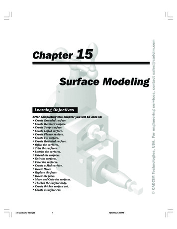
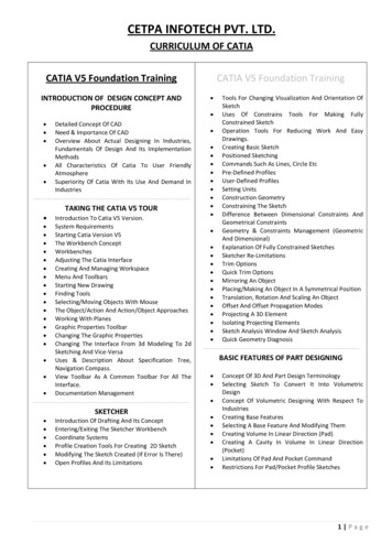
Jeong-Hyun Kim, Yong Oun Han, Min Hwa Lee, In Ho Hwang and Ui Hun JungTo obtain the velocity vector field of the wake, the x-configuration hot wire was utilized.Wake velocity fields were measured at the several vertical sections to the main flow direction.In recirculation zone of the wake behind the mirror the two dimensional LDV system used toget the negative velocity.To visualize the movement of the surface vortex on the boundary layer over the mirrorhousing surface including the mounting device and the mirror surface, an oil film visualization technique was utilized. This oil film technique was also used to observe the body frameinteraction of the vortex wrap generated by the mirror by tracing where the oil left from themirror arrives over the body frame.33.1RESULTS AND DISCUSSIONPressure distributionStatic pressure profiles over the surface of the mirror housing were obtained along the geometric latitude lines; middle span which is most convex, upper span where the housing hasalmost right turn to the main flow direction, and lower span where the housing has mild turnto the main flow, and three vertical lines. Figure 3 shows representation of data points overthe surface of mirror housing. Plots of pressure distribution for the speed of 25[m/s] areshown in the figure 4. Pressure distribution has the peak near the mounting root even thoughthe whole housing front was inclined as 30 degrees to the main flow. Vertical profile of thetotal pressure at the middle line shows mild peak at the little upward position which matcheswell to the housing contour. These profiles were not changed even when the single mirrormodel was mounted to the real car.Figure 3 : Representation of data points over the surface of mirror housing.(a)(b)Figure 4 : Pressure distributions over the surface of mirror housing measured on (a) the middle span line and (b)the middle vertical line, respectively.4
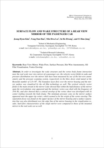
Jeong-Hyun Kim, Yong Oun Han, Min Hwa Lee, In Ho Hwang and Ui Hun JungConsiderable static pressure measurement was carried out over the whole mirror surfaceusing 137 static holes. Figure 5 shows static pressure distributions on the mirror surfaces bothsingle and mounted models, respectively. It is important where the minimum static pressurelocates because the origin of the vortex sheet wrap may be considered to locate at the minimum point. The minimum pressure appeared near upper root corner for the single model, butit was shown up lower tip region for the case of the mirror mounted to the real car. Based onthis observation, this mirror was optimized geometrically to induce the vortex center locatedfar from the car body, which is the one of main objectives to control the path of the vortexwrap.(a)(b)Figure 5 : Pressure distributions on the mirror surface for (a) the single model and (b) the mounted model.3.2Wake structureTo find the wake structure behind the rear view mirror, the velocity vector fields were obtained on the vertical planes; 0.5d, 1.0d, 1.5d and 2.0d (d is based on the span length of themirror) downstream to the main flow direction by using the x-configuration hot wire and 2-DLDV system. The mirror surface was inclined with 30 degrees for the driver to retain the rearview to the main direction, note that the test sections were not arranged as parallel to the mirror surface.Figure 6 : Contour plot of the axial velocity measured by LDV system for the single model with the inflow velocity of 25 [m/s].5
Jeong-Hyun Kim, Yong Oun Han, Min Hwa Lee, In Ho Hwang and Ui Hun JungFrom the test results until downstream at 1.0d there appeared recirculation zone in the axialflow velocity components which was observed by the smoke visualization. LDV result showsthe recirculation area in the U-contours as shown in the figure 6.Figure 7 shows the two-dimensional time-averaged vector fields for the single model. Thevortex pair was found to form at a mounting zig and then moved towards tip region in downstream. Also, vortex center generated on the root region of the mirror surface moved in thesame direction during this process. The vertical velocity fields show the strong upwash velocity behind the neck of the mirror.(a)(b)(c)(d)Figure 7 : Vertical velocity vector fields for the single model measured at the vertical section of (a) 0.5d (b) 1.0d(c) 1.5d and (d) 2.0d downstream to the main flow with the inflow velocity of 25[m/s].The corresponding axial vorticity fields at various downstream locations are plotted asshown in figure 8. The strong vorticity was shown behind upper root corner of the mirror including vortex pair induced from a mounting zig. The location of the maximum axial vorticitygradually moved towards tip region in downstream. These results show that influence of con-6
Jeong-Hyun Kim, Yong Oun Han, Min Hwa Lee, In Ho Hwang and Ui Hun Jungtraction between side face of the mirror and mounting zig was dominant in wake flow for thesingle model.(a)(b)(c)(d)Figure 8 : Vorticity contour plots for the single model at the vertical section of (a) 0.5d (b) 1.0d (c) 1.5d and (d)2.0d downstream to the main flow with the inflow velocity of 25[m/s].Wake survey results for the mounted model from the x-configuration hot-wire anemometryare shown in figure 9 and 10. Figure 9 shows the time-averaged vector fields for the mountedmirror on the vertical planes; 0.5d and 2d, respectively. Compared with the single model, different wake structure was found for each section. A vortex center was formed behind tip region of the mirror surface and moved more adjacent to the body skin creating a large rotatingvortex in the downstream of the model. With the inflow velocity increase the vortex sheetwrap was found to come closer to the body frame which may result in the increase of noise.The vertical velocity vector fields show vortex sheet wraps in downstream which does notonly explain how frequently the periodic conical vortex sheet appears in the downstream direction, but also shows where the path of the vortex center establishes.The corresponding vorticity plots are shown in figure 10. Strong vorticity was shown behind the housing edge of the mirror at the vertical section of 0.5d downstream and it was observed near the body frame at the vertical section of 2d downstream because of a counterrotating vortex.7
Jeong-Hyun Kim, Yong Oun Han, Min Hwa Lee, In Ho Hwang and Ui Hun Jung(a)(b)(c)(d)Figure 9 : Vertical velocity vector fields for the mounted model measured at the vertical section of (a) 0.5d and(b) 2.0d downstream to the main flow with the speed of 10[m/s] and (c) 0.5d and (d) 2.0d downstream to themain flow with the speed of 25[m/s].3.3Surface flow visualizationTo look into details for such vortex wrap control on the boundary layer, streamline overboth the housing and mirror surfaces must be observed. For this purpose the oil film techniquewas utilized for dynamic visualization over the mirror skin in both the single model and themounted model with the inflow velocity of 25[m/sec]. Figure 11 shows a flow pattern of oilfilm surface for the single mirror. The nodal attachment point was observed near the root ofthe housing surface because rear view mirror had a yaw angle to a mounting zig. Surface flowspread out over the housing surface from that point and formed a separation line at a little bitahead the edge line of the housing, which explains the lower pressure zone was establishedbefore the apex line in the boundary layer flow. A huge separation focus appeared at the uppercorner on the mirror housing near the tip region. On the mirror surface, the surface streamlinewas tended to make circle in clockwise direction. This implies that the lower pressure zone8
Jeong-Hyun Kim, Yong Oun Han, Min Hwa Lee, In Ho Hwang and Ui Hun Jungappeared near the root corner. Therefore, oil film visualization may be used to expect thepressure distribution on the mirror surface in the future work.(a)(b)(c)(d)Figure 10 : Vorticity contour plots for the mounted model at the vertical section of (a) 0.5d and (b) 2.0d downstream to the main flow with the speed of 10[m/s] and (c) 0.5d and (d) 2.0d downstream to the main flow withthe speed of 25[m/s].Figure 11 : Surface flow visualizations for the single model.9
Jeong-Hyun Kim, Yong Oun Han, Min Hwa Lee, In Ho Hwang and Ui Hun JungCompared with results of the single model, the mounted mirror model showed differencefor the location of the separation and the minimum pressure zone. Figure 12 shows that theseparation focus was become weaker and drifted toward to the tip face so that it implies theresultant strength of the vortex wrap generated by the mirror housing becomes favorable forthe vortex control. On the mirror surface, the surface streamline was tended to make circle incounter clock wise direction, implying the lower pressure zone appeared near the tip cornerand therefore, forming the vortex center at the upper tip corner on the flat mirror surface. Inaddition, we found that flow separated from the lower tip face arrived over the body frame.These results show the consistency to the vertical velocity vector measurements.Figure 12 : Surface flow visualizations for the mounted model.3.4Shedding frequency estimationTo estimate the shedding frequency in the wake of the mirror, a commercial code was usedto calculate the periodic characteristics generated by the Karman vortex. Figure 13 shows periodic characteristics of the static pressure on the mirror surface in the condition on the inflowvelocity was 25[m/sec]. As shown in the figure 13, the shedding frequency of the alternatingvortices was seemed to be about 19[Hz], calculated by Fluent.Generally, it is known that the frequency of the alternating vortices is proportional to inflow velocity for the given Strouhal number. Therefore, in the realistic flow velocity range;25 40[m/s], corresponded to be 90 144[km/h], the shedding frequency aroused by such scalemirror seems to be ranged in 20 30[Hz]. This result gives the useful information to find theacoustic noise source generated by the mirror housing in VBIN problem.Figure 13 : Time history of static pressure fluctuation on the mirror surface10
Jeong-Hyun Kim, Yong Oun Han, Min Hwa Lee, In Ho Hwang and Ui Hun Jung3.5ComparisonsThrough various measurements the flow structure around rear view mirror has been unveiled. Around the rear view mirror the intrinsic vortex is shedding across the vertical mirrorsurface and the resultant vortex wrap in the wake is also formed. The geometric shape of themirror housing must be designed to reduce the vortex strength as well as the vortex pathshould be away from the body as possible. In this experiment it was turned out the trail of thevortex sheet wrap generated by such a bluff body tends to meet the body skin of a car, arousing the vortex-body frame interaction. The co-ander effect seems to accelerate such interference. This requires the path control for the vortex drift should consider rigorously more thanexpected.It was also found that the boundary layer structure of the single model shows many differences from those of the mounted mirror. This implies that there exists any possibility to makea misleading for the flow structure by observing only those of the single model when notlooking into the interaction. The pressure distribution and the visualization show their differences clearly.4SUMMARYObserving the flow structure around the rear view side mirror of a passenger car by the hotwire anemometry, pressure measurement and oil film visualization, it can be summarized asfollows ;The flow around the mirror model mounted on the real car shows much different fromthose of the single model specially on the position of the minimum pressure location on themirror surface, and the separation focus as well; the minimum pressure appeared at the lowertip region for the mounted model while it was at the upper root region for the single model,and the weaker separation focus of the mounted was located on the vertical tip face while thatof the single model was on the top corner, respectively.With the inflow velocity increase the vortex sheet wrap comes closer to the body framewhich caused the interaction and resulted in the noise increase. The trail of the vortex centershows more adjacent to the body skin than expected, which implies that the co-ander effectwas prevailed.Based on the vertical velocity vector fields the vortex strength was attenuated as much asan half of that of the 0.5d plane within 2.0d. It turned out that the intrinsic vortex sheddingwas not much affected to the body frame interference, but to the vibration of mirror surface,while the vortex sheet wrap affects strongly the interaction noise in downstream.ACKNOWLEDGEMENTSThis work was supprted by SL Corporation, Korea. Their supports are greatly acknowledged.REFERENCES[1] W. Hucho, Aerodynamics of Road Vehicles 4th edition, Society of Automotive Engineers, Inc., 1998.[2] K. Ono, R. Himeno, T. Fukushima, Prediction of wind noise radiated from passengercars and its evaluation based on auralization, Journal of Wind Engineering and Industrial Aerodynamics, 81, 403-419, 1999.11
Jeong-Hyun Kim, Yong Oun Han, Min Hwa Lee, In Ho Hwang and Ui Hun Jung[3] S. Watkins, On The Causes of Image Blurring in External Rear View Mirrors, SAE Papers 2004-01-1309, SP-1874, Detroit, Michigan, USA, March 2004.[4] Y. O. Han. Research for the Low Noise Rear View Side Mirror of a Passenger Car,Report of Aerodynamic & Turbulence Research Laboratory, 2007-05, May 2007.[5] Y. O. Han, J. H. Kim, I. H. Hwang, J. B. Seo, B. H. Lim and U. H. Jung. Wake FlowCharacteristics around the Side Mirror of a Passenger Car, KSME Conference, BEXCOBuilding, Busan, Korea, 30 May-1 June, 2007.[6] T. Lounsberry, M. Gleason and M. Puskarz, Laminar Flow Whistle on a Vehicle SideMirror, SAE Paper 2007-01-1549, V 116-6, Detroit, Michigan, USA, April 2007.[7] O. Dolek, G. Ozkan and I. B. Ozdemir, Structures of flow around a full scale side mirror of a car with relevance to aerodynamic noise, Journal of Automobile Engineering,Volume 218 Number 10, 1085-1097, 2004.[8] R. Jaitlee, F. Alam and S. Watkins, Pressure Fluctuations on Automotive Rear ViewMirrors, SAE Paper 2007-01-0899, SP-2066, Detroit, Michigan, USA, April 2007.12
To find the wake structure behind the rear view mirror, the velocity vector fields were ob-tained on the vertical planes; 0.5d, 1.0d, 1.5d and 2.0d (d is based on the span length of the mirror) downstream to the main flow direction by using the x-configuration hot wire and 2-D LDV system.