Transcription
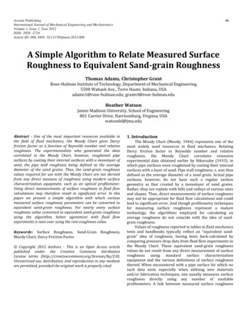
Surface Finish AnalysisApril 2 2014
Overview The Basics Equipment Measuring Conditions & Correlation Parameters Definitions Parameters and Function
Measure What?The primary metrological featuresof a surface are: Size Position Form (or Contour) Waviness Roughness
Why Measure Surface Roughness?It’s on the print ISO 9000 and QS 9000 compliance Find the bad parts Process Control
Process ControlTurning and Milling, a greatindicator of tool life Grinding, when to Redress Lapping and Honing Extrusion and Injection Molds
The Standards ASME B46.1-2002ASME Y14.36-1996Surface TextureDrawing ersFilteringPlateaued -JIS 0660-1998JIS 0651-1996JIS sDesignation
True Surface
Suppress Overall Contour
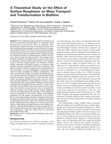
Curve Removal OriginalProfileRa 500µin Curve Removedwith λc filterresidual errorRa 35µin Curve ProperlyRemovedRa 15µin
Tilt (Inclination)CompensationBeforeAfter
Primary Profile Any curve or tilt are removed using appropriate compensation Lambda s low pass filter applied to eliminate noise
Primary Profile
Waviness Profile
Waviness Profile
Roughness Profile
Roughness Profile
The System Motorized Drive Unit with Feedback Detector Analyzer
HardwareDetectorDrive UnitAnalyzer
Skid Measurement Skid Measuring instruments are used to measure Roughness only Less prone to noise Most commonly used
The Skid The skid mechanically filters waviness
Skidless Measurement Skidless Measuring instruments are used to measure both Roughnessand Waviness No Skid means you can measure in confined areas Skidless Systems are prone to vibration
λs
Cutoff, λc, sampling length
Default Cutoff - LcRa0 - .8µ”.8 – 4µ”4 – 8080 – 400400 & -2002 3.3.20“Roughness filter cutoff length is determined in part by the x and z aspects of the surface under evaluation as relatedTo the intended function of the surface. The roughness filter cutoff length should be chosen by the designer in light of theIntended function of the surface. When choosing the appropriate roughness filter cutoff, one must be cognizant thatThe surface features not measured within the roughness cutoff bandwidth may be quite large and may affect the intendedFunction of the surface .”
Lc Filter Distortion Wrong Cutoff Right Cutoff
Pre and Post
Filter Types Gaussian50% Wavelength transmission, Digital Filter, LessError, Default 2RC 75 PCEmulated 75% pass RC filter, Phase Corrected,Prone to Gibbs 2RC 75Prone Gaussian λs 50% Digital Filter, ISO BandPass, Less Prone toStylus andEquipment Variation Gauss Spline 50% Digital Filter, ISO BandPass, Less Prone toStylusand Equipment Variation, Little or No EdgeEffectsEmulated 75% pass RC filter, Non-Phase Corrected,to Gibbs, Most common in older equipment
Terminologyn1n2Sample Length cn3n4n5Evaluation LengthLength of TravelLm c * 5Lt c * 5 cp re2 cp o st2Length of Travel is the total measured length. Commonly referred to as LtSample Length is a segment of the measured profile used in determining localized occurrences.Always equal to the cutoff length. Referred as L,lr,ln,le, but not limited to.Cutoff Length is the window size used to filter the measured profile. Always equal to the samplelength. Commonly referred to as lc, lamda c, c N is number of sampling lengths. Sometimes referenced with subscripts.Evaluation Length is total of all the sampling lengths used in an evaluation. Commonly referred to as lmPre and Post Lengths is starting and ending lengths used in filtered evaluations.A minimum of lc/2 for gaussian, lc for RC. Commonly referred as lr, start length, end length
ASPECT RATIOGraphical representations of surfaces are scaled much greater vertically than horizontallyfor the purpose of illustrating vertical deviations.Aspect ratio (Z:X) 25:1Aspect ratio (Z:X) 1:1
Stylus
Stylus
Calibration Calibrate only when needed, verify as frequently aspossibleASME says calibration is necessary if verification variesby 10% or more, if using 116uin expect 2uin on a newpatchUse High side of standard to calibrate gain, Low side toverify diamond
Equipment Correlation What most effects correlation?Setup must be exactly the same - CutoffLength, Filter Type, Stylus Radius, MeasuringSpeed, Data DensityUse the same master to calibrate allinstruments
Parameter Groups Averaging Parameters - Ra, Rq Extreme Amplitude Parameters – Rz, Rt, Rp, Rv,Ry,Wt,Pt Peak to Valley Height Single Flaw Spatial and Slope Parameters – Pc, Rdq, Sm Bearing Ratio Parameters – tp, tpi, mr, mrd, mrc Rk Family, Rpq, Rvq, Rmq Length Ratio\ Scale Parameters Lo, Lr Fractals
Ra-Average roughness of the evaluated profile
Same Surface?
Rq-Mean square roughnessMore sensitive to peaks and valleys than Ra, butless robust. Commonly referred to as RMSRq 1NN2 Z ( n) 1
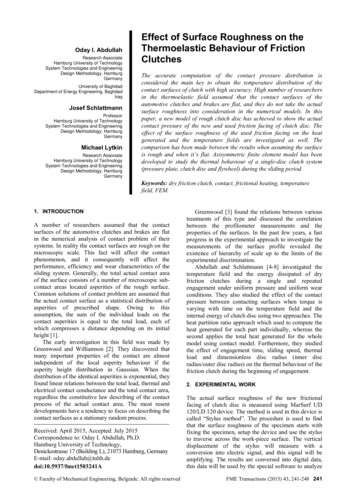
Rz- Average peak to valley height4.38um2.24um2.10um0.37um0.61um1Rz NN 5N Z ( n)max Z (n) min1 Most versatile process control parameter Very sensitive to process changes Relatively Robust Usage Milled, Turned, Ground, Lathe, Polished Surfaces Common usage for DIN/New ISO/ASME
Rz(JIS/Old ISO)-Ten point average peak to valleyheight.1 N iRz Z (i ) max Z (i ) min Ni 1 1N 5, i 5 Sensitive to process changes Robust Usage Milled, Turned, Ground, Lathe, Polished Surfaces No longer commonly used
Rc-Average peak to valley height with no limit to the amount ofpeaks and valleys1 NRc Z (n) max Z (n) minN 1N NumberofPeaks & Valleys Potential process control parameter Very sensitive to process changes Most Robust of Amplitude Parameters Possible Milled, Turned, Ground, Lathe, Polished Surfaces Not commonly used, DIN
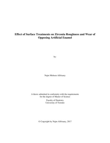
Rp- Maximum peak height1.75um3.86um0.12um0.26um1Rp NN 5N Z ( n)max1 Monitor Witness Marks / Clean-up Sensitive to process changes Usage Ground, Polished, Honed Surfaces Common usage for DIN/New ISO Rp is the single largest peak in ASME B46.11.45um
Rv- Maximum valley depth0.35um0.52um0.24um1Rv NN 5N Z ( n)0.49um0.65ummin1 Not sensitive to process changes Relatively Robust Susceptible to inherent material qualities/ porosity Great scratch identifier Usage Ground,Polished, Honed Surfaces
Ry/Rz1max-Max local peak to valley height.4.38umRy Z (n) max Z (n) minN 5 Single Flaw Parameter Very sensitive Max type
Rt-Largest peak to valley height.4.51umRt Z max Z min Very sensitive to anything Least Robust Single Flaw Parameter All Type
Bearing Area Curve (BAC) Used primarily for the analysis of load carrying surfaces A.k.a. – Wear Curve, Abbott-Firestone curve,Abbott Curve (Firestone dropped after tire problems), Tp Curve
Bearing Area Curve (BAC) A Graph of the Material Distribution Simply the cumulative distribution of the measure data points
Material RatioCutDepthValue (%)Typically a Cut is specified in %Depth in µmThe calculated Mr (tp) value is %
Htp / dcThe differences in depth between two specified percentagesReferred to as the reference depth and slice depthUsed to help guarantee a particular shaped distribution. I.e. flat
Rk Rk is the core roughness, determined by convolving a 40% line acrossthe Bearing Area Curve A three line fit used to quantify the shape of the BAC Developed for Surfaces with a strong plateau characteristic
RpkRpk Rpk is the reduced peak heigth protruding up from the core roughness Used to assure peakless surface with good break in qualities
RvkRvk Rvk is the reduced valley depth protruding down from the coreroughness Used to assure adequate valleys for liquid retention, heat dissipation,and removed material reservoirs
Material Ratio 1Mr1 Mr1is the material ratio 1 which is a measure of the amountof peaks Used to monitor peak removal
Material Ratio 2Mr2 Mr2 is the material ratio 2 which is a measure of theamount of peaks and bearing surface, exclusive of valleys Used to monitor material removal and valley volume
Vo / A2Vo Vo is a measure of valley volume Oil Retention
Pc, HSC, Sm, SC1C2 Pc - a measure of the number of peaks per cm (or inch), usedto determine texture/aesthetics/adhesion/paintability HSC – Pc with only an upper threshold Sm, S - Average Peak Spacing
Cylinder BoreRmr 75% max c 0.5um from a 5% reference line
RmrRmr 75% max c 0.5um from a 5% reference line
Custom CalloutsRz1max 120umRpmax 90umRvmax 30um2.5mm Lc12.5mm LeNo more than 3 failuresallowed per test
“Roughness filter cutoff length is determined in part by the x and z aspects of the surface under evaluation as related To the intended function of the surface. The roughness filter cutoff length should be chosen by the designer in light of the Intended function of the surface. When choosing the appropriate roughness filter cutoff, one must be cognizant that The surface features not measured .