Transcription
Living Image SoftwareUser’s ManualVersion 3.2
2002-2009 Xenogen Corporation. All rights reserved.PN 125112Caliper Life Sciences68 Elm StreetHopkinton, MA 01748USA1.877.522.2447 (US)1.508.435.9500Fax: 1.508.435.3439E-mail: ry in the Living Organism, IVIS Imaging System and Living Image are either registered trademarks ortrademarks of Xenogen Corporation. The names of companies and products mentioned herein may be thetrademarks of their respective owners. Apple, Macintosh and QuickTime are registered trademarks of AppleComputer, Inc. Microsoft, PowerPoint and Windows are either registered trademarks or trademarks of MicrosoftCorporation in the United States and/or other countries. Adobe and Illustrator are either registered trademarks ortrademarks of Adobe Systems Incorporated in the United States and/or other countries.
Living Image Software User’s ManualContents1 Welcome . . . . . . . . . . . . . . . . . . . . . . . . . . . . . . . . . . . . . . . 11.1 What’s New In the Living Image 3.2 Software . . . . . . . . . . . . . . . . . . . . . . . . . . 11.2 About This Manual . . . . . . . . . . . . . . . . . . . . . . . . . . . . . . . . . . . . . . . . 11.3 Contacting Caliper Technical Support . . . . . . . . . . . . . . . . . . . . . . . . . . . . . . . 32 Getting Started . . . . . . . . . . . . . . . . . . . . . . . . . . . . . . . . . . . . 52.1 Overview of Imaging & Image Analysis . . . . . . . . . . . . . . . . . . . . . . . . . . . . . 52.2 Starting the Living Image Software . . . . . . . . . . . . . . . . . . . . . . . . . . . . . . . 92.3 Initializing the IVIS Imaging System . . . . . . . . . . . . . . . . . . . . . . . . . . . . . . 112.4 Checking the System Temperature . . . . . . . . . . . . . . . . . . . . . . . . . . . . . . . 112.5 About the IVIS Acquisition Control Panel & Auto Exposure Feature . . . . . . . . . . . . . 123 Acquire an Image or Image Sequence . . . . . . . . . . . . . . . . . . . . . . . 153.1 Acquire a Bioluminescence Image . . . . . . . . . . . . . . . . . . . . . . . . . . . . . . . . 153.2 Acquire a Fluorescence Image With Epi-Illumination . . . . . . . . . . . . . . . . . . . . . 183.3 Acquire a Fluorescence Image With Transillumination . . . . . . . . . . . . . . . . . . . . . 193.4 Acquire an Image Sequence . . . . . . . . . . . . . . . . . . . . . . . . . . . . . . . . . . . 223.5 Manually Setting the Focus . . . . . . . . . . . . . . . . . . . . . . . . . . . . . . . . . . . . 343.6 Manually Saving Image Data . . . . . . . . . . . . . . . . . . . . . . . . . . . . . . . . . . 343.7 Exporting Image Data . . . . . . . . . . . . . . . . . . . . . . . . . . . . . . . . . . . . . . 354 Acquire Kinetic Data . . . . . . . . . . . . . . . . . . . . . . . . . . . . . . . . . 374.1 Kinetic Acquisition . . . . . . . . . . . . . . . . . . . . . . . . . . . . . . . . . . . . . . . 374.2 Viewing & Editing Data (Kinetic Acquisition window) . . . . . . . . . . . . . . . . . . . . . 424.3 Saving Data . . . . . . . . . . . . . . . . . . . . . . . . . . . . . . . . . . . . . . . . . . . 435 Working With Data . . . . . . . . . . . . . . . . . . . . . . . . . . . . . . . . . . 455.1 Browsing & Opening Data . . . . . . . . . . . . . . . . . . . . . . . . . . . . . . . . . . . . 455.2 The Tool Palette & Image Window . . . . . . . . . . . . . . . . . . . . . . . . . . . . . . . 505.3 Working With an Image Sequence . . . . . . . . . . . . . . . . . . . . . . . . . . . . . . . 515.4 Working With a Single Image . . . . . . . . . . . . . . . . . . . . . . . . . . . . . . . . . . 555.5 Viewing Image Information . . . . . . . . . . . . . . . . . . . . . . . . . . . . . . . . . . . 595.6 Image Layout Window . . . . . . . . . . . . . . . . . . . . . . . . . . . . . . . . . . . . . . 625.7 Adjusting Image Appearance . . . . . . . . . . . . . . . . . . . . . . . . . . . . . . . . . . 635.8 Correcting or Filtering Image Data . . . . . . . . . . . . . . . . . . . . . . . . . . . . . . . . 665.9 Image Information Tools . . . . . . . . . . . . . . . . . . . . . . . . . . . . . . . . . . . . . 675.10 Rendering Intensity Data in Color . . . . . . . . . . . . . . . . . . . . . . . . . . . . . . . 745.11 Viewing Transillumination Data . . . . . . . . . . . . . . . . . . . . . . . . . . . . . . . . 761
Contents5.12 Viewing & Editing Kinetic Data . . . . . . . . . . . . . . . . . . . . . . . . . . . . . . . . 776 Working With ROI Tools . . . . . . . . . . . . . . . . . . . . . . . . . . . . . . . 816.1 About ROIs . . . . . . . . . . . . . . . . . . . . . . . . . . . . . . . . . . . . . . . . . . . 816.2 ROI Tools . . . . . . . . . . . . . . . . . . . . . . . . . . . . . . . . . . . . . . . . . . . . 826.3 Measuring ROIs in an Image . . . . . . . . . . . . . . . . . . . . . . . . . . . . . . . . . . 846.4 Measuring Background-Corrected Signal . . . . . . . . . . . . . . . . . . . . . . . . . . . . 916.5 Measuring ROIs in Kinetic Data . . . . . . . . . . . . . . . . . . . . . . . . . . . . . . . . . 946.6 Managing ROIs . . . . . . . . . . . . . . . . . . . . . . . . . . . . . . . . . . . . . . . . . . 976.7 Managing the ROI Measurements Table . . . . . . . . . . . . . . . . . . . . . . . . . . . . . 1067 Image Math . . . . . . . . . . . . . . . . . . . . . . . . . . . . . . . . . . . . . 1117.1 Using Image Math to Create a New Image . . . . . . . . . . . . . . . . . . . . . . . . . . 1127.2 Subtracting Tissue Autofluorescence . . . . . . . . . . . . . . . . . . . . . . . . . . . . . 1157.3 Overlaying Multiple Images . . . . . . . . . . . . . . . . . . . . . . . . . . . . . . . . . . 1188 Planar Spectral Image Analysis . . . . . . . . . . . . . . . . . . . . . . . . . . 1218.1 Planar Spectral Image Analysis . . . . . . . . . . . . . . . . . . . . . . . . . . . . . . . . 1218.2 Planar Spectral Imaging Tools . . . . . . . . . . . . . . . . . . . . . . . . . . . . . . . . . 1238.3 Viewing & Exporting Graphical Results . . . . . . . . . . . . . . . . . . . . . . . . . . . 1258.4 Managing Planar Spectral Imaging Results . . . . . . . . . . . . . . . . . . . . . . . . . . 1269 Spectral Unmixing . . . . . . . . . . . . . . . . . . . . . . . . . . . . . . . . . 1279.1 Spectral Unmixing . . . . . . . . . . . . . . . . . . . . . . . . . . . . . . . . . . . . . . . . 1289.2 Spectral Unmixing Results Window . . . . . . . . . . . . . . . . . . . . . . . . . . . . . . . 1319.3 Spectral Unmixing Parameters . . . . . . . . . . . . . . . . . . . . . . . . . . . . . . . . . 1329.4 Spectral Unmixing Options . . . . . . . . . . . . . . . . . . . . . . . . . . . . . . . . . . . . 13410 Generating a Surface Topography . . . . . . . . . . . . . . . . . . . . . . . . 13910.1 Generate the Surface Topography . . . . . . . . . . . . . . . . . . . . . . . . . . . . . . 13910.2 Managing Surfaces . . . . . . . . . . . . . . . . . . . . . . . . . . . . . . . . . . . . . . . 14211 Point Source Fitting . . . . . . . . . . . . . . . . . . . . . . . . . . . . . . . . 14311.1 Displaying the Point Source Fitting Tools . . . . . . . . . . . . . . . . . . . . . . . . . . 14311.2 Point Source Fitting . . . . . . . . . . . . . . . . . . . . . . . . . . . . . . . . . . . . . . 14611.3 Checking the Point Source Fitting Results . . . . . . . . . . . . . . . . . . . . . . . . . . 14811.4 Exporting Results . . . . . . . . . . . . . . . . . . . . . . . . . . . . . . . . . . . . . . . 14811.5 Managing Point Source Fitting Results . . . . . . . . . . . . . . . . . . . . . . . . . . . . . 14912 3D Reconstruction of Sources . . . . . . . . . . . . . . . . . . . . . . . . . . 15112.1 3D Reconstruction of Bioluminescent Sources . . . . . . . . . . . . . . . . . . . . . . . . . 15212.2 3D Reconstruction of Fluorescent Sources . . . . . . . . . . . . . . . . . . . . . . . . . . 1562
Living Image Software User’s Manual12.3 DLIT & FLIT Results . . . . . . . . . . . . . . . . . . . . . . . . . . . . . . . . . . . . . . 15812.4 3D Tools . . . . . . . . . . . . . . . . . . . . . . . . . . . . . . . . . . . . . . . . . . . . . 16412.5 3D Tools - Mesh Tab . . . . . . . . . . . . . . . . . . . . . . . . . . . . . . . . . . . . . 17012.6 3D Tools - Volume Tab . . . . . . . . . . . . . . . . . . . . . . . . . . . . . . . . . . . . . 17212.7 3D Tools - Organs Tab . . . . . . . . . . . . . . . . . . . . . . . . . . . . . . . . . . . . 17512.8 3D Tools - Animation Tab . . . . . . . . . . . . . . . . . . . . . . . . . . . . . . . . . . . 18212.9 Managing DLIT/FLIT Results . . . . . . . . . . . . . . . . . . . . . . . . . . . . . . . . 18713 Troubleshooting Guide . . . . . . . . . . . . . . . . . . . . . . . . . . . . . . 18913.1 DLIT/FLIT Analysis Troubleshooting . . . . . . . . . . . . . . . . . . . . . . . . . . . . 189Appendix A IVIS Acquisition Control Panel . . . . . . . . . . . . . . . . . . . . . 191Appendix B Preferences . . . . . . . . . . . . . . . . . . . . . . . . . . . . . . . 195B.1 General Preferences . . . . . . . . . . . . . . . . . . . . . . . . . . . . . . . . . . . . . . . 196B.2 User Preferences . . . . . . . . . . . . . . . . . . . . . . . . . . . . . . . . . . . . . . . . . 198B.3 Acquisition . . . . . . . . . . . . . . . . . . . . . . . . . . . . . . . . . . . . . . . . . . . . 199B.4 Theme . . . . . . . . . . . . . . . . . . . . . . . . . . . . . . . . . . . . . . . . . . . . . 200B.5 Tissue Properties . . . . . . . . . . . . . . . . . . . . . . . . . . . . . . . . . . . . . . . 201B.6 3D Analysis . . . . . . . . . . . . . . . . . . . . . . . . . . . . . . . . . . . . . . . . . . 202Appendix C Detection Sensitivity . . . . . . . . . . . . . . . . . . . . . . . . . . 205C.1 CCD Detection Efficiency . . . . . . . . . . . . . . . . . . . . . . . . . . . . . . . . . . . 205C.2 Binning . . . . . . . . . . . . . . . . . . . . . . . . . . . . . . . . . . . . . . . . . . . . 206C.3 Smoothing . . . . . . . . . . . . . . . . . . . . . . . . . . . . . . . . . . . . . . . . . . . 208Appendix D Image Data Display & Measurement . . . . . . . . . . . . . . . . . . 211D.1 Image Data . . . . . . . . . . . . . . . . . . . . . . . . . . . . . . . . . . . . . . . . . . 211D.2 Quantifying Image Data . . . . . . . . . . . . . . . . . . . . . . . . . . . . . . . . . . . . . 213D.3 Flat Fielding . . . . . . . . . . . . . . . . . . . . . . . . . . . . . . . . . . . . . . . . . . . 216D.4 Cosmic Ray Corrections . . . . . . . . . . . . . . . . . . . . . . . . . . . . . . . . . . . . 216Appendix E Luminescent Background Sources & Corrections . . . . . . . . . . 217E.1 Electronic Background . . . . . . . . . . . . . . . . . . . . . . . . . . . . . . . . . . . . 217E.2 Background Light On the Sample . . . . . . . . . . . . . . . . . . . . . . . . . . . . . . . 218E.3 Background Light From the Sample . . . . . . . . . . . . . . . . . . . . . . . . . . . . . . 220Appendix F Fluorescent Imaging . . . . . . . . . . . . . . . . . . . . . . . . . . 223F.1 Description and Theory of Operation . . . . . . . . . . . . . . . . . . . . . . . . . . . . . 223F.2 Filter Spectra . . . . . . . . . . . . . . . . . . . . . . . . . . . . . . . . . . . . . . . . . . 225F.3 Working with Fluorescent Samples . . . . . . . . . . . . . . . . . . . . . . . . . . . . . . 227F.4 Image Data Display . . . . . . . . . . . . . . . . . . . . . . . . . . . . . . . . . . . . . . 2283
ContentsF.5 Fluorescent Background . . . . . . . . . . . . . . . . . . . . . . . . . . . . . . . . . . . . 229F.6 Subtracting Instrument Fluorescent Background . . . . . . . . . . . . . . . . . . . . . . . 235F.7 Adaptive Background Subtraction . . . . . . . . . . . . . . . . . . . . . . . . . . . . . . . 235F.8 Subtracting Tissue Autofluorescence Using Background Filters . . . . . . . . . . . . . . . 236Appendix G Planar Spectral Imaging . . . . . . . . . . . . . . . . . . . . . . . . 239G.1 Planar Spectral Imaging Theory . . . . . . . . . . . . . . . . . . . . . . . . . . . . . . . . 239G.2 Optical Properties . . . . . . . . . . . . . . . . . . . . . . . . . . . . . . . . . . . . . . . 241G.3 Luciferase Spectrum . . . . . . . . . . . . . . . . . . . . . . . . . . . . . . . . . . . . . . 241G.4 An Example of Planar Spectral Imaging . . . . . . . . . . . . . . . . . . . . . . . . . . . 241G.5 Optimizing the Precision of Planar Spectral Analysis . . . . . . . . . . . . . . . . . . . . . . 245Appendix H 3D Reconstruction of Light Sources . . . . . . . . . . . . . . . . . . 247H.1 Determining Surface Topography . . . . . . . . . . . . . . . . . . . . . . . . . . . . . . . 247H.2 Algorithm Parameters & Options . . . . . . . . . . . . . . . . . . . . . . . . . . . . . . . 252Appendix I IVIS Syringe Injection System . . . . . . . . . . . . . . . . . . . . . 257I.1 Controlling the Infusion Pump . . . . . . . . . . . . . . . . . . . . . . . . . . . . . . . . . 257I.2 Tracking Infusion in the Maximum vs. Time Graph . . . . . . . . . . . . . . . . . . . . . . . 259I.3 Closing the Infusion Pump Control Panel . . . . . . . . . . . . . . . . . . . . . . . . . . . 259Appendix J Menu Commands, Tool Bar, & Shortcuts4. . . . . . . . . . . . . . . 261
Living Image Software User’s Manual1 WelcomeWhat’s New In the Living Image 3.2 Software . . . . . . . . . . . . . . . . . . . . . . . . 1About This Manual . . . . . . . . . . . . . . . . . . . . . . . . . . . . . . . . . . . . . . . . 1Contacting Caliper Technical Support . . . . . . . . . . . . . . . . . . . . . . . . . . . . . 3The Living Image 3.2 software controls image acquisition on the IVIS Kinetic. Theapplication also provides tools for optimizing image display and analyzing images orkinetic data.1.1 What’s New In the Living Image 3.2 SoftwareThe Living Image 3.2 software enables kinetic data acquisition on the IVIS Kinetic andprovides tools for visualizing and analyzing kinetic data.New Feature or Updated ToolSee PageAcquire and analyze luminescent or fluorescent signals in real-time3714-bit or 16-bit dynamic range39EM gain option multiplies the signal for fast imaging applications40Maximum signal vs. time graph plots the maximum signal in each frame of thekinetic data and provides a convenient way to see signal trends41View the cumulative signal to track signal changes in real time40Kinetic ROIs are applied to each frame in a kinetic data set and are displayed duringkinetic data playback94Edit kinetic data42Save kinetic data in DICOM format (.dcm) or save kinetic images to a movie (forexample, .mpg4)431.2 About This ManualThis user manual explains how to acquire and analyze images or kinetic data on theIVIS Kinetic. The manual provides detailed instructions and screenshots that depict thesystem response.NOTESometimes the screenshots in the manual may not exactly match those displayed onyour screen.For more details on the IVIS Kinetic, please see the appropriate IVIS Kinetic SystemManual.1
1. WelcomeConventions Used Inthe ManualConventionExampleMenu commands are bolded.To open image data, select File Open Dataset on themain bar.Toolbar button names are bolded.To open image data, click the Open Dataset button.Numbered steps explain how to carryout a procedure.1. To start the Living Image software, click theicon on the desktop.A dash (—) precedes the descriptionof the system response to aprocedure.Document names are italicized.Note information— The main window appears.Living Image Software User’s GuideNOTEA note presents pertinent details on a topic.orNote: Notes also appear in this format.Caution information!CAUTIONCAUTION! A caution note warns you that youractions may have nonreversible consequencesor may cause loss of data.Important information!IMPORTANTALERT! Important information advises you ofactions that are essential to the correctperformance of the instrument or software.Living Image HelpThere are several ways to obtain help on the software features: To view a tooltip about a button function, put the mouse cursor over the button. To view a brief description about an item in the user interface, click the toolbarbutton, then click the item. Press F1 or select Help User Guide on the menu bar to display the Living Image3.2 Software User’s Manual (.pdf).2
Living Image Software User’s Manual1.3 Contacting Caliper Technical SupportIf you need technical support, please contact Caliper at:Telephone:1.877.LabChip (877.522.2447) Toll Free in the United .comFax:1.508.435.0950Address:Caliper Life Sciences68 Elm StreetHopkinton, MA 01748USA3
1. Welcome[This page intentionally blank.]4
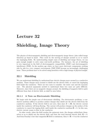
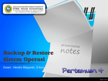
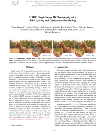
Living Image Software User’s Manual2 Getting StartedOverview of Imaging & Image Analysis . . . . . . . . . . . . . . . . . . . . . .For more details on sequence setup using the imaging wizard, see page 24.Initializing the IVIS Imaging System . . . . . . . . . . . . . . . . . . . . . . .Checking the System Temperature . . . . . . . . . . . . . . . . . . . . . . . . 5. 8. 11. 11This chapter provides a brief overview of images and image analysis. It also explainshow to start the Living Image software and initialize the IVIS imaging system.2.1 Overview of Imaging & Image AnalysisFor bioluminescence imaging, the imaging system acquires a photographic image and abioluminescence image. The Living Image software automatically coregisters theimages to generate an overlay image (Figure 2.1). For fluorescence imaging, the IVIS imaging system acquires a photographic and fluorescence image that are used togenerate an overlay image.Table 2.1 Images used to generate an overlay imageImage TypeDescriptionPhotographicA short exposure of the subject illuminated by the lights located at the topof the imaging chamber (Figure 2.2). The photographic image is displayedas a grayscale image.BioluminescenceA longer exposure of the subject taken in darkness to capture low levelbioluminescence emission. The bioluminescence image is displayed inpseudocolor that represents intensity (Figure 2.1). For more details onbioluminescence image data, see Appendix D, page 211.FluorescenceAn exposure of the subject illuminated by filtered light. The targetfluorophore emission is captured and focused on the CCD camera.Fluorescence image data can be displayed in units of counts or photons(absolute, calibrated), or in terms of efficiency (calibrated, normalized). Formore details on fluorescence image data, see Appendix F, page 223Figure 2.3shows an example workflow on an IVIS Imaging System.5
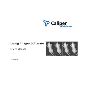
2. Getting StartedPhotographic imageBioluminescent imageOverlay imageFigure 2.1 Example bioluminescence overlay imageThe Living Image software automatically coregisters the photographic and bioluminescenceimages to generate the overlay image.Illumination LEDsCamera lens openingSample stageFigure 2.2 IVIS Imaging System 100 Series, interior view.6
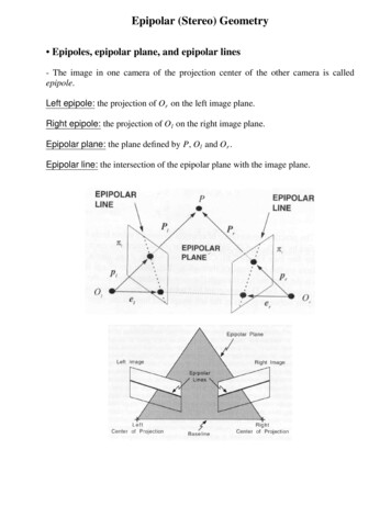
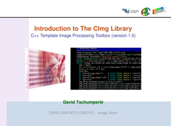
Living Image Software User’s Manual➊ Start the Living Image software. In the control panelthat appears, initialize the IVIS imaging system.➋ Confirm the default user preferences or specifynew preferences.➌ Specify acquisition settings for a single image, imagesequence, or kinetic sequence.➍ Acquire the image(s) or kinetic sequence.Toolpalette➏ View the image(s) or kinetic data. Analyze an image (Table 2.2), image sequence (Table 2.3), or kinetic dataFigure 2.3 Example imaging and analysis workflow7
2. Getting StartedTable 2.2 Image or kinetic sequence analysis toolsTool PaletteUse The Tools to.See PageImage Adjust Tune the photograph brightness, gamma (similar to contrast), or opacity Set the image display color scale min and max Select a color table for image display62Corrections/Filtering Subtract dark background from the image dataApply flat field correction to the image dataSpecify pixel binningSmooth the pixel signal66Image Information Display x,y coordinates and intensity data at a user-selected location on the imageDisplay a histogram of pixel intensities in an imagePlot the intensity (y-axis) at each pixel (x-axis) along a user-specified line in the imageMeasure distance in an image67ROI Measure counts or photons in a user-specified region of interest (ROI) and computemeasurement statistics (for example, average, min, max, standard deviation) Measure efficiency in the ROI and compute measurement statistics (for fluorescentimages only)81Table 2.3 Analyzing image sequencesAnalysisDescriptionWizardAvailableSee PagePlanar Spectral ImageAnalysisDetermines the average depth and total photon flux of a bioluminescentpoint source in a user-specified region of interest. Analyzes a sequence ofbioluminescent images acquired using different emission filters.Yes121Image MathA method for mathematically combining two images (add, multiply, orsubtract). Use image math to:No118 Remove autofluorescence from a fluorescent image Display multiple bioluminescent or fluorescent images on the samephotographic image so that you can view multiple reporters in one imageSpectral UnmixingRemoves tissue autofluorescence from a fluorescence image. Analyzes asequence of fluorescence images acquired using the fluorophoreexcitation filter and several different emission filters. Spectral unmixing canbe applied to images acquired using epi-illumination (excitation light abovethe stage) or transillumination (excitation light below the stage).Yes121Point Source FittingEstimates the optical properties of tissue, the location and power of a pointsource, or the fluorescent yield of fluorophores.Yes1433D FluorescenceImaging Tomography(FLIT )A 3-dimensional reconstruction of the image (tomographic analysis) thatestimates the location and intensity of a fluorescent light-emitting source.Analyzes a sequence of fluorescent images acquired on the IVIS Spectrumat different transillumination points (excitation light below the stage).Yes1523D DiffuseLuminescenceTomography (DLIT )A 3-dimensional reconstruction of the subject (tomographic analysis) thatestimates the depth and intensity of a bioluminescent light-emittingsource.Yes156NOTEFor more details on sequence setup using the imaging wizard, see page 24.8
Living Image Software User’s Manual2.2 Starting the Living Image SoftwareFor information on installing the software, see the Installation Guide included on theLiving Image CD ROM. By default, the software is installed at:PC: C:Programs:Xenogen:Living Image 3.2Macintosh: Applications:Xenogen:LivingImage 3.2NOTEAll components of the IVIS Imaging System should be left on at all times due to thelong cooling time required to reach operating (demand) temperature. It is alsoimportant to leave the system on to enable automatic overnight electronic backgroundmeasurements. Periodically rebooting the computer is permissible and does not affectthe camera operation.To start the software:1. PC Users: Click the Windows Start menu buttonand select All Programs Living Image. Alternatively, click the Living Image software desktop icon .Macintosh Users: Click the Living Image software desktop iconsoftware from the application folder.or run the- The main window appears.2. Select a user ID from the dropdown list or enter a new User ID(up to three letters), and click OK.- The control panel appears if theworkstation controls the IVISImaging System (see next page).9
2. Getting StartedMenu bar (for more details, see Appendix J, page 261)ToolbarThe acquisition control panel when the workstation controls the IVIS ImagingSystem (for more details, see Appendix A, page 191).NOTEThe Living Image software on the PC workstation that controls the IVIS ImagingSystem includes both the acquisition and analysis features. The Living Image softwareon other workstations includes only the analysis features. Macintosh users haveaccess to only the analysis features of the Living Image software.There are several ways to obtain help on the software features: To view a tooltip about a button function, put the mouse cursor over the button. To view a brief description about an item in the user interface, click the toolbarbutton, then click the item.Press F1 or select Help User Guide on the menu bar to display the Living Image 3.2Software User’s Manual (.pdf).10
Living Image Software User’s Manual2.3 Initializing the IVIS Imaging SystemThe imaging system must be initialized each time the Living Image software is started,or if the power has been cycled to the imaging chamber or the camera controller (acomponent of some IVIS systems). The initialization procedure moves every motordriven component in the system (for example, stage and lens) to a home position, resetsall electronics and controllers, and restores all software variables to the default settings.Initialization may be useful in error situations. For further details on instrumentoperation, see the hardware manual for your IVIS Imaging System.To initialize the imaging system:1. Start the Living Image software (double-click theicon on the desktop).2. In the control panel that appears, click Initialize.- You will hear the motors move.NOTEThe control panel is only available on the workstation that controls the imagingsystem. The items available in the IVIS System control panel depend on theparticular IVIS Imaging System and the imaging mode selected (luminescent orfluorescent, Image Setup or Sequence Setup mode).2.4 Checking the System TemperatureThe temperature box in the IVIS acquisition control panel indicates the temperaturestatus of the charge coupled device (CCD) camera (Figure 2.4). After you initialize thesystem, the temperature box turns green when the temperature is locked at the demandtemperature (-90 C or -105 C for IVIS Systems cooled by a Cryotiger unit),indicating the instrument is ready for operation and image acquisition.The demand temperature for the CCD camera is fixed. Electronic feedback controlmaintains the CCD camera temperature to within a few degrees of the demandtemperature.The default stage temperature on the IVIS imaging system is 37 C, but may be set toa temperature from 25-40 C.11
2. Getting StartedClick the temperature box toview the demand andmeasured temperatures ofthe CCD camera and stage.Temperature box color indicates:System not initialized.System is initialized, but CCD cameratemperature is out of range.System is initialized and CCD camera is at orwithin acceptable range of the demandtemperature and locked. The system is readyfor imaging.Figure 2.4 IVIS acquisition control panelNOTEThe items in the IVIS System control panel depend on the particular IVIS ImagingSystem and the imaging mode selected (luminescent or fluorescent, Image Setup orSequence Setup mode). For more details on the control panel, see Appendix A,page 191.The IVIS Imaging System is ready for image acquisition after the system is initializedand the operating (demand) temperature of the CCD camera is reached (locked). TheLiving Image software on the PC workstation that controls the IVIS Imaging Systemincludes both the acquisition and analysis features. The Living Image software on otherworkstations includes only the analysis features.2.5 About the IVIS Acquisition Control Panel & Auto Exposure FeatureThe control panel (Figure 2.5) provides the image acquisition functions. For details onthe imaging parameters in the control panel, see Appendix A, page 191.The auto exposure setting is useful in situations where the signal strength is unknownor varies widely, for example during a time course study. When you choose autoexposure (Figure 2.5), the system acquires an image at maximum sensitivity, thencalculates the required settings to achieve, as closely as possible, an image with a userspecified target max count. If the resulting image has too little signal or saturatedpixels, the software adjusts the parameters and takes another image.12
Living Image Software User’s ManualIn most cases, the default auto exposure settings provide a good bioluminescence orfluorescence image. However, you can modify the auto exposure preferences to meetyour needs. For more details, see page 199.To acquire an image using auto exposure,click thearrow and select Auto.Luminescenceimaging settingsFluorescenceimaging settingsPhotographicimaging settingsStructured lightimaging settingsFigure 2.5 IVIS acquisition control panel, auto exposure selectedNOTEThe options available in the IVIS acquisition control panel depend on the selectedimaging mode, the imaging system, and the filter wheel or lens option that areinstalled.13
2. Getting Started[This page intentionally blank.]14
Living Image Software User’s Manual3Acquire an Image or Image SequenceAcquire a Bioluminescence Image . . . . . . . . . . . .Acquire a Fluorescence Image With Epi-Illumination .Acquire a Fluorescence Image With TransilluminationAcquire an Image Sequence . . . . . . . . . . . . . . .Manually Setting the Focus . . . . . . . . . . . . . . . .Manually Saving Image Data . . . . . . . . . . . . . . .Exporting Image Data . . . . . . . . . . . . . . . . . . . 15. 18. 19. 22. 34. 34. 35The IVIS Imaging System is ready for image acquisition after the system is initializedand the CCD camera reaches operating (demand) temperature (locked).3.1 Acquire a Bioluminescence Image1. Start the Living Image software (double-click theicon on the desktop).2. Initialize the IVIS System and confirm or wait for the CCD temperature to lock. (Formore details, see page 11.)3. Put a check mark next to Luminescent.4. Confirm that Excitation Filter setting is Block and the Emission Filter setting isOpen.5. Select the Auto exposure time (click thearrow). Alternately, manually set theexposure, binning, and F/Stop. (For more details on the control panel settings, seepage 191.)6. Set the field of view: Make a selection from the Field of View drop-down list. Formore details on the field of view, see page 160.15
3. Acquire an Image or Image SequenceNOTETo view the subject(s)
The Living Image 3.2 software controls image acquisition on the IVIS Kinetic. The application also provides tools for optimizing image display and analyzing images or kinetic data. 1.1 What’s New In the Living Image 3.2 Software The Living Image 3.2 software enabl es kinetic data acquisition on the IVIS Kinetic and