Transcription
PRINCIPLES OF REMOTE SENSINGShefali AggarwalPhotogrammetry and Remote Sensing DivisionIndian Institute of Remote Sensing, Dehra DunAbstract : Remote sensing is a technique to observe the earth surface or theatmosphere from out of space using satellites (space borne) or from the air usingaircrafts (airborne). Remote sensing uses a part or several parts of theelectromagnetic spectrum. It records the electromagnetic energy reflected or emittedby the earth’s surface. The amount of radiation from an object (called radiance) isinfluenced by both the properties of the object and the radiation hitting the object(irradiance). The human eyes register the solar light reflected by these objects andour brains interpret the colours, the grey tones and intensity variations. In remotesensing various kinds of tools and devices are used to make electromagnetic radiationoutside this range from 400 to 700 nm visible to the human eye, especially thenear infrared, middle-infrared, thermal-infrared and microwaves.Remote sensing imagery has many applications in mapping land-use and cover,agriculture, soils mapping, forestry, city planning, archaeological investigations,military observation, and geomorphological surveying, land cover changes,deforestation, vegetation dynamics, water quality dynamics, urban growth, etc. Thispaper starts with a brief historic overview of remote sensing and then explains thevarious stages and the basic principles of remotely sensed data collection mechanism.INTRODUCTIONRemote sensing (RS), also called earth observation, refers to obtaininginformation about objects or areas at the Earth’s surface without beingin direct contact with the object or area. Humans accomplish this task withaid of eyes or by the sense of smell or hearing; so, remote sensing is day-today business for people. Reading the newspaper, watching cars driving in frontof you are all remote sensing activities. Most sensing devices record informationabout an object by measuring an object’s transmission of electromagnetic energyfrom reflecting and radiating surfaces.Satellite Remote Sensing and GIS Applications in Agricultural Meteorologypp. 23-38
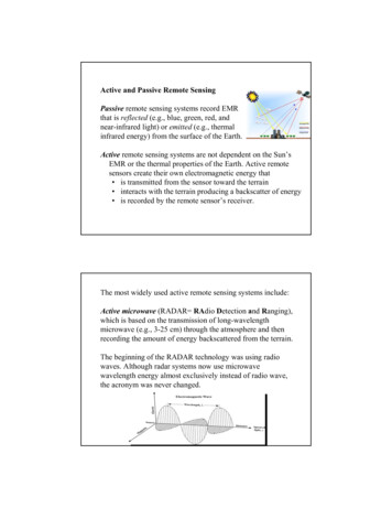
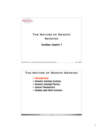
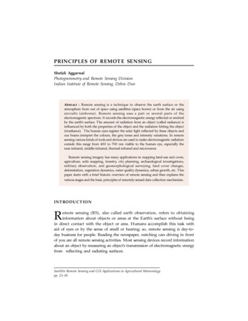
Principles of Remote Sensing24Remote sensing techniques allow taking images of the earth surface invarious wavelength region of the electromagnetic spectrum (EMS). One of themajor characteristics of a remotely sensed image is the wavelength region itrepresents in the EMS. Some of the images represent reflected solar radiationin the visible and the near infrared regions of the electromagnetic spectrum,others are the measurements of the energy emitted by the earth surface itselfi.e. in the thermal infrared wavelength region. The energy measured in themicrowave region is the measure of relative return from the earth’s surface,where the energy is transmitted from the vehicle itself. This is known as activeremote sensing, since the energy source is provided by the remote sensingplatform. Whereas the systems where the remote sensing measurementsdepend upon the external energy source, such as sun are referred to as passiveremote sensing systems.PRINCIPLES OF REMOTE SENSINGDetection and discrimination of objects or surface features means detectingand recording of radiant energy reflected or emitted by objects or surfacematerial (Fig. 1). Different objects return different amount of energy in differentbands of the electromagnetic spectrum, incident upon it. This depends onthe property of material (structural, chemical, and physical), surface roughness,angle of incidence, intensity, and wavelength of radiant energy.The Remote Sensing is basically a multi-disciplinary science which includesa combination of various disciplines such as optics, spectroscopy, photography,computer, electronics and telecommunication, satellite launching etc. All thesetechnologies are integrated to act as one complete system in itself, known asRemote Sensing System. There are a number of stages in a Remote Sensingprocess, and each of them is important for successful operation.Stages in Remote Sensing Emission of electromagnetic radiation, or EMR (sun/self- emission) Transmission of energy from the source to the surface of the earth, as wellas absorption and scattering Interaction of EMR with the earth’s surface: reflection and emission Transmission of energy from the surface to the remote sensor Sensor data output
Shefali Aggarwal25SunSatelliteReflectedSolar RadiationPre-Process and ArchiveDistribute for AnalysisAtmosphereDown LinkForestWaterGrassBare SoilPavedRoadBuilt-up AreaFigure 1: Remote Sensing process Data transmission, processing and analysisWhat we seeAt temperature above absolute zero, all objects radiate electromagneticenergy by virtue of their atomic and molecular oscillations. The total amountof emitted radiation increases with the body’s absolute temperature and peaksat progressively shorter wavelengths. The sun, being a major source of energy,radiation and illumination, allows capturing reflected light with conventional(and some not-so-conventional) cameras and films.The basic strategy for sensing electromagnetic radiation is clear. Everythingin nature has its own unique distribution of reflected, emitted and absorbedradiation. These spectral characteristics, if ingeniously exploited, can be usedto distinguish one thing from another or to obtain information about shape,size and other physical and chemical properties.Modern Remote Sensing Technology versus Conventional Aerial PhotographyThe use of different and extended portions of the electromagneticspectrum, development in sensor technology, different platforms for remotesensing (spacecraft, in addition to aircraft), emphasize on the use of spectralinformation as compared to spatial information, advancement in imageprocessing and enhancement techniques, and automated image analysis inaddition to manual interpretation are points for comparison of conventionalaerial photography with modern remote sensing system.
26Principles of Remote SensingDuring early half of twentieth century, aerial photos were used in militarysurveys and topographical mapping. Main advantage of aerial photos has beenthe high spatial resolution with fine details and therefore they are still usedfor mapping at large scale such as in route surveys, town planning,construction project surveying, cadastral mapping etc. Modern remote sensingsystem provide satellite images suitable for medium scale mapping used innatural resources surveys and monitoring such as forestry, geology, watershedmanagement etc. However the future generation satellites are going to providemuch high-resolution images for more versatile applications.HISTORIC OVERVIEWIn 1859 Gaspard Tournachon took an oblique photograph of a small villagenear Paris from a balloon. With this picture the era of earth observation andremote sensing had started. His example was soon followed by other peopleall over the world. During the Civil War in the United States aerialphotography from balloons played an important role to reveal the defencepositions in Virginia (Colwell, 1983). Likewise other scientific and technicaldevelopments this Civil War time in the United States speeded up thedevelopment of photography, lenses and applied airborne use of thistechnology. Table 1 shows a few important dates in the development of remotesensing.The next period of fast development took place in Europe and not in theUnited States. It was during World War I that aero planes were used on alarge scale for photoreconnaissance. Aircraft proved to be more reliable andmore stable platforms for earth observation than balloons. In the periodbetween World War I and World War II a start was made with the civilianuse of aerial photos. Application fields of airborne photos included at thattime geology, forestry, agriculture and cartography. These developments leadto much improved cameras, films and interpretation equipment. The mostimportant developments of aerial photography and photo interpretation tookplace during World War II. During this time span the development of otherimaging systems such as near-infrared photography; thermal sensing and radartook place. Near-infrared photography and thermal-infrared proved veryvaluable to separate real vegetation from camouflage. The first successfulairborne imaging radar was not used for civilian purposes but proved valuablefor nighttime bombing. As such the system was called by the military ‘planposition indicator’ and was developed in Great Britain in 1941.
Shefali Aggarwal27After the wars in the 1950s remote sensing systems continued to evolvefrom the systems developed for the war effort. Colour infrared (CIR)photography was found to be of great use for the plant sciences. In 1956Colwell conducted experiments on the use of CIR for the classification andrecognition of vegetation types and the detection of diseased and damaged orstressed vegetation. It was also in the 1950s that significant progress in radartechnology was achieved.Table1: Milestones in the History of Remote Sensing1800Discovery of Infrared by Sir W. Herschel1839Beginning of Practice of Photography1847Infrared Spectrum Shown by J.B.L. Foucault1859Photography from Balloons1873Theory of Electromagnetic Spectrum by J.C. Maxwell1909Photography from Airplanes1916World War I: Aerial Reconnaissance1935Development of Radar in Germany1940WW II: Applications of Non-Visible Part of EMS1950Military Research and Development1959First Space Photograph of the Earth (Explorer-6)1960First TIROS Meteorological Satellite Launched1970Skylab Remote Sensing Observations from Space1972Launch Landsat-1 (ERTS-1) : MSS Sensor1972Rapid Advances in Digital Image Processing1982Launch of Landsat -4 : New Generation of Landsat Sensors: TM1986French Commercial Earth Observation Satellite SPOT1986Development Hyperspectral Sensors1990Development High Resolution Space borne SystemsFirst Commercial Developments in Remote Sensing1998Towards Cheap One-Goal Satellite Missions1999Launch EOS : NASA Earth Observing Mission1999Launch of IKONOS, very high spatial resolution sensor system
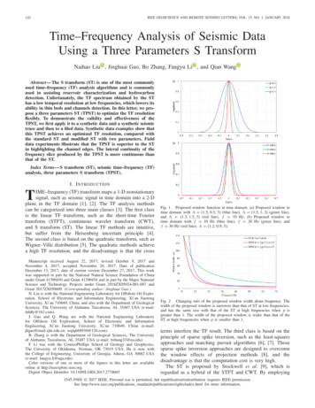
Principles of Remote Sensing28ELECTROMAGNETIC RADIATION AND THE ELECTROMAGNETICSPECTRUMEMR is a dynamic form of energy that propagates as wave motion at a velocityof c 3 x 1010 cm/sec. The parameters that characterize a wave motion arewavelength (λ), frequency (ν) and velocity (c) (Fig. 2). The relationshipbetween the above isc νλ.Figure 2: Electromagnetic wave. It has two components, Electric field E and Magneticfield M, both perpendicular to the direction of propagationElectromagnetic energy radiates in accordance with the basic wave theory.This theory describes the EM energy as travelling in a harmonic sinusoidalfashion at the velocity of light. Although many characteristics of EM energyare easily described by wave theory, another theory known as particle theoryoffers insight into how electromagnetic energy interacts with matter. It suggeststhat EMR is composed of many discrete units called photons/quanta. Theenergy of photon isQ hc / λ h νWhereQ is the energy of quantum,h Planck’s constant
Shefali Aggarwal29Table 2: Principal Divisions of the Electromagnetic SpectrumWavelengthDescriptionGamma raysGamma raysX-raysX-raysUltraviolet (UV) region0.30 µm - 0.38 µm(1µm 10-6m)This region is beyond the violet portion of the visiblewavelength, and hence its name. Some earth’s surfacematerial primarily rocks and minerals emit visible UVradiation. However UV radiation is largely scatteredby earth’s atmosphere and hence not used in field ofremote sensing.Visible Spectrum0.4 µm - 0.7 µmViolet 0.4 µm -0.446 µmBlue 0.446 µm -0.5 µmGreen 0.5 µm - 0.578 µmYellow 0.578 µm - 0.592 µmOrange 0.592 µm - 0.62 µmRed 0.62 µm -0.7 µmThis is the light, which our eyes can detect. This isthe only portion of the spectrum that can beassociated with the concept of color. Blue Green andRed are the three primary colors of the visiblespectrum. They are defined as such because no singleprimary color can be created from the other two, butall other colors can be formed by combining thethree in various proportions. The color of an objectis defined by the color of the light it reflects.Infrared (IR) Spectrum0.7 µm – 100 µmWavelengths longer than the red portion of thevisible spectrum are designated as the infraredspectrum. British Astronomer William Herscheldiscovered this in 1800. The infrared region can bedivided into two categories based on their radiationproperties.Reflected IR (.7 µm - 3.0 µm) is used for remotesensing. Thermal IR (3 µm - 35 µm) is the radiationemitted from earth’s surface in the form of heat andused for remote sensing.Microwave Region1 mm - 1 mThis is the longest wavelength used in remote sensing.The shortest wavelengths in this range haveproperties similar to thermal infrared region. Themain advantage of this spectrum is its ability topenetrate through clouds.Radio Waves( 1 m)This is the longest portion of the spectrum mostlyused for commercial broadcast and meteorology.
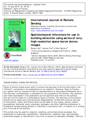
Principles of Remote Sensing30Types of Remote SensingRemote sensing can be either passive or active. ACTIVE systems have theirown source of energy (such as RADAR) whereas the PASSIVE systems dependupon external source of illumination (such as SUN) or self-emission for remotesensing.INTERACTION OF EMR WITH THE EARTH’S SURFACERadiation from the sun, when incident upon the earth’s surface, is eitherreflected by the surface, transmitted into the surface or absorbed and emittedby the surface (Fig. 3). The EMR, on interaction, experiences a number ofchanges in magnitude, direction, wavelength, polarization and phase. Thesechanges are detected by the remote sensor and enable the interpreter to obtainuseful information about the object of interest. The remotely sensed datacontain both spatial information (size, shape and orientation) and spectralinformation (tone, colour and spectral signature).EI (λ) Incident energyEI (λ) ER(λ) EA (λ) ET (λ)ER (λ) Reflected energyEA(λ) Absorbed energyET(λ) Transmitted energyFigure 3: Interaction of Energy with the earth’s surface. ( source: Liliesand & Kiefer, 1993)From the viewpoint of interaction mechanisms, with the object-visible andinfrared wavelengths from 0.3 µm to 16 µm can be divided into three regions.The spectral band from 0.3 µm to 3 µm is known as the reflective region. Inthis band, the radiation sensed by the sensor is that due to the sun, reflected
Shefali Aggarwal31by the earth’s surface. The band corresponding to the atmospheric windowbetween 8 µm and 14 µm is known as the thermal infrared band. The energyavailable in this band for remote sensing is due to thermal emission from theearth’s surface. Both reflection and self-emission are important in theintermediate band from 3 µm to 5.5 µm.In the microwave region of the spectrum, the sensor is radar, which is anactive sensor, as it provides its own source of EMR. The EMR produced bythe radar is transmitted to the earth’s surface and the EMR reflected (backscattered) from the surface is recorded and analyzed. The microwave regioncan also be monitored with passive sensors, called microwave radiometers, whichrecord the radiation emitted by the terrain in the microwave region.ReflectionOf all the interactions in the reflective region, surface reflections are themost useful and revealing in remote sensing applications. Reflection occurswhen a ray of light is redirected as it strikes a non-transparent surface. Thereflection intensity depends on the surface refractive index, absorptioncoefficient and the angles of incidence and reflection (Fig. 4).Figure 4. Different types of scattering surfaces (a) Perfect specular reflector (b) Near perfectspecular reflector (c) Lambertain (d) Quasi-Lambertian (e) Complex.TransmissionTransmission of radiation occurs when radiation passes through asubstance without significant attenuation. For a given thickness, or depth ofa substance, the ability of a medium to transmit energy is measured astransmittance (τ).
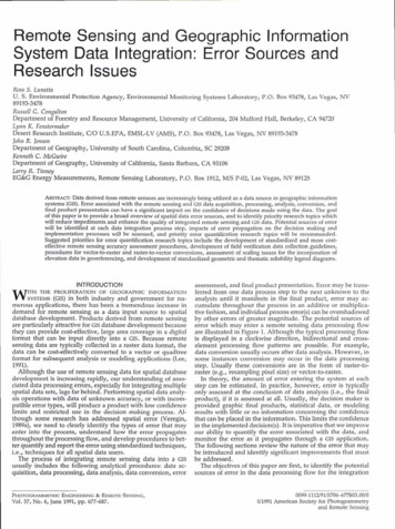
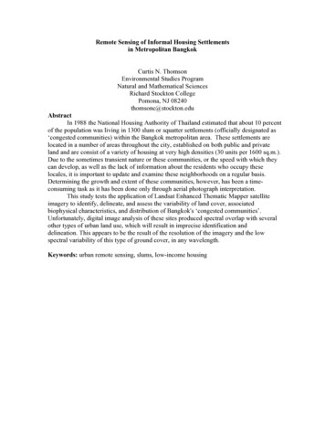
Principles of Remote Sensing32Transmitted radiationτ ———————————Incident radiationSpectral SignatureSpectral reflectance, [ρ(λ)], is the ratio of reflected energy to incidentenergy as a function of wavelength. Various materials of the earth’s surface havedifferent spectral reflectance characteristics. Spectral reflectance is responsiblefor the color or tone in a photographic image of an object. Trees appear greenbecause they reflect more of the green wavelength. The values of the spectralreflectance of objects averaged over different, well-defined wavelength intervalscomprise the spectral signature of the objects or features by which they canbe distinguished. To obtain the necessary ground truth for the interpretationof multispectral imagery, the spectral characteristics of various natural objectshave been extensively measured and recorded.The spectral reflectance is dependent on wavelength, it has different valuesat different wavelengths for a given terrain feature. The reflectancecharacteristics of the earth’s surface features are expressed by spectral reflectance,which is given by:ρ(λ) [ER(λ) / EI(λ)] x 100Where,ρ(λ) Spectral reflectance (reflectivity) at a particular wavelength.E R(λ) Energy of wavelength reflected from objectEI(λ) Energy of wavelength incident upon the objectThe plot between ρ(λ) and λ is called a spectral reflectance curve. Thisvaries with the variation in the chemical composition and physical conditionsof the feature, which results in a range of values. The spectral response patternsare averaged to get a generalized form, which is called generalized spectralresponse pattern for the object concerned. Spectral signature is a term usedfor unique spectral response pattern, which is characteristic of a terrain feature.Figure 5 shows a typical reflectance curves for three basic types of earth surfacefeatures, healthy vegetation, dry bare soil (grey-brown and loamy) and clearlake water.
Shefali AggarwalReflectance (%)6033VegetationDry soil(5% water)40Wet soil(20% water)20Clear lake waterTurbid river water00.40.60.81 231 2 341.0 1.21.4 1.61.8 2.0Wavelength (micrometers)SPOT XS Multispectral Bands5Landsat TM Bands2.22.47Middle InfraredReflected InfraredFigure 5. Typical Spectral Reflectance curves for vegetation, soil and waterReflectance Characteristics of Earth’s Cover typesThe spectral characteristics of the three main earth surface features arediscussed below :Vegetation: The spectral characteristics of vegetation vary with wavelength.Plant pigment in leaves called chlorophyll strongly absorbs radiation in thered and blue wavelengths but reflects green wavelength. The internal structureof healthy leaves acts as diffuse reflector of near infrared wavelengths.Measuring and monitoring the near infrared reflectance is one way thatscientists determine how healthy particular vegetation may be.Water: Majority of the radiation incident upon water is not reflected but iseither absorbed or transmitted. Longer visible wavelengths and near infraredradiation is absorbed more by water than by the visible wavelengths. Thuswater looks blue or blue green due to stronger reflectance at these shorterwavelengths and darker if viewed at red or near infrared wavelengths. Thefactors that affect the variability in reflectance of a water body are depth ofwater, materials within water and surface roughness of water.Soil: The majority of radiation incident on a soil surface is either reflected orabsorbed and little is transmitted. The characteristics of soil that determine
Principles of Remote Sensing34its reflectance properties are its moisture content, organic matter content,texture, structure and iron oxide content. The soil curve shows less peak andvalley variations. The presence of moisture in soil decreases its reflectance.By measuring the energy that is reflected by targets on earth’s surface overa variety of different wavelengths, we can build up a spectral signature forthat object. And by comparing the response pattern of different features wemay be able to distinguish between them, which we may not be able to do ifwe only compare them at one wavelength. For example, Water and Vegetationreflect somewhat similarly in the visible wavelength but not in the infrared.INTERACTIONS WITH THE ATMOSPHEREThe sun is the source of radiation, and electromagnetic radiation (EMR)from the sun that is reflected by the earth and detected by the satellite oraircraft-borne sensor must pass through the atmosphere twice, once on itsjourney from the sun to the earth and second after being reflected by thesurface of the earth back to the sensor. Interactions of the direct solar radiationand reflected radiation from the target with the atmospheric constituentsinterfere with the process of remote sensing and are called as “AtmosphericEffects”.The interaction of EMR with the atmosphere is important to remotesensing for two main reasons. First, information carried by EMR reflected/emitted by the earth’s surface is modified while traversing through theatmosphere. Second, the interaction of EMR with the atmosphere can be usedto obtain useful information about the atmosphere itself.The atmospheric constituents scatter and absorb the radiation modulatingthe radiation reflected from the target by attenuating it, changing its spatialdistribution and introducing into field of view radiation from sunlightscattered in the atmosphere and some of the energy reflected from nearbyground area. Both scattering and absorption vary in their effect from one partof the spectrum to the other.The solar energy is subjected to modification by several physical processesas it passes the atmosphere, viz.1) Scattering;2) Absorption, and 3) Refraction
Shefali Aggarwal35Atmospheric ScatteringScattering is the redirection of EMR by particles suspended in theatmosphere or by large molecules of atmospheric gases. Scattering not onlyreduces the image contrast but also changes the spectral signature of groundobjects as seen by the sensor. The amount of scattering depends upon thesize of the particles, their abundance, the wavelength of radiation, depth ofthe atmosphere through which the energy is traveling and the concentrationof the particles. The concentration of particulate matter varies both in timeand over season. Thus the effects of scattering will be uneven spatially andwill vary from time to time.Theoretically scattering can be divided into three categories dependingupon the wavelength of radiation being scattered and the size of the particlescausing the scattering. The three different types of scattering from particlesof different sizes are summarized enceparticle sizeKindsof particlesλ -4 1 µmAir moleculesλo to λ-4λo0.1 to 10 µmSmoke, hazeSelectivezRayleighzMiezNon-selective 10 µmDust, fog, cloudsRayleigh ScatteringRayleigh scattering predominates where electromagnetic radiation interactswith particles that are smaller than the wavelength of the incoming light. Theeffect of the Rayleigh scattering is inversely proportional to the fourth powerof the wavelength. Shorter wavelengths are scattered more than longerwavelengths. In the absence of these particles and scattering the sky wouldappear black. In the context of remote sensing, the Rayleigh scattering is themost important type of scattering. It causes a distortion of spectralcharacteristics of the reflected light when compared to measurements takenon the ground.
36Principles of Remote SensingMie ScatteringMie scattering occurs when the wavelength of the incoming radiation issimilar in size to the atmospheric particles. These are caused by aerosols: amixture of gases, water vapor and dust. It is generally restricted to the loweratmosphere where the larger particles are abundant and dominates underovercast cloud conditions. It influences the entire spectral region from ultraviolet to near infrared regions.Non-selective ScatteringThis type of scattering occurs when the particle size is much larger thanthe wavelength of the incoming radiation. Particles responsible for this effectare water droplets and larger dust particles. The scattering is independent ofthe wavelength, all the wavelength are scattered equally. The most commonexample of non-selective scattering is the appearance of clouds as white. Ascloud consist of water droplet particles and the wavelengths are scattered inequal amount, the cloud appears as white.Occurrence of this scattering mechanism gives a clue to the existence oflarge particulate matter in the atmosphere above the scene of interest whichitself is a useful data. Using minus blue filters can eliminate the effects of theRayleigh component of scattering. However, the effect of heavy haze i.e. whenall the wavelengths are scattered uniformly, cannot be eliminated using hazefilters. The effects of haze are less pronounced in the thermal infrared region.Microwave radiation is completely immune to haze and can even penetrateclouds.Atmospheric AbsorptionThe gas molecules present in the atmosphere strongly absorb the EMRpassing through the atmosphere in certain spectral bands. Mainly three gasesare responsible for most of absorption of solar radiation, viz. ozone, carbondioxide and water vapour. Ozone absorbs the high energy, short wavelengthportions of the ultraviolet spectrum (λ 0.24 µm) thereby preventing thetransmission of this radiation to the lower atmosphere. Carbon dioxide isimportant in remote sensing as it effectively absorbs the radiation in mid andfar infrared regions of the spectrum. It strongly absorbs in the region fromabout 13-17.5 µm, whereas two most important regions of water vapourabsorption are in bands 5.5 - 7.0 µm and above 27 µm. Absorption relatively
Shefali Aggarwal37reduces the amount of light that reaches our eye making the scene lookrelatively duller.Atmospheric WindowsThe general atmospheric transmittance across the whole spectrum ofwavelengths is shown in Figure 6. The atmosphere selectively transmits energyof certain wavelengths. The spectral bands for which the atmosphere isrelatively transparent are known as atmospheric windows. Atmosphericwindows are present in the visible part (.4 µm - .76 µm) and the infraredregions of the EM spectrum. In the visible part transmission is mainly effectedby ozone absorption and by molecular scattering. The atmosphere is transparentagain beyond about λ 1mm, the region used for microwave remote sensing.0.3 0.61.05.01050100 200 mmicrowavesIIRTIRVIIRVIIRIIIRVIS0.0blocking effect of atmosphereUVatmospherictransmittance1.01mm 1cm 1m 10mWavelengthFigure 6 : Atmospheric windowsRefractionThe phenomenon of refraction, that is bending of light at the contactbetween two media, also occurs in the atmosphere as the light passes throughthe atmospheric layers of varied clarity, humidity and temperature. Thesevariations influence the density of atmospheric layers, which in turn, causesthe bending of light rays as they pass from one layer to another. The mostcommon phenomena are the mirage like apparitions sometimes visible in thedistance on hot summer days.CONCLUSIONSRemote sensing technology has developed from balloon photography toaerial photography to multi-spectral satellite imaging. Radiation interactioncharacteristics of earth and atmosphere in different regions of electromagnetic
38Principles of Remote Sensingspectrum are very useful for identifying and characterizing earth andatmospheric features.REFERENCESCampbell, J.B. 1996. Introduction to Remote Sensing. Taylor & Francis, London.Colwell, R.N. (Ed.) 1983. Manual of Remote Sensing. Second Edition. Vol I: Theory,Instruments and Techniques. American Society of Photogrammetry and Remote SensingASPRS, Falls Church.Curran, P.J. 1985. Principles of Remote Sensing. Longman Group Limited, London.Elachi, C. 1987. Introduction to the Physics and Techniques of Remote Sensing. Wiley Seriesin Remote Sensing, New als/fundam/chapter1/chapter1 1 e.htmlJoseph, G. 1996. Imaging Sensors. Remote Sensing Reviews, 13: 257-342.Lillesand, T.M. and Kiefer, R.1993. Remote Sensing and Image Interpretation. Third EditionJohn Villey, New York.Manual of Remote Sensing. IIIrd Edition. American Society of Photogrammtery and RemoteSensing.Sabins, F.F. 1997. Remote Sensing and Principles and Image Interpretation. WH Freeman,New York.
The human eyes register the solar light reflected by these objects and our brains interpret the colours, the grey tones and intensity variations. . Satellite Remote Sensing and GIS Applications in Agricultural Meteorology pp. 23-38. . The Remote Sensing is basically a multi-disciplinary science which includes a combination of various .