Transcription
Understanding and Mitigating the Impact ofRF Interference on 802.11 NetworksRamakrishna Gummadi USC†David Wetherall†‡Intel Research‡ UniversityAbstractWe study the impact on 802.11 networks of RF interference fromdevices such as Zigbee and cordless phones that increasingly crowdthe 2.4GHz ISM band, and from devices such as wireless camera jammers and non-compliant 802.11 devices that seek to disrupt802.11 operation. Our experiments show that commodity 802.11equipment is surprisingly vulnerable to certain patterns of weak ornarrow-band interference. This enables us to disrupt a link with aninterfering signal whose power is 1000 times weaker than the victim’s 802.11 signals, or to shut down a multiple AP, multiple channel managed network at a location with a single radio interferer.We identify several factors that lead to these vulnerabilities, ranging from MAC layer driver implementation strategies to PHY layerradio frequency implementation strategies. Our results further showthat these factors are not overcome by simply changing 802.11 operational parameters (such as CCA threshold, rate and packet size)with the exception of frequency shifts. This leads us to explore rapidchannel hopping as a strategy to withstand RF interference. We prototype a channel hopping design using PRISM NICs, and find thatit can sustain throughput at levels of RF interference well abovethat needed to disrupt unmodified links, and at a reasonable cost interms of switching overheads.Categories and Subject Descriptors:C.4 [Performance of Systems]: Measurement Techniques; C.2.1[Computer-Communication Networks]: Network Architectureand DesignGeneral Terms: Experimentation, Measurement, Performance,SecurityKeywords: 802.11, RF Interference, SINR, Jamming, Channelhopping1Ben Greenstein†IntroductionOur reliance on wireless communications such as 802.11 is increasing. Wireless technology is now used as an alternative to wired networks in enterprises [12], to enable mobility in safety critical settings like hospitals, and to provide city-wide Internet access [10].In each of these cases, high network availability is desirable. Unfortunately, by their nature, wireless transmissions are vulnerable to RF (Radio Frequency) interference from various sources.This weakness is a growing problem for technologies that operate in unlicensed frequency bands, as these bands are becomingmore crowded over time [3]. 802.11b/g networks which use the2.4GHz band now compete with a wide range of wireless devicesthat includes 2.4GHz cordless phones, Bluetooth headsets, Zigbee Work done while the author was at Intel Research Seattle. Thismaterial is based in part upon work supported by the National ScienceFoundation under Grant No. 0520192.Permission to make digital or hard copies of all or part of this work forpersonal or classroom use is granted without fee provided that copies arenot made or distributed for profit or commercial advantage and that copiesbear this notice and the full citation on the first page. To copy otherwise, torepublish, to post on servers or to redistribute to lists, requires prior specificpermission and/or a fee.SIGCOMM’07, August 27–31, 2007, Kyoto, Japan.Copyright 2007 ACM 978-1-59593-713-1/07/0008 . . . 5.00.of WashingtonSrinivasan Seshan§§ CMU(IEEE 802.15.4) embedded devices, 2.4GHz RFID tags, and proprietary devices such as the ANT radios [4], Chipcon 2.4GHz RFtransceivers [9] and Cypress “WirelessUSB” peripherals [31].Although the use of unlicensed bands does not require coordination between the deployers of devices, not all forms of device behavior is permitted. To promote coexistence, devices must meet anumber of FCC regulations that limit transmission power and forcetransmitters to spread their signals. Wireless technologies oftenhave mechanisms in their MAC and PHY layers that go beyond thebasic FCC/ITU rules to improve coexistence. For example, 802.11uses carrier sense to detect and defer to 802.11 and other transmitters. Similarly, Bluetooth adaptively hops frequencies to decreaseinterference on 802.11 [7]. However, unlicensed band coexistenceand additional precautions have not prevented a range of interference problems across the n2 combinations of wireless technologiesthat may interact. In fact, there are reports of interference betweentechnologies that are specifically designed to coexist (e.g., 802.11and Bluetooth [29]). Moreover, mechanisms for politely accommodating other transmitters, such as carrier sense in 802.11, can maketechnologies more susceptible to interference from other devices.Our goal is to explore the impact of interference on 802.11 linksand to develop techniques that make 802.11 more resistant to interference. To develop an understanding of the key factors, we subjectan 802.11 network consisting of a single AP and a single nearbyclient to commonly available RF sources and measure the effecton client/AP performance. Since 802.11 already uses many mechanisms to mitigate noise and interference, it is natural to ask whether802.11 links are already as robust to interference as can reasonably be expected. These mechanisms include: 1) a MAC protocolthat avoids collisions; 2) lower transmission rates that accommodate lower signal-to-interference-plus-noise (SINR) ratios; 3) signal spreading that tolerates narrow-band fading and interference;and 4) PHY layer coding for error correction. However, we areaware of little published work that we can use to answer this question because past studies consider RF sources that follow 802.11protocols in either the same or adjacent channels [17, 19, 21, 22].We consider both selfish interferers such as Zigbee nodes and cordless phones that co-exist in the unlicensed band and run their ownprotocol for their own benefit, and malicious interferers such aswireless jammers [30] that actively seek to deny service to othernodes to achieve their own ends.Our experimental results confirm anecdotal evidence that a rangeof selfish and malicious interferers (802.11 waveforms, Zigbee, awireless camera jammer, a cordless phone) cause 802.11 performance to degrade much more significantly than expected from simple SINR considerations. Surprisingly, we find that even highly attenuated signals from malicious devices can cause severe losses atthe receiver. We identify a number of properties of a typical NIC(Network Interface Card) implementation of the 802.11 PHY andMAC layers that is to blame for this poor performance. This leadsus to extend the classic SINR model of successful packet transmissions to account for these effects.This extended model helps us to understand the performancedegradations that we observe, as well as predict the utility of otherstrategies; we check these predictions experimentally to build confi-
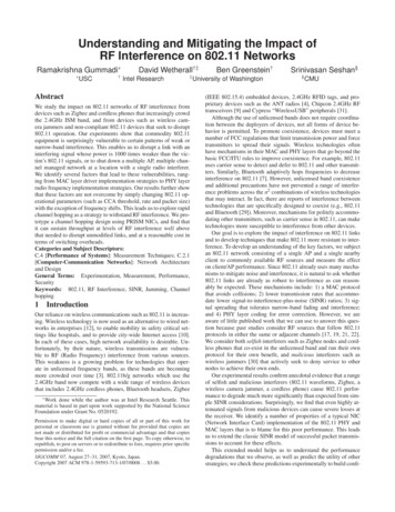
dence in our model. In particular, the model shows why some likelyinterference mitigation techniques are of little help because of receiver path limitations. For example, high sender transmit power,large channel bandwidth compared to a narrow-band interferer,high receiver selectivity, and multi-antenna and spatial diversitytechniques used in the new 802.11n do not gracefully tolerate interference. It also highlights that existing 802.11 implementations areable to tolerate interference when it is modestly off the center of thefrequency channel that they are using, e.g., when it is in an adjacentchannel even though this adjacent channel is not orthogonal. Thisis a surprising and useful result because there are only three nonoverlapping (i.e., orthogonal) channels in the 2.4GHz band, whilethere are eleven overlapping channels.Motivated by these observations, we design a channel hoppingscheme and evaluate its ability to withstand interference. Our goal isthat performance degrades gracefully and slowly with increasinglylarge levels of interference. We use commodity (PRISM) chipsetsto prototype our design. In it, clients and the AP switch to a pseudorandom channel rapidly (250µ s channel switching latency), andoccupy it for a short period (10ms dwell period) before switchingagain. This makes it difficult for both selfish and malicious devicesto jam a link for an extended period. This is because they mustfirst find the channel that the link is using at a given time (or jamall channels, which is considerably more expensive). We find theoverhead of channel hopping to be acceptably small, and the improvement in performance under interference to be large. Withouthopping, the effect of a single interferer is catastrophic. With hopping, even three interferers jamming all three orthogonal channelscannot degrade performance to low levels.In this paper, we make three contributions. First, we quantifythe extent and magnitude of 802.11’s vulnerability to interference,and relate the causes of such vulnerability to design limitations incommodity NICs. Second, we extend the SINR model to capturethese limitations, and quantify how our extended version can beused to predict the high interference degradation with even weakand narrow-band interferers seen in practice. We also use the modelto show that changing 802.11 operational parameters would be ineffective at mitigating this degradation, while channel hopping canbe helpful. Third, we implement and evaluate a rapid channel hopping scheme that can withstand even multiple strong interferers in arealistic setting, at a reasonable cost in terms of channel switchingoverheads.The rest of the paper is organized as follows. We briefly review802.11 in the next section, then describe our experimental setup inSection 3. We describe our experiments to gauge the effects of interference in Section 4, and extend the SINR model to capture theseeffects in Section 5. Our channel hopping solution is developed inSection 6. We then consider related work in Section 7 and concludein Section 8.2802.11 BackgroundWe briefly review 802.11b/g as it is relevant to our work. 802.11nodes follow a contention-based CSMA/CA MAC defined by theIEEE standard. Normally, the 802.11 radio is in receive mode.When a node has a packet to send, it enters the transmit mode andwaits for a certain time period to make sure the medium is free(CSMA). It uses a Clear Channel Assessment (CCA) module thatmay be configured in several modes to make this determination. InMode 1, the transmitter declares the medium busy if it detects anysignal energy above the Energy Detect (ED) threshold. In mode 2,it declares a busy medium if it detects any valid 802.11-modulatedsignal. In mode 3, a busy medium is declared only when a valid802.11-modulated signal that exceeds the ED threshold is detected.Normally, mode 2 is used.SFD SIGNAL SERVICE LENGTH CRCSYNCMAC(128 bits) (16 bits) (8 bits) (8 bits) (16 bits) (16 bits)Energy Detection, PHY HeaderTiming RecoveryDetectionPLCP Preamble(144 bits)PHY DurationEstimationPLCP Header(48 bits)PHY PSDU(2304 bytes max)PPDU(PLCP Protocol Data Unit)Figure 1—802.11 PHY encapsulation and its usage at the receiver.If the CCA module declares the medium to be free, the packet issent. If it is busy, the transmitter defers the transmission for a random number of 20µ s slots selected between 1 and the ContentionWindow (CW), and repeats the CCA procedure. The CW is doubled with successive deferrals, up to a maximum of 127 slots; thepacket is sent if this maximum is reached regardless of whether themedium is busy. The CW is reset to a minimum value after a transmission.Receivers send an ACK packet within a fixed time limit to acknowledge the receipt of a non-broadcast data packet that passesthe CRC check for data integrity. If the transmitter does not receivean ACK, it considers the packet (or its ACK) lost. It then retransmitsthe packet by re-inserting it at the front of the transmission queueand treating it as a new packet. Retransmission can be repeated upto seven times, after which the packet is dropped. Optionally, nodescan precede data packets with a RTS/CTS exchange to reduce thelikelihood of interference by hidden terminals, but most implementations choose not to do so in practice because the costs outweighthe benefits.The 802.11 MAC also defines management packets, the mostrelevant here being beacons and probes. An AP periodically ( 100ms) broadcasts beacons to assist clients with association, roaming, synchronization, power-saving and other tasks. Beacons carryan 8-octet timestamp field so that the client’s NIC can synchronizeits clock with the AP to meet the timing constraints of the 802.11MAC. Probe packets are sent by a client to discover APs.Reception at a node can be explained in terms of the PLCP(Physical Layer Convergence Protocol) headers that encapsulatepackets (shown in Figure 1). Processing steps are shown as ovals.To begin, a preamble of a SYNC bit-pattern triggers the energy detection circuitry that alerts the receiver to an incoming transmission. This bit-pattern is also used to extract symbol timing. It isalways transmitted at 1Mbps. 802.11b/g uses either a long preamble that transmits the PLCP header (Figure 1) at 1Mbps or a shortpreamble that transmits the PLCP header at 2Mbps, regardless ofthe transmit speed of the MAC frame itself. A long preamble isshown in the figure. The Start Frame Delimiter (SFD) is a specific16-bit pattern (0x07cf with long preambles) that signifies the startof PLCP data. In the PLCP header, the LENGTH field contains thepacket length, which is used with bit rate information in the SERVICE field to determine the overall duration of the packet. To complete the PLCP processing, the receiver computes a CRC over theheader. It generates a physical-layer error if the header is corrupted.The MAC frame follows and it includes a separate CRC over theMAC contents. The receiver generates a separate MAC-layer errorif the MAC is corrupted. In Section 4, we study how interferencecan disrupt the processing of these PHY and MAC functions.
E Wired EndpointIAPUDP/TCP trafficbetween client/wiredendpoint through APCClientInterferer. Three types:a) Unattenuated PRISM interfererb) Attenuated PRISM interfererc) Zigbee interfererFigure 2—Experimental setup with three interferers.An 802.11b/g transmission occurs on one of 11 overlappingchannels in the 2.4GHz North American ISM band; the band iswide enough for three orthogonal channels. On a given channel,802.11 offers a large choice of rates and modulations that trade offperformance for interference tolerance. 802.11b rates are 1Mbps(Differential Binary Phase Shift Keying, DBPSK), 2Mbps (Differential Quadrature Phase Shift Keying, DQPSK), 5.5Mbps (Complementary Code Keying, CCK), and 11Mbps (CCK). The 1 and2Mbps rates use Direct Sequence Spread Spectrum (DSSS) tospread their signals across the entire 22MHz channel bandwidth andincrease noise immunity. The spreading sequence, the 11-bit Barkercode, has low auto-correlation to tolerate multipath conditions, andgives a processing gain of 10.4dB. CCK in the 5.5 and 11Mbps rateshandles both modulation and spreading. 802.11g, like 802.11a, usesOrthogonal Frequency Division Multiplexing (OFDM) for modulation. 52 tightly-spaced (0.3125MHz apart) orthogonal sub-carriers,of which 48 are for data, carry data at various rates ranging from54Mbps down to 6Mbps depending on channel conditions.3Experimental SetupFor our experiments, we use a simple network setup (Figure 2) thatconsists of an AP, client, and selfish or malicious interferer. This isto clearly expose low-level interference effects. We ran experimentswith PRISM, Atheros and Intel NICs as described below to ensurethat we do not focus on implementation deficiencies that are easilycorrected.Client and AP. The client is a Linux laptop equipped with802.11 NICs from Intersil (802.11b), as well as Atheros and Intel (802.11a/b/g), in PCMCIA and mini-PCI formats. The AP is aLinux laptop with either an Intersil PRISM 2.5 in 802.11b mode(using the HostAP driver) or an Atheros AR5006X in 802.11b/gmode (using the MadWifi driver). The Intel NIC for the client isPRO/Wireless 3945ABG using the ipw3945 driver. The majority ofcurrent 802.11 NICs belong to one of these three architectures, andall implement the 802.11 PHY in hardware, and at least the timecritical parts of the 802.11 MAC in firmware.During our early experiments, we found that a NIC is highly sensitive to beacon losses at the client. During beacon loss periods, aNIC rapidly begins looking for other APs to associate with and isprone to lock-ups under high loss. We mask these effects to observe other interference effects by disabling beacon transmissionat the AP and manually assigning the MAC address of the AP onthe client. Also, there are some timing dependencies in the 802.11protocol, and the required clock synchronization across nodes ishandled by the timestamps within the beacons. In our interferencemeasurement experiments, we ensured no adverse effects due tothese dependencies. Note that the channel hopping technique thatwe propose in Section 6 employs beaconing.Interferers. We use four qualitatively different sources of interference in our experiments (Table 1). We use two malicious devicesInterfererPRISM 2.52.4GHz jammerCC2420 (Zigbee)Cordless phonePower(dBm)[ 20, 20]30[ 24, 0]20BW(MHz)221, FH50.003, FHRange(m) 30 20 6 2Table 1—Interferers and their characteristics.(PRISM-based interferer and video camera jammer) and two selfish devices (a Zigbee sensor node and a Panasonic cordless phone).To understand degradation effects (Section 4), we use the cheap andubiquitous PRISM 802.11 NICs with custom software, and Zigbeenodes as interferers. Our Zigbee nodes are sensor motes equippedwith Chipcon CC2420 radios [8], which implement the ZigbeePHY and parts of the Zigbee-MAC in hardware. To evaluate ourmitigation strategies (Section 6), we also use a wireless video camera jammer [30] and a cordless phone.In Table 1, the power column gives the power output by an interferer’s radio before antenna gain. To control the transmit powerof the PRISM interferer over a wide range (40dB, or a factor of10,000), we use hardware attenuators. For Zigbee, we change thepower levels in software. In the BW (Bandwidth) column, FHmeans the device frequency hops the entire 2.4–2.4835GHz band.The range column in Table 1 shows the approximate range we foundthe interferer to be highly effective (i.e., severely impacted TCPtransfers between the wired endpoint and the client in Figure 2).The PRISM interferer is a Linux desktop with PRISM PCI NICs,as shown in Figure 2, with custom software. We chose it because thePRISM firmware provides a low-level interface that can generatearbitrary 802.11-modulated continuous 16-bit patterns as the MACdata. Such RF patterns are valid modulated 802.11 signals, but notvalid 802.11 PLCP or MAC units. We use a user-level program togenerate and count the duration of these interference patterns; theycannot be measured externally using packet sniffers because sniffers typically only decode frames with valid MAC data.The Zigbee interferer outputs 128-byte packets, without anytransmission control. The wireless camera jammer is a commercially available device that uses frequency hopping to block all802.11b/g channels. The cordless phone is a Panasonic brand commodity device.For our experiments in Section 4 and Section 5, we place the interferer to ensure that its signals at the AP and client are more attenuated than the AP to client signals at all times. We verified this bymeasuring the signal and noise (which includes interference) powers at the AP and client. This is to avoid overstating the effects ofinterference. The output power of the client and the AP varied from18–25dBm depending on the NIC, and the output power of the unattenuated interferer was 18dBm. In our experiments, the measuredpath loss between the client and the AP varied between 32–37dB,and between the interferer and the client or AP varied between 39–46dB. This is because the client and the AP are physically closerto each other than the interferer, and have a direct line-of-sight toeach other to mitigate small-scale path loss considerations such asmultipath and fading. However, to evaluate our channel hoppingdesign in Section 6, we use a more realistic setup with multiple,non-line-of-sight clients and multiple interferers whose signals canbe stronger than the AP and client.Tests and Metrics. The tests were conducted in a lab that is part ofa 30mx30m office floor. There were other 802.11 networks nearby,but we ran our experiments when there was little external traffic.Each test consists of the client doing a one-way UDP or a TCPtransfer of several megabytes between itself and a wired source or
4Causes and Effects of InterferenceThis section presents the results of our interference experiments,and shows how design choices made in commodity NICs explainour results. We categorize our results into three main classes: limitations related to timing recovery, limitations related to dynamicrange selection, and limitations related to PLCP header processing. Each of these limitations leads to high packet loss and, consequently, low throughput.We test with NICs from different vendors (PRISM, Atheros andIntel depending on the test) to check that these effects are not implementation artifacts. We report results mainly for the PRISM NICdue to space limitations. We also test with 802.11g and 802.11n tocheck that that these effects are not 802.11b PHY artifacts that canbe overcome with modulation schemes that have different receiverparameters for the processing chain. Finally, we show that if the interferer is modestly away from the center frequency of an 802.11channel even though it is within the receive band (e.g., separatedby 5MHz or more, as are two adjacent 802.11 channels), then theinterference is significantly less damaging.4.1Timing Recovery InterferenceSender clock extraction is done in the Timing Recovery modulein Figure 3. If this module fails to lock onto the sender’s clock,the receiver will sense energy, but not recognize it as valid modulated SYNC bits. Synchronization begins when the receiver detectsthe SYNC bit pattern of 128 scrambled 1s (long-preamble) or 56scrambled 0s (short-preamble). They are always sent at 1Mbps regardless of the data rate for the rest of the packet. As shown in Figure 3, the transmitter scrambles the PLCP preamble that includesthe SYNC bits to remove DC-bias (in the Scrambler module in Figure 3), modulates them using DBPSK modulation (in the Modulator module), and spreads them (in the Barker Spreader module).At the receiver, the RF signal is digitized into 6-bit samples (in theAnalog-to-Digial Converter or ADC module), and these samplesare processed to recover the sender’s clock so that the rest of thereceiver components can work on aligned signal samples.We consider the impact of a PRISM interferer that emits a continuous all 1s pattern, which directly interferes with the receiver’sTiming Recovery module. This pattern is scrambled, modulated,and spread by the interferer’s NIC in the same way that the transmitter’s SYNC bits are. Since the interferer’s clock and the transmitter’s clock are unsynchronized, the Timing Recovery module atthe receiver cannot lock onto the transmitter’s clock. The receivertherefore only records energy detection events, but does not detectany packet transmissions. Thus, packets sent by the transmitter arelost at the receiver, and we verified this packet loss through the lowlevel NIC hardware counter for PLCP errors, which records a highcount of PHY detection errors. We also experimented with an all0s pattern to interfere with devices that use short preambles, withsubstantially similar results.We plot the throughput and latency for UDP traffic under thisinterference pattern in Figure 4. This graph is for a single client 12000.1Latency (microseconds)Throughput (kbps)sink E through the AP, as shown in Figure 2. The packet size is1500 bytes, and we provisioned enough socket buffers at the endhosts and enough forwarding buffer at the AP so that there were nopacket losses inside the nodes themselves.We measure overall performance in terms of throughput and latency. For each test, we measure kernel-level end-to-end packettransmissions and receptions at one-second intervals. To investigateperformance effects, we also collect many low-level 802.11 statistics at the AP and the client, such as the number of PLCP receptionerrors, PHY CRC errors, MAC CRC errors, etc.0 -20-12-28121520PRISM Interferer Power (dBm)Figure 4—Throughput and latency vs. interferer power caused by interference affecting timing recovery.AP flow and PRISM NICs; Atheros results are qualitatively similar. Throughput is on a log-scale. It includes 95% confidence intervals across at least 10 experimental runs, but they are generally toosmall to see as they are all within 5% of the actual values. Latencyis measured as the time that the transmitter handles each packet,before sending or dropping it.The graph shows that, as the interference increases beyond12dBm (or 16mW1 ), the receiver fails to lock onto any packet, andthe throughput drops to zero. For comparison, the AP and clienttransmissions are at roughly 20dBm output power, and betweenphysically closer devices, and so are expected to be significantlyhigher than this level of interference. Latency increases with lossas expected, because the transmitter retries each lost packet up toseven times, and the carrier sense mechanism during each transmission or retransmission attempt potentially causes transmissionbackoffs due to the interferer. This increases the average latency ofa transmitted or a lost packet. Surprisingly, the plot shows that evensmall amounts of interference cause significant loss (e.g., 20dBm,or 0.01mW interferer power reduces throughput by a factor of four)even though the SINR is high. We investigate the reasons for thissensitivity to attenuated interference in the next subsection.We also found that higher layer effects can exacerbate lowerlayer ones. Specifically, clients disconnect from their APs undermoderate packet loss. This is because the MAC firmware of NICslike PRISM and Intel is especially sensitive to three or more consecutive beacon losses. This allowed us to use a single radio interferer to disconnect clients associated with different APs operatingon multiple channels. We simply cycled through all 11 channelsand emitted interference briefly on each channel. In one experiment, we made the PRISM interferer switch channels rapidly using a low-level PHY interface, while continuously emitting the all1s interference pattern. There were six APs belonging to a singlemanaged network, each listening on a different channel. The APswere spread around an office floor that was 30m long and 30m wide.Interference caused all clients in the office, who were connected todifferent APs, to disconnect from their APs within a short period(less than 5s), and remain disconnected. This is because they couldnot reliably receive beacons from any AP, even though a client waswithin transmission range of several APs on average.1 Therelationship between dBm and milliwatts is:P 10(x/10) mW, where P is power in mW and x is in dBm.
PHYTo RF AmplifiersPLCP Preamble, DataScrambled ToHeaderSamplesPLCP ng6-bit scramblerPreamble Detector/Header CRC-16 ns)ReceiverFigure 3—The PHY processing chains at the transmitter and the receiver. The components in the receiver vulnerable to interference are shown initalics. The AGC is fairly simple in practice, checking to see if the signal voltage level, during the time it is sampling the SYNC bits,is greater than a certain voltage threshold. If so, the signal isconsidered strong, and the AGC asks the RF amplifier to subtract a large ( 30dB) gain from the incoming signals [16]. Thiscauses the RF amplifier to operate in a low-gain mode, whoseoutput signal power is lower than if the amplifier was operatingin a high-gain mode. In the low-gain mode, the amplifier has ahigh noise figure [15], which means that the output signal hasits SINR diminished by as much as 30dB before accounting forthe interference power. Such coarse-grained gain selection of theRF amplifier is present is present in other chipsets as well [8].We use this lowered SINR number in Section 5 to numericallyillustrate how the SINR model predicts interference effects.Gain control and dynamic range selection are only done onceper packet, during the PLCP preamble processing (i.e., just before the PLCP header is about to be processed). This means thatif interference is introduced after the gain control is done, the6-bit signal voltage levels that are output at the ADC are not adjusted to cope with this interference, and can overflow. Similarly,if interference is removed after gain control, these voltage levelsof the signal can underflow.This range selection process can be undermined by both attenuated and narrow-band interferers. We consider an interference pattern consisting of a random 16-bit pattern, which is turned on for ashort period (5ms), and then switched off for another short period(1ms). This process is then repeated with another random pattern.900800Zigbee Throughput1000700600PRISM Throughput10050040010300PRISM Latency2001100Zigbee Latency0.1Latency (microseconds)Receivers need to decode packets over a very large range of signal strengths: the strongest signals are typically around 10dBm,while weak signals can be 70dBm or less, a range of 60dB, or afactor of 106 . To work over this range, the receiver normalizes thesesignals internally into a fixed range. The fixed range is designed sothat, after taking the average background noise into account, theAnalog-to-Digital Converter (the ADC module in Figure 3) canmake the best use of the fixed-width bits that are available to represent the digital
dating other transmitters, such as carrier sense in 802.11, can make technologies more susceptible to interference from other devices. Our goal is to explore the impact of interference on 802.11 links and to develop techniques that make 802.11 more resistant to inter-ference. To develop an understanding of the key factors, we subject