Transcription
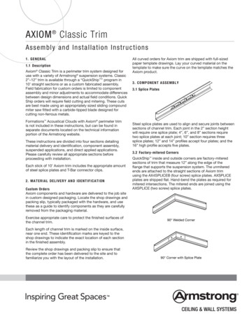
AXIOM Transitions Assembly and Installation Instructions1. GENERAL1.1 DescriptionAxiom Transitions trim simplifies the construction of drywall perimeterssurrounding Tegular or Vector ceiling panels. Flush Transitions areused between two ceiling planes at the same height accommodatingacoustical-to-acoustical, acoustical-to-drywall, and drywall-to-drywall.Our Field Transition is used in place of a bulkhead when you aretransitioning between two ceiling systems or changing ceiling systemdirection. We also provide elevation change options when there is aheight transition less than 10".Axiom Transitions trim with Vector panelto drywall perimeter (AXTRVESTR)Flush Transitions can be straight or curved eliminating the verticaldrywall return at the transition providing a perfect fit and finishevery time.unit gridAXTRVESTR is available in 10-foot long straight sections only andis used with full module installations of Vector ceiling panels. It is2-9/16" high.Above is the typical installation of the Axiom Transitions (no elevationchange) components. The versions for Tegular panels can be usedwith full-size or cut ceiling panels.Armstrong Touch-up Paint may be required for cut ceiling panels –Item# 5760 (8 oz) or 5761 (16 oz).These Axiom Transitions components feature an integrated tapingflange that simplifies the finishing of the drywall edge.AX15DSCSTR and AX15SDCCUR are for acoustical-to-acoustical flushtransitions. These are great transition pieces to tie different systems orlayouts together, and can be curved horizontally.AX15DSCSTRHanger Wireto stical PanelAXTBCHanger Wireto l Panel
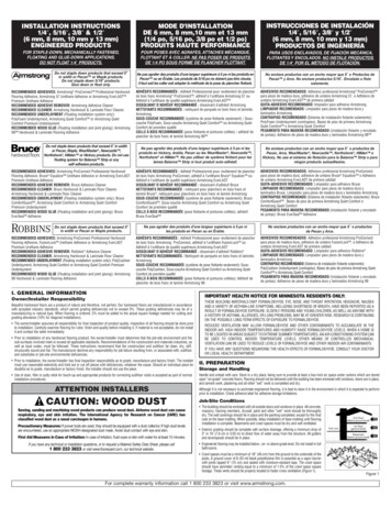
DrywallMain BeamAXCCLT Straight:Curved:AXTR7901STR AXTR7901CURAXTR7902STR AXTR7902CURAXTR7904STR AXTR7904CURAXTR7905STR AXTR7905CURAXTR7906STR AXTR7906CURAXTR7907STR AXTR7907CURAXTR7908STR AXTR7908CURAXTR7909STR AXTR7909CURAXTR7910STR AXTR7910CURAXTR7911STR AXTR7911CURAXTR7912STR AXTR7912CURAX15DSCSTR AX15DSCCURDrywallMain BeamAXCCLT5/8" GypsumBoardThese instructions are divided into four sections detailingmaterial delivery and identification, component assembly, installation,and final detailing. Please carefully review all appropriate sectionsbefore proceeding with installation.2. MATERIAL DELIVERY AND IDENTIFICATION2.1 DeliveryReview the packing slip to ensure that the complete order has beendelivered to the site.2", 4", 6", 8",10" Axiom TransitionsTrimLay-in PanelAcousticalAcoustical Lay-in Panel5/8" GypsumDrywall-to-Acoustical BoardAxiom DrywallBottom Trim – AXBTSTRPrelude XL Main BeamAcoustical Lay-in Panel2", 4", 6", 8",10" Axiom Transitions TrimAXCCLTPrelude XLMain Beam AXCCLT2", 4", 6", 8",10" Axiom Transitions TrimAcousticalLay-in PanelDrywallPrelude XL Main Main BeamBeamAcousticalLay-in PanelPrelude XL Main BeamAXCCLTDrywallMainBeam2", 4", 6", 8",10" Axiom 5/8" allDrywallMainBeam2", 4", 6", 5/8"8", Gypsum Board10" Axiom Transitions Trim AcousticalLay-in PanelAcousticalLay-in PanelHanger Wireto StructureDrywallMainPrelude XLCross TeeBeamAXCCLTDrywall MainBeam5/8" Gypsum Board2", 4", 6", 8",10" Axiom Transitions TrimAcoustical Lay-in PanelTrim –AXTR10STR2", 4", 6", 8",10" Axiom Transitions TrimAcoustical-to-AcousticalAXCCLTAxiom Transitions components and hardware are delivered to thejob site in specially designed packaging. Exercise appropriate care toprotect the finished surfaces of the channel trim.2.2 ReviewPrelude XL Main BeamPrelude XL Main BeamAxiom DrywallBottom Trim – AXBTSTRAxiom Transitions also accommodates elevation changes from 1" to 10".Acoustical-to-acoustical, acoustical-to-drywall, drywall-to-acoustical,and drywall-to-drywall transitions can be made in 2", 4", 6", 8", and 10"transitions. These transitions are available in 10-foot straight or curvedsections made to your shop drawings. The minimum bend radius on2"– 8" is 48", and the minimum bend radius on the 10" is 60".Straight: Curved:AXTR2STR – 2"AXTR2CUR – 2"AXTR4STR – 4"AXTR4CUR – 4"AXTR6STR – 6"AXTR6CUR – 6"AXTR8STR – 8"*AXTR8CUR – 8"AXTR10STR – 10"AXTR10CUR – 10"2", 4", 6", 8",10" Axiom Transitions Trim5/8" GypsumBoardDrywallPrelude XL MainDrywallBeamAxiomMain BeamBottom Trim – AXBTSTRAXCCLT2", 4", 6", 8",10" Axiom Transitions TrimAxiom DrywallBottom Trim – AXBTSTRDrywall MainBeamAxiom DrywallBottom Trim – AXBTSTRAXCCLT2", 4",5/8"6", 8",Gypsum Board10" Axiom Transitions Trim5/8" Gypsum BoardAxiom DrywallBottom Trim – AXBTSTR5/8" Gypsum BoardDrywall-to-Drywall2
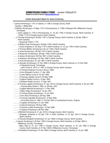
3. COMPONENT ASSEMBLY3.1 Splice PlatesSteel splice plates are used to align and secure all joints betweensections of Axiom Transitions trim. Each joint will require one splice.Splice plates are secured to the trim sections using factory-installedscrews.Typical procedure3.1.1 Position the splice plate (AXSPLICE2) in the bosses on the insideof the trim.3.1.2 Tighten the screws that secure the splice to the trim.3.2 T-Bar Connector ClipsThere are three versions of the T-Bar connector clip that can be usedwith the 7900 series items (1" transition or less) and the AX15DSC: The AXTBC is used in installations where the grid will rest flushon the Axiom flange (e.g. drywall, square lay-in, full size Vector and Tegular panels), or need to be raised 1/4" (e.g. cut Tegularpanels, Silhouette and Interlude suspension system). One clipis required at each location where thesuspension systemintersects the channel trim. The AXVTBC is used in installations where the grid will need tobe raised 3/8" or 1/2" (cut Vector panels). The AXVTBC must berequested at the time of order in lieu of the AXTBC clips. Oneclip is required at each location where the suspension systemintersects the channel trim.AXSPLICE2 Splice Plate The ATC (Adjustable Trim Clip; item 7239) can be used in variousinstallations to accommodate a range of grid offsets. This clipcan be adjusted to install grid at 0" to 3-3/4" above the flangeof the Axiom trim at 1/8" increments. This adjustability enablesAxiom Transitions to be installed with a range of WoodWorks ,MetalWorks , and other Architectural Specialties products. TheATC must be requested at the time of order in lieu of the AXTBCclips. One clip is required at each location where the suspensionsystem intersects the channel trim.All installations with the following elevation change items: AXTR2STR,AXTR2CUR, AXTR4STR, AXTR4CUR, AXTR6STR, AXTR6CUR,AXTR8STR, AXTR8CUR, AXTR10STR, and AXTR10CUR will ship withthe AXCCLT for connection to the grid system. One clip is required ateach location where the suspension system intersects the channel trim.3
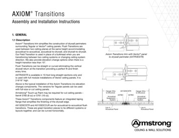
Alignment MarkT-Bar Connector Clips are attached to the suspension system membersusing screws supplied by the installer. Framing screws (#6 x 7/16" or1/2" lg.) are typical.Typical procedureReview the packing slip to ensure that the complete order has beendelivered to the site.3.2.1 Cut suspension system to length.3.2.2 Attach clip to suspension system member.3.2.3 Engage clip in channel bosses and tighten locking screw.4. GENERAL INSTALLATION PROCEDURES FOR ALL STRAIGHTAND CURVED AXIOM TRANSITIONS TRIMSAlignment MarkRest Clip on SuspensionSystem FlangeRest bottom of clipon flange ofsuspension system4.1 Lay out and install the suspension system according to the reflectedceiling plan.4.2 Attach the T-Bar Connector Clips4.2.1 Align clips as shown in section 3.2.4.2.2 Insert one framing screw near the center of the slot.4.3 Install the Axiom Transitions4.3.1 Hang the sections of trim onto the suspension system byengaging the top ear of the connector clips under the boss of thechannel trim. Slide the back plate downward to engage the lower bosson the trim and secure by tightening the locking screw.NOTE: It may be helpful to drill holes into the Axiom Transitions trim(no elevation change) and hang before cutting the suspension systemin place.4.3.2 Install the drywall grid system using additional AXTBC clips tocomplete the installation of the suspension system.4.3.3 Complete the installation of all channel trim sections. Install andsecure the splices.4.3.4 Make adjustments as necessary to properly align the completeinstallation. Insert a second framing screw in each of the connector clips.4.4 Add additional hanger wires as required4.4.1 The manufacturer requires that Axiom systems and theirsupporting suspension systems be installed and supported in a mannerthat complies with all applicable codes and standards. Typically thiswill require the use of #12 gauge galvanized, soft annealed steel wire orequivalent. Specification and approval of alternate materials should beby design professionals familiar with the project. Wire wraps should betight and neat.4Reference MarkSnap off bottomportion of clip andrest on grid flange
3/4"4.4.2 Main beams must be supported four feet on center or bycalculation based on actual ceiling weight.4.4.3 Cross tees located on each side of an end detail trim must besupported by wires located not more than 8" from the trim.4.4.4 Installations in areas requiring seismic restraint must have wiresattached to each suspension system member within 8" of the cut end.This practice is highly recommended for all installations. Lateral forcebracing shall be consistent with locally approved standards, or asdetailed in the specifications.4.4.5 Some seismic installations may classify the trim elements as"items" and require independent support from the building structure. Inthis situation, two hanger wires, connected to hanging clips (AX2HGC)or through holes drilled through to web of the Axiom Transitions trim,will be required for each section of channel trim.4.4.6 Install, finish, and paint 5/8" thick drywall panels.4.4.7 Install ceiling panels after all drywall work is completed.4.4.8 Color exposed cut edges of cut panels to match factory finish.1-11/16"1-1/2"AX2HGC Hanging ClipTapable Flange Installation1. Install the moldings after the gypsum board is mounted in place.2. Provide backing so that the moldings may be attached with #6drywall screws 16" O.C. for horizontal applications.3. Prior to taping, the attachment flanges should be cleaned usinga non-abrasive cleaner and soft rag. When veneer plaster isspecified, the flanges must be treated with a bonding agent.4. Be sure the tape does not overlap the edge of the reveal and an8" wide trowel is used to apply the final skim coat.NOTE: Fiberglass self-adhesive drywall tape will reduce taping timeand help avoid possible cracking.5
5. GENERAL INSTALLATION PROCEDURES – AXTRVESTR5.1 Lay out and install the suspension system according to thereflected ceiling plan.5.2 Cut and install the suspension system to maintain precisely23-1/16" between the outer edge of the 15/16" T-Bar suspension systemand the inner edge of the Axiom Transitions trim.5.3 Continue installation as detailed in sections 4.2 through 4.4.6.5.4 Install Vector ceiling panels6. FINAL DETAILING6.1 Check and adjust the alignment of Axiom components andceiling panels.6.2 Clean exposed surfaces as required. Painted Axiomcomponents may be wiped down with a mild household cleaner toremove fingerprints, oil, etc.6.3 Touch up painted components as required.M ORE IN F ORM AT I O NFor more information, or for an Armstrong Ceilings representative, call 1 877 276 7876.For complete technical information, detail drawings, CAD design assistance, installation information, andmany other technical services, call TechLine customer support at 1 877 276 7876 or FAX 1 800 572 TECH.Inspiring Great Spaces is a registered trademark of AFI Licensing LLC; All other trademarks used hereinare the property of AWI Licensing LLC and/or its affiliates. 2020 AWI Licensing Company Printed in the United States of AmericaBPLA-295816-520
4.4.2 Main beams must be supported four feet on center or by calculation based on actual ceiling weight. 4.4.3 Cross tees located on each side of an end detail trim must be supported by wires located not more than 8" from the trim. 4.4.4 Installations in areas requiring seismic restraint must have wires attached to each suspension system member within 8" of the cut end.