Transcription
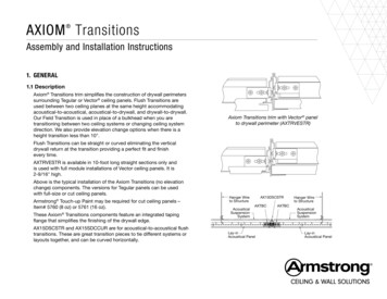
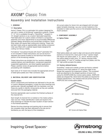
AXIOM Classic TrimA s s e m b ly and I nst al l at i on In str u ction s1 . GE N E RAL1.1 DescriptionAxiom Classic Trim is a perimeter trim system designed foruse with a variety of Armstrong suspension systems. Classic2”–12” trim is available through a “QuickShip ” program in10’ straight sections or as a custom fabricated assembly.Field fabrication for custom orders is limited to componentassembly and minor adjustments to accommodate differencesbetween design dimensions and actual field conditions. QuickShip orders will require field cutting and mitering. These cutsare best made using an appropriately sized sliding compoundmiter saw fitted with a carbide-tipped blade designed forcutting non-ferrous metals.Formations Acoustical Clouds with Axiom perimeter trimis not included in these instructions, but can be found inseparate documents located on the technical informationportion of the Armstrong website.These instructions are divided into four sections detailingmaterial delivery and identification, component assembly,suspended applications, and direct applied applications.Please carefully review all appropriate sections beforeproceeding with installation.Each stick of 10’ Axiom trim includes the appropriate amountof steel splice plates and T-Bar connector clips.2 . M AT E RIAL D E L I V ER Y A N D I D E N T I F I C A T I O NCustom OrdersAxiom components and hardware are delivered to the job sitein custom designed packaging. Locate the shop drawings andpacking slip, typically packaged with the hardware, and usethese as a guide to identify components as they are carefullyremoved from the packaging material.Exercise appropriate care to protect the finished surfaces ofthe channel trim.All curved orders for Axiom trim are shipped with full-sizedpaper template drawings. Lay your curved material on thetemplate to make sure the curve on the template matches theAxiom product.3 . COMP ONENT AS S EMBL Y3.1 Splice PlatesSteel splice plates are used to align and secure joints betweensections of channel trim. Each joint in the 2” section heightwill require one splice plate; 4”, 6”, and 8” sections requiretwo splice plates at each joint; 10” section requires threesplice plates; 12” and 14” profiles accept four plates; and the16” high profile accepts five plates.3.2 Factory-mitered CornersQuickShip inside and outside corners are factory-miteredsections of trim that measure 12” along the edge of theflange that supports the suspension system. The unmiteredends are attached to the straight sections of Axiom trimusing the AX4SPLICEB (four screw) splice plates. AXSPLICEplates are shipped flat. Hand-bend the plates as required formitered intersections. The mitered ends are joined using theAXSPLICE (two screw) splice plates.90 Welded CornerEach length of channel trim is marked on the inside surface,near one end. These identification marks are keyed to theshop drawings to indicate the exact location of each sectionin the finished assembly.Review the shop drawings and packing slip to ensure thatthe complete order has been delivered to the site and tofamiliarize you with the layout of the installation.90 Corner with Splice Plate
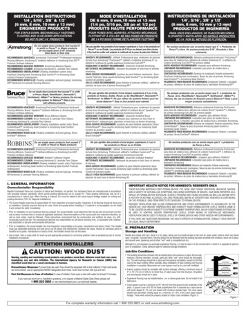
Outside corner posts ship pre-assembled with the splice platealready built into the product. The ends are attached to thestraight sections of Axiom trim using the AXSPLICE (twoscrew) splice plates that are built into the product.Outside Corner PostInside Corner PostThere are two versions of the T-Bar connector clip. AXTBCis used with drywall, lay-in, Tegular, concealed tile, andinstallations of Vector panels that are all full size. AXVTBC isused with cut Vector panels.AX-V-TBC clips are used with cut Vector panels and mustbe requested at the time of order in lieu of the AXTBC clips.Please see Section 4 of this guide and the Axiom ClassicPerimeter Trim Assembly Quick Reference Guide BPLA-295829for additional interface details.Insert splice plate in jointand close to about 1/2"T-Bar connector clips are attached to the suspension systemmembers using screws supplied by the installer. Framingscrews (#6 x 7/16” or 1/2” lg.) are typical. Special conditionssuch as open cell installations may dictate the use of alternatemethods of attachment.See detail drawings for alignment of the connector clip withthe suspension system member.Close joint and tighten setscrewsSplice plates are secured to the trim sections using factoryinstalled setscrews.CAUTION: Do not overtighten these screws. Applyonly enough force to lock the components together.Overtightening the screws can deform the exposed faceof the channel trim.Typical procedure1. Insert splices into channel trim bosses2. Close the joint3. Tighten screwsTypical procedure1. Cut suspension system to length2. Attach clip to suspension system member3. Engage clip in channel bosses and tighten locking screw3.4 Axiom Alignment ClipsAxiom Alignment Clips, AXAC, are used to align suspensionsystem members that extend beyond the lower edge of thetrim. These clips should not be used in the load path for anyapplication. These aluminum clips are supplied with a factoryinstalled screw that locks the clip in position and are orderedseparately.3.3 T-Bar Connector ClipsT-Bar connector clips are used to attach the channel trim tothe supporting suspension system members. These two-piecesteel clips are supplied as an assembled unit with the steellocking screw factory installed. One clip is required at eachlocation where the suspension system intersects thechannel trim.The clip is secured to the web of the suspension systemmembers using a standard framing screw supplied by theinstaller. One clip is required at each suspension system/channel intersection.Typical procedure1. Rotate hanging clips into the channel trim bosses2. Tighten clamping screw3. Install framing screw to attach clip to suspension system2
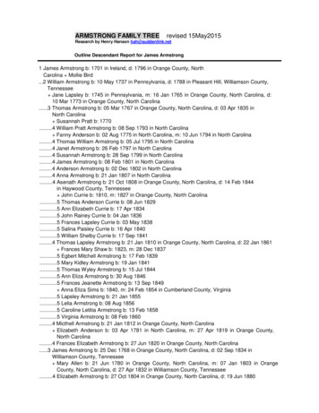
3.5 Direct Load Hanging ClipsDrywall trim is fastened using standard drywall screwsapplied through the tapping flange of the trim into the drywallsuspension system. After installation, the trim is finishedusing standard drywall materials and techniques. Normally,the drywall and Axiom trim is then painted to meet jobrequirements.Direct Load Hanging Clips, AX2HGC, are used whensuspension wires must be attached directly to the trimsections. Typical installations have the wires attachedto the suspension system and it supports the Axiom trim.The weight of the 10”, 12”, 14”, and 16” Axiom trimnecessitates that they be supported directly to structure.Typical procedure1. Install drywall suspension system andAxiom channel trim2. Attach 5/8” drywall to the system3. Install Axiom drywall trim4. Tape and finish drywall5. Paint3.7 Metal Panel Hold Down ClipsMetal panel hold down clips are used to secure the cut edgesof metal ceilings at the Axiom trim. Insert one clip for every footof perimeter, or as needed, to maintain contact between thepanel edge and the flange of the trim. These clips are orderedseparately.Typical procedure1. Rotate hanging clips into the channel trim bosses2. Tighten clamping screw3. Attach hanger wireInsert the top of the clip into the channel first. Pressup to compress the clip and insert the bottom leg into thechannel.3.6 Drywall TrimDrywall trim is used to finish the edges of 5/8” drywall that areapplied to the bottom surface of an Axiom installation. Drywalltrim sections can be factory formed to match the contour of theAxiom channels to which they are applied. These componentsare keyed to the shop drawings to identify the location of eachpiece in the assembly.Hanger WireDrywall GridSystem3.8 Suspended ApplicationsAXTBCSuspended applications of Axiom trim are those in which theAxiom perimeter trim and the suspension system that supportsit are installed in a manner that creates a space between theAxiom trim and the structure above and surrounding objects.These installations are often referred to as “clouds” and maybe as simple as a square or rectangle of free-floating ceiling,or as complex as a free-form shape or symbol. SuspendedAxiom applications may be purely aesthetic, or may be used toconceal overhead services or indirect lighting.AX1PC4STR5/8" DrywallOne-piece Drywall TrimTypical procedure1. Lay out and install the suspension systems according tothe reflected ceiling plan.a. Plan your suspension system layout to maximizethe length of cross tees that will support Axiomcomponents.Axiom Channel Trimb. Some of these cross tees will have to have hanger wiresattached to them. Longer cross tees will, in some cases,allow the wires to be located further away from theAxiom trim and, therefore, be less visible.Axiom BottomDrywall Trim(AXBTSTRWH) Straight(AXBTCURWH) CurvedTwo-piece Drywall Trim3
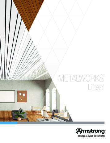
2. Brace and square the suspension system.4. Attach the T-Bar connector clips.a. Although not absolutely necessary, this stepwill greatly increase the speed and accuracy ofcompleting the remainder of the installation, and ishighly recommended.a. Remove the Axiom components and cut thesuspension system members as marked.b. Follow these guidelines for vertical location ofthe clips on the web of the suspension systemmembers:b. The suspension system can be braced diagonallyto the structure above using either splayed wires,or rigid bracing members such as angles or “C”channels. In either case, install bracing in the planeof both main beams and cross tees.b.1. T-Bar suspension system that will rest on thelower flange of the Axiom trim – use AXTBC.c. Squaring can be accomplished by temporarilyclamping a rigid member (main beam or wall angle)diagonally across the topside of the suspensionsystem to maintain 90 alignment of the mainbeams and cross tees.Alignment Markd. An alternate method is to cut scrap suspensionsystem components to fit diagonally into the ceilingmodule. When installed in pairs, these short bracesare effective during layout and installation, andcan be reinstalled on top of the ceiling panels tomaintain alignment of the system.Rest Clip on SuspensionSystem Flangee. For small installations, it may be preferable toassemble, mark, and cut the suspension systemcomponents on the floor, and then suspend andbrace the suspension system.3. Assemble and position the Axiom components on topof the suspension system.a. Temporarily assemble the Axiom componentsresting on top of the suspension system. Checkalignment and clamp the components in place.b. Mark the location where the open side of theAxiom channel trim rests on the suspensionsystem members. This mark will be used for initialalignment of the T-Bar connector clip.b.2. Silhouette XL , Interlude XL HRC, andSonata (systems with a 5/16” shoulder height),Tegular panels on Prelude or Suprafine withthe panel face resting on the trim flange, and5/8” concealed tile – use AXTBC.Alignment MarkReference MarkSnap off Tab, Rest Clip onSuspension System FlangeCut Mark - 1/4" to 3/8"Beyondc. Make a second mark 1/4” to 3/8” closer to the faceof the Axiom channel trim. This second mark iswhere the suspension system members will be cut.The 3/8” dimension is the maximum length that thesuspension system member can extend into thechannel trim. Use of the 1/4” dimension allows moreadjustment during final assembly.4
b.3. MetalWorks Vector (cut panels only) and3/4” concealed tile – use AXVTBC.6. Add additional hanger wires as required.a. The manufacturer requires that Axiom systems andtheir supporting suspension systems be installedand supported in a manner that complies to allapplicable codes and standards. Typically, thiswill require the use of #12 gauge galvanized, softannealed steel wire or equivalent. Specification andapproval of alternate materials should be by designprofessionals familiar with the project. Mechanicsshould exercise care in the application of hangersto minimize the visual impact on the finishedinstallation. Wire wraps should be tight and neat,and where appropriate, the wires may be painted toblend into the background as much as possible.Alignment MarkRest Clip on SuspensionSystem Flangeb. Main beams must be supported 4’ on center or bycalculation based on actual ceiling weight.c. Cross tees located on each side of a joint inthe channel trim and then at 4’ centers must besupported by wires located closer to the channeltrim than their midpoint.b.4. Ultima , Optima , and WoodWorks Vector AlignmentMark(cut panels)– useAXVTBC.d. Installations in areas requiring seismic restraintmay require wires attached to each suspensionsystem member within 8” of the cut end. Thispractice is highly recommended for all installations.Lateral force bracing shall be consistent withlocally approved standards, or as detailed in thespecifications.Alignment MarkSnap off Tab, Rest Clip onSuspension System FlangeSnap off Tab, Rest Clip onSuspension System Flangee. Axiom Classic 10”, 12”, 14”, and 16” profiles mustbe supported directly from the structure using twoAX2HGC clips per section of trim and must beordered separately.7. Install ceiling panels, tile, or drywall.a. Cut and install tiles or panels using standardprocedures for the specified products.c. Attach the clips by aligning the end of the elongatedhole with the reference mark on the suspensionsystem and inserting a standard framing screw intothe center of the slot.b. Treat exposed cut edges of ceiling panels asdetailed in the project specifications.c. For drywall applications, attach 5/8” gypsum panelsto the suspension system per the manufacturer’srecommendations.5. Install the Axiom channel trim.a. Hang the sections of channel trim onto thesuspension system by engaging the top ear ofthe connector clips under the boss of the channeltrim. Slide the lower leg downward to engage thelower boss on the trim and secure by tightening thelocking screw.NOTE: The drywall bottom trim is designed toaccommodate the full thickness of standard 5/8”drywall only. Lay out the position of the drywallpanels to prevent tapered edges from falling at thelocation of the Axiom trim. Trim edges by applyingthe Axiom drywall bottom trim, screwed through theface of the gypsum panel and into the supportingsuspension system members. Finish and paintusing standard materials and techniques.b. Complete the installation of all channel trimsections. Install and secure the splice plates.c. Adjust the trim as necessary to properly align thecompleted installation. Insert a second framingscrew through the round hole in each of theconnector clips.5
3.9 Brace 10”, 12”, 14”, and 16” Channel Trims2. Attach the channel trim sections to the structure.The 10”, 12”, 14”, and 16” high profiles require diagonalbracing to keep the face of the trim vertical. The spacingof this bracing will be dependent on the layout of theAxiom trim. Straight sections should be braced every 4’.Radius sections will require less bracing as the radius becomessmaller.a. Insert appropriate length screws through the top flangeof the channel trim sections and into the supportingmembers.Fabricate the braces from the T-Bar suspension system andattach to the trim as shown below.c. Adjust the location of channel trim sections as required.b. Install splice plates and, where required, hanging clipsas the work progresses.3. Cut and install the specified suspension system to completethe installation.a. Prepare the T-Bar connector clips as described inSection 3.3. for suspended applications.b. Install T-Bar connector clips in the Axiom channels.c. Cut and install suspension system members and attachto T-Bar connector clips using standard framing screws.4. Complete the installation of ceiling panels or drywallas described in Step 7 of Section 3.8. for suspendedapplications.3.10 Direct Applied ApplicationsDirect applied applications of Axiom are those in which theAxiom perimeter trim components are attached by screwingdirectly to a drywall or acoustical ceiling suspension system.The following section details the procedures to be followed forthis type of installation.Typical procedure1. Lay out the pattern on the face of the supporting system.a. Drywall surfaces should be taped and sanded beforeapplication of the Axiom components.b. Trace the pattern onto the drywall. Note that when radiussections are shown on the shop drawings, the dimensionis always measured from the face of the Axiom channel.4 . F INAL DET AIL ING4.1 Check and adjust the alignment of Axiom components andceiling panels.4.2 Clean exposed surfaces as required. Painted Axiomcomponents may be wiped down with a mild householdcleaner to remove fingerprints, oil, etc.4.3 Touch up painted components as required. All paintedcustom Axiom shipments include a container of paint to beused for this purpose. Drywall systems are supplied with aconversion coating factory applied. After assembly, taping, andfinishing, the Axiom components and drywall are field-paintedaccording to specification.c. Lay acoustical panels or pieces of drywall into exposedsuspension systems to provide enough surface area toaccurately trace the pattern.M ORE IN FORM AT I O NFor more information, or for an Armstrong representative, call 1 877 ARMSTRONG.For complete technical information, detail drawings, CAD design assistance, installation information, and manyother technical services, call TechLineSM customer service at 1 877 armstrong or FAX 1 800 572 TECH.For the latest product selection and specification data, visit armstrong.com/axiom.All trademarks used herein are the property of AWI Licensing Company and/or its affiliates 2015 AWI Licensing Company Printed in the United States of AmericaBPLA-295048-1215 6
AXIOM Classic Trim Assembly and Installation Instructions 1. GENERAL 1.1 Description Axiom Classic Trim is a perimeter trim system designed for use with a variety of Armstrong suspension systems. Classic 2"-12" trim is available through a "QuickShip " program in 10' straight sections or as a custom fabricated assembly.