Transcription
LATERAL-TORSIONAL BUCKLING OF STRUCTURES WITH MONOSYMMETRICCROSS-SECTIONSbyMatthew J. VenskoB.S. Pennsylvania State University, 2003Submitted to the Graduate Faculty of theSwanson School of Engineering in partial fulfillmentof the requirements for the degree ofMaster of ScienceUniversity of Pittsburgh2008
UNIVERSITY OF PITTSBURGHSWANSON SCHOOL OF ENGINEERINGThis thesis was presentedbyMatthew J. VenskoIt was defended onNovember 21, 2008and approved byKent A. Harries, Assistant Professor,Department of Civil and Environmental EngineeringAlbert To, Assistant Professor,Department of Civil and Environmental EngineeringMorteza A. M. Torkamani, Associate Professor,Department of Civil and Environmental Engineering,Thesis Advisorii
LATERAL-TORSIONAL BUCKLING OF STRUCTURES WITH MONOSYMMETRICCROSS-SECTIONSMatthew J. Vensko, M.S.University of Pittsburgh, 2008Lateral-torsional buckling is a method of failure that occurs when the in-plane bending capacityof a member exceeds its resistance to out-of-plane lateral buckling and twisting. The lateraltorsional buckling of beam-columns with doubly-symmetric cross-sections is a topic that hasbeen long discussed and well covered. The buckling of members with monosymmetric crosssections is an underdeveloped topic, with its derivations complicated by the fact that the centroidand the shear center of the cross-section do not coincide. In this paper, the total potential energyequation of a beam-column element with a monosymmetric cross-section will be derived topredict the lateral-torsional buckling load.The total potential energy equation is the sum of the strain energy and the potentialenergy of the external loads. The theorem of minimum total potential energy exerts that settingthe second variation of this equation equal to zero will represent a transition from a stable to anunstable state. The buckling loads can then be identified when this transition takes place. Thisthesis will derive energy equations in both dimensional and non-dimensional forms assumingiii
that the beam-column is without prebuckling deformations. This dimensional buckling equationwill then be expanded to include prebuckling deformations.The ability of these equations to predict the lateral-torsional buckling loads of a structureis demonstrated for different loading and boundary conditions. The accuracy of these predictionsis dependent on the ability to select a suitable shape function to mimic the buckled shape of thebeam-column. The results provided by the buckling equations derived in this thesis, using asuitable shape function, are compared to examples in existing literature considering the sameboundary and loading conditions.The finite element method is then used, along with the energy equations, to deriveelement elastic and geometric stiffness matrices. These element stiffness matrices can betransformed into global stiffness matrices. Boundary conditions can then be enforced and ageneralized eigenvalue problem can then be used to determine the buckling loads. The elementelastic and geometric stiffness matrices are presented in this thesis so that future research canapply them to a computer software program to predict lateral-torsional buckling loads ofcomplex systems containing members with monosymmetric cross-sections.iv
TABLE OF CONTENTS1.0 INTRODUCTION.12.0 LITERATURE REVIEW.42.1 EQUILIBRIUM METHOD.52.1.1Closed Form Solutions.72.2 ENERGY METHOD.182.2.1Uniform Torsion.192.2.2Non-Uniform Torsion.202.2.3Strain Energy.212.2.4Solutions Using Buckling Shapes.233.0 LATERAL-TORSIONAL BUCKLING OF BEAM-COLUMNS.283.1 STRAIN Stresses and Stress Resultants.433.1.4Section Properties.443.2 STRAIN ENERGY EQUATION FOR MONOSYMMETRIC BEAMCOLUMNS.453.3 POTENTIAL ENERGY OF THE EXTERNAL LOADS.463.3.1Displacements and Rotations of Load Points.47v
3.4 ENERGY EQUATION FOR LATERAL TORSIONAL BUCKLING.493.5 NON-DIMENSIONAL ENERGY EQUATION.514.0 LATERAL-TORSIONAL BUCKLING OF MONOSYMMETRIC BEAMSCONSIDERING PREBUCKLING DEFLECTIONS.544.1 STRAIN ENERGY CONSIDERING PREBUCKLING al Strain.554.1.3Shear Strain.584.2 STRAIN ENERGY EQUATION CONSIDERING PREBUCKLINGDEFLECTIONS.584.3 POTENTIAL ENERGY OF THE EXTERNAL LOADS CONSIDERINGPREBUCKLING DEFLECTIONS.594.3.1Displacements and Rotations of Load Points.594.4 ENERGY EQUATION CONSIDERING PREBUCKLING DEFLECTION.605.0 APPLICATIONS.645.1 SIMPLY-SUPPORTED MONOSYMMETRIC BEAM SUBJECTED TO EQUALEND MOMENTS, M.645.2 SIMPLY-SUPPORTED MONOSYMMETRIC BEAM SUBJECTED TOCONCENTRATED CENTRAL LOAD, P.705.3 SIMPLY-SUPPORTED MONOSYMMETRIC BEAM SUBJECTED TOUNIFORMLY DISTRIBUTED LOAD, q.795.4 CANTILEVER WITH END POINT LOAD, P.886.0 FINITE ELEMENT METHOD.986.1 ELASTIC STIFFNESS MATRIX.1046.2 GEOMETRIC STIFFNESS MATRIX.106vi
6.3 FINITE ELEMENT METHOD CONSIDERING PREBUCKLINGDEFLECTIONS.1096.4 ELASTIC STIFFNESS MATRIX CONSIDERING PREBUCKLINGDEFLECTIONS.1106.5 GEOMETRIC STIFFNESS MATRIX CONSIDERING PREBUCKLINGDEFLECTIONS.1127.0 SUMMARY.115APPENDIX A.118A.1 ELEMENT ELASTIC STIFFNESS MATRIX.118A.2 ELEMENT GEOMETRIC STIFFNESS MATRIX.120A.3 ELEMENT NON-DIMENSIONAL STIFFNESS MATRIX.126A.4 ELEMENT NON-DIMENSIONAL GEOMETRIC STIFFNESS MATRIX.128A.5 ELEMENT PREBUCKLING STIFFNESS MATRIX.134A.6 ELEMENT PREBUCKLING GEOMETRIC STIFFNESS MATRIX.136APPENDIX B.143B.1 MATRIX [A] FROM SECTION 5.4.143B.2 MATRIX [B] FROM SECTON 5.4.145BIBLIOGRAPHY.156WORKS CITED.156WORKS CONSULTED.158vii
LIST OF FIGURESFigure 2.1a Beams of Rectangular Cross-Section.6Figure 2.1b Beams of Rectangular Cross-Section with Axial Force and End Moments.6Figure 2.2 Linearly Tapered Beam Subjected to Equal and Opposite End Moments.9Figure 2.3 Simply-Supported Beam with Concentrated Load, P, at Midspan.11Figure 2.4a Monosymmetric Beam Subjected to End Moments and Axial Load.14Figure 2.4b Cross-Section of Monosymmetric Beam.14Figure 2.5 Twisting of Rectangular Beam Free to Warp.19Figure 2.6 I-Beam Subjected Fixed at Both Ends to End Moments.26Figure 3.1 Coordinate System of Undeformed Monosymmetric Beam.29Figure 3.2 External Loads and Member End Actions of Beam Element.30Figure 3.3 Cross-Section of Monosymmetric I-Beam.31Figure 3.4 Deformed Beam.34Figure 3.5 Translation of Point Po to Point P.35viii
Figure 5.1 Monosymmetric Beam with Subjected to Equal End Moments.65Figure 5.2 Monosymmetric Beam with Subjected to Concentrated Central Load.70Figure 5.3 Buckling Load: Simply Supported Beam with Monosymmetric Cross-SectionSubjected to a Concentrated Central Load ( βx 0.6) .75Figure 5.4 Buckling Load: Simply Supported Beam with Monosymmetric Cross-SectionSubjected to a Concentrated Central Load ( βx 0.3) .76Figure 5.5 Buckling Load: Simply Supported Beam with Monosymmetric Cross-SectionSubjected to a Concentrated Central Load ( βx 01. ) .76Figure 5.6 Buckling Load: Simply Supported Beam with Monosymmetric Cross-SectionSubjected to a Concentrated Central Load ( βx 0) .77Figure 5.7 Buckling Load: Simply Supported Beam with Monosymmetric Cross-SectionSubjected to a Concentrated Central Load ( βx 01. ) .77Figure 5.8 Buckling Load: Simply Supported Beam with Monosymmetric Cross-SectionSubjected to a Concentrated Central Load ( βx 0.3) .78Figure 5.9 Buckling Load: Simply Supported Beam with Monosymmetric Cross-SectionSubjected to a Concentrated Central Load ( βx 0.6) .78Figure 5.10 Monosymmetric Beam Subjected to a Uniformly Distributed Load.79Figure 5.11 Buckling Load: Simply Supported Beam with Monosymmetric Cross-SectionSubjected to a Uniformly Distributed Load ( βx 0.6) .84ix
Figure 5.12 Buckling Load: Simply Supported Beam with Monosymmetric Cross-SectionSubjected to a Uniformly Distributed Load ( βx 0.3) .84Figure 5.13 Buckling Load: Simply Supported Beam with Monosymmetric Cross-SectionSubjected to a Uniformly Distributed Load ( βx 01. ) .85Figure 5.14 Buckling Load: Simply Supported Beam with Monosymmetric Cross-SectionSubjected to a Uniformly Distributed Load ( βx 0) .85Figure 5.15 Buckling Load: Simply Supported Beam with Monosymmetric Cross-SectionSubjected to a Uniformly Distributed Load ( βx 01. ) .86Figure 5.16 Buckling Load: Simply Supported Beam with Monosymmetric Cross-SectionSubjected to a Uniformly Distributed Load ( βx 0.3) .86Figure 5.17 Buckling Load: Simply Supported Beam with Monosymmetric Cross-SectionSubjected to a Uniformly Distributed Load ( βx 0.6) .87Figure 5.18 Monosymmetric Cantilever Beam Subjected to a Concentrated End Load.88Figure 5.19 Buckling Load: Cantilever Beam with Monosymmetric Cross-Section Subjected to aConcentrated End Load ( βx 0.6) .94Figure 5.20 Buckling Load: Cantilever Beam with Monosymmetric Cross-Section Subjected to aConcentrated End Load ( βx 0.3) .95Figure 5.21 Buckling Load: Cantilever Beam with Monosymmetric Cross-Section Subjected to aConcentrated End Load ( βx 01. ) .95x
Figure 5.22 Buckling Load: Cantilever Beam with Monosymmetric Cross-Section Subjected to aConcentrated End Load ( βx 0) .96Figure 5.23 Buckling Load: Cantilever Beam with Monosymmetric Cross-Section Subjected to aConcentrated End Load ( βx 01. ) .96Figure 5.24 Buckling Load: Cantilever Beam with Monosymmetric Cross-Section Subjected to aConcentrated End Load ( βx 0.3) .97Figure 5.25 Buckling Load: Cantilever Beam with Monosymmetric Cross-Section Subjected to aConcentrated End Load ( βx 0.6) .97Figure 6.1 Element Degrees of Freedom with Nodal Displacements u.100Figure 6.2 Element Degrees of Freedom with Nodal Displacements v.100Figure 6.3 Element Degrees of Freedom with Nodal Displacements φ .100xi
NOMENCLATURESymbolDescriptionAarea of memberadistributed load heightanon-dimensional distributed load height{D}global nodal displacement vector for the structure{De}global nodal displacement vector for an element{de}local nodal displacement vector for an elementEmodulus of elasticityeconcentrated load heightenon-dimensional concentrated load heightFaxial loadFnon-dimensional axial loadGshear modulusxii
[ge]element local geometric stiffness matrix for initial load set[ge]Pelement local geometrix stiffness matrix for prebucklinghdepth of the memberIxmoment of inertial about the x axisIymoment of inertial about the y axisIωwarping moment of inertiaJtorsional constantKbeam parameter[ke]element local stiffness matrix[ke]Pelement local stiffness matrix for prebucklingkztorsional curvature of the deformed elementLmember lengthMcrclassical lateral buckling uniform bending momentMxbending moment[N]shape function matrixPconcentrated loadPcrcritical concentrated loadxiii
γPnon-dimensional concentrated loadqdistributed loadqcrcritical uniformly distributed loadγqnon-dimensional distributed loadropolar radius of gyration about the shear centerronon-dimensional polar radius of gyration[Te]transformation matrix[Tr]rotation transformation matrixtpperpendicular distance to P from the mid-thickness surfaceUstrain energyUestrain energy for each finite elementuout-of-plane lateral displacementupout-of-plane lateral displacement of point Pou 1 , u3out-of-plane lateral displacements at nodes 1 and 2u2, u4out-of-plane rotation at nodes 1 and 2u’out-of-plane rotationunon-dimensional out-of-plane lateral displacementxiv
vin-plane bending displacementvMdisplacement through which the applied moment actsvPin-plane bending displacement of point Povqdisplacement through which the distributed load actsv1 , v3in-plane displacements at nodes 1 and 2v2 , v4in-plane rotation at nodes 1 and 2v’in-plane rotationwaxial displacementwFlongitudinal displacement through which the axial load actswPlongitudinal displacement of point Poy oshear center displacementnon-dimensional shear center displacementzPconcentrated load location from left supportznon-dimensional member distancezpnon-dimensional distance to concentrated loadβxmonosymmetry parameterβxnon-dimensional monosymmetry parameterxv
εPlongitudinal strain of point Poφout-of-plane twisting rotationφ 1, φ 3out-of-plane twisting rotation at nodes 1 and 2φ 2, φ 4out-of-plane torsional curvature at nodes 1 and 2φ’out-of-plane torsional curvatureγPshear strain of point Poλbuckling parameter total potential energynon-dimensional total potential energyρdegree of monosymmetryσPlongitudinal stress of point PoτPshear stress of point Poωwarping functionΩpotential energy of the loadsΩepotential energy of the loads for each finite elementθrotation of the member cross-sectionxvi
1.0 INTRODUCTIONThe members of a steel structure, commonly known as beam-columns, are usually designed witha thin-walled cross-section. Thin-walled cross-sections are used as a compromise betweenstructural stability and economic efficiency and include angles, channels, box-beams, I-beams,etc. These members are usually designed so that the loads are applied in the plane of the weakaxis of the cross-section, so that the bending occurs about the strong axis. However, when abeam, usually slender in nature, has relatively small lateral and torsional stiffnesses compared toits stiffness in the plane of loading, the beam will deflect laterally and twist out of plane whenthe load reaches a critical limit. This limit is known as the elastic lateral-torsional bucklingload.The lateral buckling and twisting of the beam are interdependent in that when a memberdeflects laterally, the resulting induced moment exerts a component torque about the deflectedlongitudinal axis which causes the beam to twist (Wang, et al. 2005). The lateral-torsionalbuckling loads for a beam-column are influenced by a number of factors, including crosssectional shape, the unbraced length and support conditions of the beam, the type and position ofthe applied loads along the member axis, and the location of the applied loads with respect to thecentroidal axis of the cross section.This paper will focus on the lateral-torsional buckling of steel I-beams with amonosymmetric cross-section. In a beam with a monosymmetric cross-section, the shear center1
and the centroid of the cross-section do not coincide. The significance of this can be explainedby the Wagner effect (Anderson and Trahair, 1972), in which the twisting of the member causesthe axial compressive and tension stresses to exert an additional disturbing torque. This torquecan reduce the torsional stiffness of a member in compression and increase the torsional stiffnessof a member in tension. In I-beams with doubly-symmetric cross-sections, these compressiveand tensile stresses balance each other exactly and the change in the torsional stiffness is zero. InI-beams with monosymmetric cross-sections where the smaller flange is further from the shearcenter, the Wagner effect results in a change in the torsional stiffness. The stresses in the smallerflange have a greater lever arm and predominate in the Wagner effect. The torsional stiffness ofthe beam will then increase when the smaller flange is in tension and decrease when the smallerflange is in compression.When a structure is simple, such as a beam, an energy method approach may be useddirectly to calculate the lateral-torsional buckling load of the structure. Assuming a suitableshape function, the equations derived using the energy method can provide approximate bucklingloads for the structure. However, when a structure is complex, this is not possible. In this case,the energy method in conjunction with the finite element method may be used to calculate thelateral-torsional buckling load of the structure.The finite element method is a versatile numerical and mathematical approach which canencompass complicated loads, boundary conditions, and geometry of a structure. First, elementelastic stiffness and geometric stiffness matrices are derived for an element using the energyequations for lateral-torsional buckling. The structure in question must be divided into severalelements, and a global coordinate system can be selected for that structure. The element elasticstiffness and geometric stiffness matrices are transformed to the global coordinate system for2
each element, resulting in global element elastic and geometric stiffness matrices for thestructure. After this assembly process, boundary conditions are enforced to convert the structurefrom an unrestrained structure to a restrained structure. The derived equilibrium equations are inthe form of a generalized eigenvalue problem, where the eigenvalues are the load factors that,when multiplied to a reference load, result in lateral-torsional buckling loads for the structure.The main objective of this thesis is to formulate equations for lateral-torsional bucklingof monosymmetric beams using the energy method. Suitable shape functions will be applied tothese equations to provide approximate buckling solutions that can be compared to previous data.The finite element method will be used to derive element elastic and geometric stiffness matricesthat can be used in future works in conjunction with computer software to determine lateraltorsional buckling loads of more complex structures.3
2.0 LITERATURE REVIEWThis section reviews available literature that explores lateral-torsional buckling as the primarystate of failure for beams used in structures. A beam that has relatively small lateral andtorsional stiffnesses compared to its stiffness in the plane of loading tends to deflect laterally andtwist out of plane. This failure mode is known as lateral-torsional buckling. Two methods areused to derive the critical load values that result in lateral-torsional buckling beam failure: themethod utilizing differential equilibrium equations and the energy method. The differentialequilibrium method of stability analysis assumes the internal and external forces acting on anobject to be equal and opposite. The energy method refers to an approach where the totalpotential energy of a conservative system is calculated by summing the internal and externalenergies. The buckling loads for the system can then be approximated if a suitable shapefunction for the particular structure is used, thus reducing the system from one having infinitedegrees of freedom to one having finite degrees of freedom. This approach is known as theRayleigh-Ritz method. This method will provide acceptable results as long as the assumed shapefunction is accurate. Both the differential equilibrium method and energy methods are examinedin this literature review.4
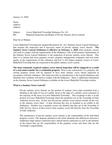
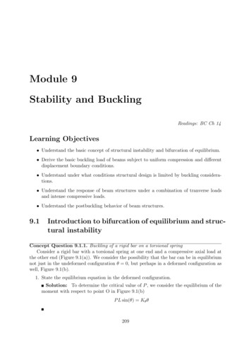
2.1EQUILIBRIUM METHODThe closed form solutions for various loading conditions and cross-sections are demonstratedbelow using the equilibrium method. The beams are assumed to be stationary and therefore thesum of the internal forces of the structure and the external forces is assumed to be zero. Theequations are rearranged in terms of displacements resulting in a second order differentialequation from which the buckling loads can be solved. The beams are assumed in this section tobe elastic, initially perfectly straight, and in-plane deformations are neglected. Rotation of thebeam, φ , is assumed small, so for the small angle relationships sin φ φ and cos φ 1 can beused.Consider a simply supported beam with a uniform rectangular cross section as shown inFigure 2.1a and Figure 2.1b. Note that u, v and w are the displacements in the x-, y-, and zdirections, respectively. The section rotates out of plane at an angle φ . The differentialequilibrium equations of minor axis bending and torsion of a beam with no axial force (F 0)are derived from statics as (Chen and Lui. 1987)EI yGJd2 u M xφdz 2(2.1)dφdu Mx Mzdzdzwhere EI y Ehb 312and GJ (2.2)Ghb 335
EI y represents the flexural rigidity of the beam with respect to the y-axis and GJ represents thetorsional rigidity of the beam with respect to the z-axis. M x and M z are the internal momentsof the beam acting about the x-axis and the z-axis, respectively. In Eq. (2.1), the component ofM x in the y-direction is represented by M x sin φ which, by way of the small angle theorem,reduces to M x φ . In Eq. (2.2), the torsional component of M x acting in the z-direction isrepresented by M xdu.dzbhzxyuFigure 2.1a Beams of Rectangular Cross-SectionMMFFzLyFigure 2.1b Beams of Rectangular Cross-Section with Axial Force and End Moments6
2.1.1 Closed Form SolutionsCase 1: A beam that is subjected to only equal end moments M about x-axisThis loading case is shown in Figure 2.1b, with F 0. Since there is no torsional component ofthe moment, let Mx M and Mz 0. The equilibrium equations given in Eq. (2.1) and (2.2)reduce tod2 uEI y M φdz 2(2.3)dφdu Mdzdz(2.4)GJSolving for u from Eqs. (2.3) and (2.4) yields (respectively):d 2 u Mφ EI ydz 2(2.5)d 2 u GJ d 2 φ M dz 2dz 2(2.6)Eliminating u yields a single differential equation of the formd 2φM2φ 0 dz 2 GJEI y(2.7)Solving the second order differential equation yields the general solution as φ ( z) A sin Mz B cos EI y GJ Mz EI y GJ By applying the boundary condition φ 0 at z 0, B is equal to zero.7(2.8)
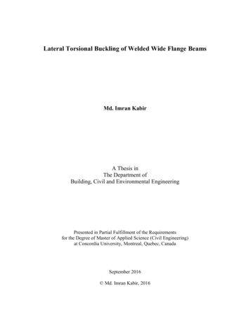
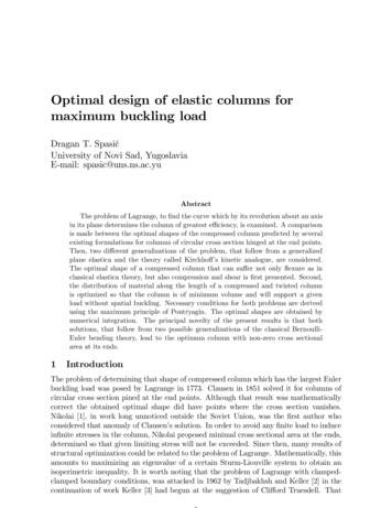
The constant A may then not be equal to zero because it provides a trivial solution. Therefore atz LsinM cr LEI y GJ 0(2.9)Solving for Mcr to provide the smallest nonzero buckling load yieldsM cr π EI y GJ(2.10)Lwhere Mcr is the critical value of M that will cause the beam to deflect laterally and twist out ofplane.Case 2: A linearly tapered beam with a rectangular cross section that is subjected to only equalend moments M about x-axisFor this case, consider a linearly tapered beam with initial depth ho which increases at a rateas shown in Figure 2.2 whereh( z ) (1 zδ )hoL(2.11)In Eq. (2.11), h(z) is the linear tapered depth of the beam as a function of z, ho is the depth ofbeam at z 0, and (1 δ) is the ratio of height of tapered beam at z L to z 0.8zδL
MMzhoh (z)(1 δ ) h oLyFigure 2.2 Linear Tapered Beam Subjected to Equal and Opposite End MomentsThe beam properties of the tapered section can be written asEI y EI oη(2.12)GJ GJ o η(2.13)ho b 3ho b 3zwhere I o , Jo , and η 1 δ .123L(2.14)As in Case 1, there is no torsional component of the moment so that Mx M and Mz 0.Substituting Eqs. (2.12) and (2.13) into the equilibrium equations yieldd 2uEI oη 2 Mφdz(2.15)dφdu Mdzdz(2.16)GJ o ηThe derivative of η with respect to z isdη δ dz L(2.17)which enables the following relationships9
(2.18)dφ dφ dη δ dφ dz dη dz L dηandd 2φ δ d 2φ dz 2 L dη 22(2.19)Substituting Eqs. (2.17) – (2.19) into the equilibrium Eqs. (2.15) and (2.16) yield2 δ d u MφEI o η L dη 2(2.20) δ dφ δ duGJ o η M L dη L dη(2.21)2Differentiating Eq. (2.21) and combining it with Eq.(2.20) in order to eliminate u yieldsd 2φdφη k 2φ 02 ηdηdη(2.22)M 2 L2k EI o GJ o δ 2(2.23)2where2The general solution of Eq. (2.22) is given by (Lee, 1959)φ A sin( k ln η) B cos( k ln η)(2.24)Applying the boundary condition φ 0 at z 0, B is equal to zero. The constant A may then notbe equal to zero because it provides a trivial solution. Therefore the boundary condition φ 0 atη (1 δ ) yieldssin( k ln(1 δ )) 0(2.25)Solving for Mcr to provide the smallest nonzero buckling load yields10
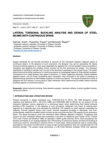
M cr πδEI o GJ oln(1 δ )L(2.26)where Mcr is the critical value of M that will cause the beam to deflect laterally and twist out ofplane. It is important to recognize that if δ 0 , meaning that the beam is not tapered, Eq. (2.26)reduces toM cr π EI o GJ o(2.27)Lwhich is the result obtained in Case 1.Case 3: A simply supported beam with a concentrated load, P, at midspan (at z L/2)For this case, consider a non-tapered beam with a concentrated load, P, at midspan as shown inFigure 2.3.PzLyFigure 2.3 Simply Supported Beam with Concentrated Load, P, at Midspan11
The moments Mx and Mz are derived using basic equilibrium concepts asMx Pz2(2.28)Mz P( u u)2(2.29)Where u* represents the lateral deflection at the centroid of the middle cross section and urepresents the lateral deflection at any cross section.By substituting the relationships for M x and M z into Eqs. (2.1) and
iii LATERAL-TORSIONAL BUCKLING OF STRUCTURES WITH MONOSYMMETRIC CROSS-SECTIONS Matthew J. Vensko, M.S. University of Pittsburgh, 2008 Lateral-torsional buckling is a method of failure that occurs when the in-plane bending capacity