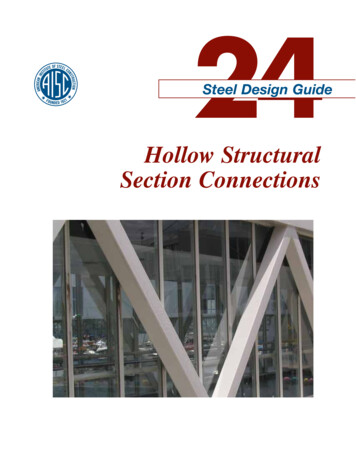
Transcription
manualwiseAn introduction to the newest edition ofAISC’s Seismic Design Manual.BRACED FORBETTER SEISMICDESIGNBY ERIC BOLIN, PE, ANDMICHAEL GANNON, SE, PEDO YOU DESIGN PROJECTS with seismic systems? If so, good news: AISC hasjust released the 3rd Edition Seismic Design Manual.This edition has been expanded with new discussion and design examples to helpengineers navigate the design of steel and composite Seismic Force Resisting Systems(SFRS). It includes discussion and practical guidance on applying the latest versionsof AISC’s core standards—the 2016 Specification for Structural Steel Buildings (ANSI/AISC 360), 2016 Seismic Provisions for Structural Steel Buildings (ANSI/AISC 341), 2016Prequalified Connections for Special and Intermediate Steel Moment Frames for Seismic Applications (ANSI/AISC 358) and the 15th Edition Steel Construction Manual.The new edition contains more than 60 examples that demonstrate how to designthe key members and connections for the most commonly used SFRS. The examplesgo beyond just seismic-specific checks to also demonstrate the full design, limit stateby limit state. The manual is a valuable resource not only for those who design in theseismic world, but for anyone interested in learning the procedures used for designingmembers, connections and systems.The overall organization of the Seismic Manual has not changed from the 2nd Edition, and the chapters are still organized as follows:Part 1: General Design ConsiderationsPart 2: AnalysisPart 3: Systems Not Specifically Designed for Seismic ResistancePart 4: Moment FramesPart 5: Braced FramesPart 6: Composite Moment FramesPart 7: Composite Braced Frames and Shear WallsPart 8: Diaphragms, Collectors and ChordsPart 9: Provisions and StandardsEric Bolin (bolin@aisc.org) is astaff engineer and Michael Gannon(gannon@aisc.org) is a seniorengineer, both with AISC.Scope and Part 1Let’s take a brief look at these various parts. The manual starts off strong in theScope section, which outlines cases where the Seismic Provisions need to be followedbased on the criteria provided in ASCE/SEI 7: Minimum Design Loads for Buildingsand Other Structures. It also gives a general overview of how the manual is organized.Following the Scope is Part 1, General Design Considerations, an overview of seismic design concepts. Discussion is provide on topics such as the performance goals forseismic design, anticipated behavior of different systems, drift, quality control, qualityassurance, design drawing requirements and referenced standards. The section comparing the notable differences between wind and seismic design offers guidance onhow to properly account for the governing loading conditions, particularly in regionsor building types where there is no obvious controlling design methodology.Part 1 also covers the symbols and terminology found in ASCE/SEI 7 that are pertinent to steel seismic design. Seismic performance factors such as the seismic modification coefficient, R, deflection amplification factor, Cd, overstrength factor, Ωo, andredundancy factor, ρ, are introduced and discussed in detail. Order your copy of the new 3rd EditionSeismic Design Manual at www.aisc.org/publications. The new manual is priced at 100 for members/ 200 for non-members.Modern Steel Construction
manualwise1-291.4 IDENTIFICATION OF SFRS ELEMENTSAND SAMPLE CONNECTION DETAILSSectionA-A SectionB-BConnection ScheduleShear PlateColumnSizeBeam SizeW14 370W24 761W14 257W24 761Thicknesst 1 , in.Continuity PlatesFillet weldw 1 , in.Thicknesst 2 , in.Widthb, in.Fillet weldw 2 , in.Doubler platethicknesst 3 , in. 16NotrequiredNotrequiredNot requiredNot required 6 212 27 27 16 341 Connection Notes1. This connection is part of a seismic force-resisting system.2. See Connection Schedule for connection parameters.3. Weld access holes must conform to the requirements of AWS D1.8, Section 6.11.1.2.4. Steel backing at the continuity plate may be removed (Connection Note 7) or left in place (Connection Note 8).5. Steel backing at the bottom flange must be removed (Connection Note 7).6. Steel backing at the top flange may be removed (Connection Note 7) or left in place (Connection Note 8).7. Where steel backing is removed, the root pass is backgouged to sound weld metal and back welded with a minimum 5 16-in.reinforcing fillet. The toe of the reinforcing fillet does not need to be located on the continuity plate base metal.8. Where steel backing is left in place, it has a 5 16-in. fillet to the column flange. No weld should be made from the backing to thebeam flange or continuity plate.9. Weld tabs at beam flanges and continuity plates must be removed in accordance with AWS D1.8, except at the outboard ends ofcontinuity-plate-to-column welds. Weld tabs and weld metal need not be removed closer than 1 4-in. from the continuity plate edge.10. Fabricate single plate per ANSI/AISC 358, Figure 8.3. It is acceptable to use horizontal short-slotted holes in the plate for erectionbolts.11. Weld shear plate to beam web on three sides. See ANSI/AISC 358, Figure 8.3, for additional information.12. When a doubler plate is required, clip stiffener plate corners to clear doubler plate to W-shape column weld and column fillet. Whenno doubler plate is required, clip stiffener plate corners per AWS D1.8.13. Provide weld at the web doubler plate per AWS D1.8, clause 4.3.14. W-shapes are ASTM A992, connection plates are ASTM A572 Gr. 50, and weld electrodes are E70XX.15. This example is dependent on AISC Seismic Provisions, ANSI/AISC 358 and AWS D1.8 for complete detailing requirements.SEPTEMBER 2018Fig. 1-9 (continued). Beam-to-column special moment frame connection(WUF-W) as a sample connection detail.When it comes to conveying the various seismic elements in the design documents, Part 1 now includes a section thatwill be beneficial to the engineers generating these documents and to any othermembers of the construction team thatuse them. Instruction is given for properly indicating SFRS members on plansand elevations, identifying protectedzones and calling out demand-criticalwelds, among other items. To give anidea of what this entails, a sample planhas been generated with SFRS elementssuch as brace frames, moment frames,collectors and chords identified for bothorthogonal directions. A fully developedconnection detail and schedule illustrating one method for communicating connection design information, followingthe requirements of the Seismic Provisions,is also provided (Figure 1).A number of useful design aid tablesare also found in Part 1. Table 1-1 givesdimensions for detailing weld access holesusing the alternate geometry for seismic applications as found in AWS D1.8.Table 1-2 is a reference for quickly determining member ductility requirementsfor each of the SRFS covered in the Seismic Provisions. Tables 1-3 through 1-7 listthe steel member sizes that satisfy widthto-thickness requirements for W-Shapes,angles, rectangular and square HSS andround HSS. The W-shape tables havebeen expanded to include ASTM A913Grades 65 and 70 in addition to ASTMA992. The HSS tables are updated fromASTM A500 Grade B to A500 Grade C,corresponding to what is now the preferred material specification, as shown inAISC Manual Table 2-4. The HSS tablesnow also include ASTM A1085 as thismaterial becomes more readily availablein the industry. These new high-strengthmaterials are consistent with updates inthe new Specification and Seismic Provisions and are used in several of the designexamples. For convenience, the steel andcomposite system portions of ASCE/SEI 7-16 Table 12.2-1, which defines theR, Ωo and Cd factors along with systemheight limitations, are reproduced in Part1, Tables 1-9a and 1-9b.Figure 1. Sample seismic connection detail.
manualwisePart 2Part 2, Analysis, provides an overview of the analysis procedures in ASCE/SEI 7, the AISC Specification and the Seismic Provisions. Three methods for stability design included in the Specification are the direct analysis method, effective length methodand first-order method. ASCE/SEI 7 then covers three analysismethods, including the equivalent lateral force method, modal response spectrum analysis and nonlinear response history analysis.In Part 2, guidance is provided on implementing the equivalentlateral force method or modal response spectrum analysis usingthe direct analysis method.Modeling techniques are recommended regarding steel andcomposite member stiffness, connection panel zones with rigidoffsets, diaphragms, column bases and foundations. The discussionof ductile design mechanism and capacity-based design addressesfundamental topics in seismic design.regularities, seismic load combinations, collector design and foundation design. Part 3 contains design examples that walk throughthe design of members and connections for typical R 3 momentand braced frame lateral systems. This is a valuable resource forengineers designing in both seismic and nonseismic regions, layingout the basis for two of the most commonly implemented connections in lateral force-resisting systems (LFRS).Parts 4 through 8Part 3, Systems not Specifically Designed for Seismic Resistance, is a standalone chapter that covers designs that do not needto follow the requirements of the Seismic Provisions. Oftentimes,there is a misconception that, when designing an R 3 system notspecifically detailed for seismic resistance, there are no additionalrequirements beyond what is provided in the Specification. Whilethe Seismic Provisions isn’t followed, other seismic considerationsincluded in the applicable building code will still apply. ASCE/SEI7, for instance, includes requirements for horizontal and vertical ir-The next four parts of the Manual correspond to the chaptersin the Seismic Provisions that are specific to steel and compositemoment frames and braced frames.Part 4, Moment Frames, addresses system designs for ordinarymoment frames, intermediate moment frames and special momentframes (OMF, IMF and SMF, respectively). A number of design examples are then provided for the key members and connections ofOMF and SMF systems. Note that in order to avoid repetition, design examples are not provided for IMF systems, considering theextensive overlap of requirements between IMF and SMF systems.New examples detail two common connection configurationsthat meet the stability bracing requirements of an SMF beam.Beam-to-beam connections are designed to provide torsionalbracing of the moment-connected beam outside of the protectedzone as it extends from the column. The first of these two examples covers two beams of equal depth (Figure 2) while the secondcase is for a support beam that is less than the depth of the momentframe beam (Figure 3).Figure 2. Torsional brace for SMF beam—equal-depth beams.Figure 3. Torsional brace for SMF beam—unequal-depth beams.Part 3 Modern Steel Construction
manualwisePart 4 also has an entirely new section on specialtruss moment frame (STMF) systems. While this system has been included in previous editions of the Seismic Provisions, new design examples have been addedillustrating the design of this system type. For designers not familiar with this system, an STMF is similarto a moment frame except that it implements a trussas the spanning element between columns instead ofa moment-connected beam. Lateral forces and displacements are resisted though the flexural and shearstrength of the truss chords and web members as wellas the columns. Seismic energy is dissipated throughinelastic behavior of the special segment at the centerfew panels of the truss (Figure 4).Also new to Part 4 is an example related to the Seismic Provisions strong-column, weak-beam requirement,which encourages the ductility of the system to beconcentrated in the beams and not the columns. TheSeismic Provisions lists exceptions, and the new examplesatisfies one such exemption, thereby eliminating theneed for the designer to meeting this requirement.This particular example in Part 4.The additional flexibility in detailing of web doublers and continuity plates, as found in the latest Seismic Provisions, is employed (Figure 5). The example illustrates the complete design for both a fitted doublerplate and an extended doubler plate option. Furthermore, due to the cost and labor implications of this column reinforcement, the example presents the selectionof a heavier column shape that then precludes the needfor this reinforcement.Part 5 covers system designs for ordinary and special concentric braced frames (OCBF and SCFB, respectfully). There are also design examples providedfor eccentrically braced frames (EBF) and buckling restrained braced frames (BRBF).The multi-tiered braced frame system is new to the2016 Seismic Provisions, and the Manual includes a setof examples for using this system as an ordinary bracedframe. As suggested by the named of this system, outof-plane column stability support (such as that provided by floor diaphragm or beams) is not present atintermediate brace end connections. The columns inthis system will require higher stiffness and strength toaccommodate longer unbraced lengths due to this lackof lateral support at intermediate levels.The SCBF brace-to-beam connection, or chevronconnection, has been expanded to cover the “chevroneffect” phenomenon that has been presented in two Engineering Journal articles: “The Chevron Effect—Notan Isolated Problem” (second quarter 2015) and “TheChevron Effect and Analysis of Chevron Beams—AParadigm Shift” (fourth quarter 2017), both available atwww.aisc.org/ej. The example discusses how the chevron effect at the brace-to-gusset connection can result Figure 4. STMF system and special segment.Figure 5. Detailing of web doublers.a. Extendeddoubler plateb. Fitteddoubler plateModern Steel Construction
manualwisein increased bending and shear forces in the supporting beammember within the region of the connection. These increasedlocal forces in the beam may exceed the forces determined frommember analysis, and may even exceed the available strength ofthe beam member. The design example discusses the chevron effect in more detail and provides a method for checking its effecton member design.Also new in Part 5, Braced Frames, is the connection design of aBRBF brace a beam/column corner gusset plate. This example addresses a case where the brace is provided by a BRB manufactureralong with certain minimum design parameters. It also covers thedesign of the gusset plate and solving the interface forces in thebeam and column members.Parts 6 and 7, Composite Moment Frames and CompositeBraced Frames and Shear Walls, cover composite moment framesand composite braced frames and shear walls. Due to the complexity of these types of systems and the requirement for prequalification, these parts are limited primarily to system discussions. Theseparts also provide overview “roadmaps” that help direct designers to where applicable requirements can be found in the SeismicProvisions and ACI 318. There is much discussion of experimentaltests to help provide background on particular composite systems.Part 8, Diaphragms, Collectors and Chords, discusses diaphragms, collectors and chords—all part of the floor systemthat is critical in delivering the earthquake loads to the SFRS.There is a comprehensive section about the behavior of diaphragm systems, rigid, semi-rigid and flexible diaphragms andaccumulation of loads along a line of collector beams. Member design for axial forces, as is typical for these horizontalmembers, considers the different restraint conditions based onmember and floor type, as well as the associated design checks.The example concluding this part highlights these bracing assumptions in designing a typical collector beam.Part 9 and Additional ResourcesPart 9, Provisions and Standards, contains both the 2016 Seismic Provisions and Prequalified Connections documents. These, alongwith all other AISC standards mentioned in this article, are available for free download at www.aisc.org/specifications.Furthermore, designers can visit the technical resources page that isspecific to seismic applications at www.aisc.org/technical-resources/seismic. A number of other useful resources that supplement the use ofthe Seismic Design Manual and the Steel Construction Manual are foundat www.aisc.org/manualresources. Finally, AISC also posts archivalNASCC conference proceedings, many of which are on the topic ofseismic design, at www.aisc.org/educationarchives.With these resources and the updated Seismic Manual, youshouldn’t feel at all shaky about your next seismic design project. Figure 6. Multi-tiered ordinary concentric braced frame.MKALevi’s Stadium in Santa Clara, Calif., is the first NFL stadium to use a buckling restrained brace (BRB) system for lateral force resistance. A partialMKArendering of the structural frame is shown, left. BRBs are visible in the interior spaces (right). Read more about Levi’s Stadium in the March 2016article, “It’s Up.It’s Good.”SEPTEMBER 2018
zone as it extends from the column. The first of these two exam-ples covers two beams of equal depth (Figure 2) while the second case is for a support beam that is less than the depth of the moment frame beam (Figure 3). manualwise Figure 2. Torsional brace for SMF beam—equal-depth beams. Figure 3. Torsional brace for SMF beam—unequal-depth .