Transcription
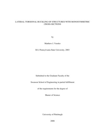
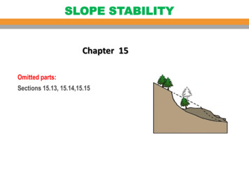
Module 9Stability and BucklingReadings: BC Ch 14Learning Objectives Understand the basic concept of structural instability and bifurcation of equilibrium. Derive the basic buckling load of beams subject to uniform compression and differentdisplacement boundary conditions. Understand under what conditions structural design is limited by buckling considerations. Understand the response of beam structures under a combination of tranverse loadsand intense compressive loads. Understand the postbuckling behavior of beam structures.9.1Introduction to bifurcation of equilibrium and structural instabilityConcept Question 9.1.1. Buckling of a rigid bar on a torsional springConsider a rigid bar with a torsional spring at one end and a compressive axial load atthe other end (Figure 9.1(a)). We consider the possibility that the bar can be in equilibriumnot just in the undeformed configuration θ 0, but perhaps in a deformed configuration aswell, Figure 9.1(b).1. State the equilibrium equation in the deformed configuration.Solution: To determine the critical value of P , we consider the equilibrium of themoment with respect to point O in Figure 9.1(b)P L sin(θ) Kθ θ209
210MODULE 9. STABILITY AND BUCKLINGPPL sin(θ)θLbcbcbcbcbcbcbcbcOKθ θO(b) θ 6 0(a) θ 0Figure 9.1: Equilibrium positions of a rigid bar on a torsional spring for a trivial solution(θ 0) and a non-trivial solution (θ 6 0).2. Rewrite the equations in the case of small anglesSolution: For small angles, sin(θ) ' θ, hence:(P L Kθ )θ 03. Interpret this equation. Under what conditions is it satisfied?equation can be satisfied in any of the two scenarios:Solution: This(a) θ 0. This is the trivial solution.(b) the parenthesis is zero, which required P Pcr KθL4. If the first solution is satisfied θ 0, what are the restrictions on the load P ?Solution: There are no restrictions, P can adopt any value (of course we are ignoringplastic yield or other material failure modes under compression, but for the purpose ofthis exercise we assumed the bar to be rigid).5. If the second solution is satisfied P Pcr , what are the restrictions on the angle ofrotation θ?Solution: There are no restrictions, θ can adopt any value.6. What is the implication?Solution: The implication is that once theload reaches the critical value, the rotation is unbounded (unstable). Increases in therotation angle leads to growth of the loading moment which is equal to the growth ofthe internal resisting moment. Then, any angle θ is an equilibrium position.7. Challenge: what happens for large angles?Solution:The loading moment P L sin θ grows slower than the resisting moment Kθ θ and in thelarge deformation case a second (stable) equilibrium configuration is obtained
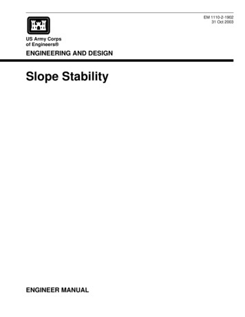
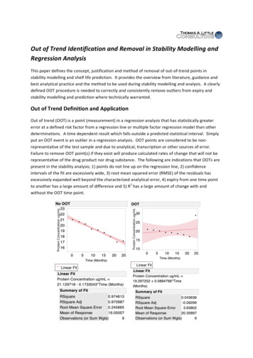
9.1. INTRODUCTION TO BIFURCATION OF EQUILIBRIUM AND STRUCTURAL INSTABILITY211Concept Question 9.1.2. Euler buckling load for a cantilever beame3Pū3 (x1 )δe1LFigure 9.2: Bifurcation of equilibrium in a compressed cantilever beamConsider a cantilever beam of length L made of a material with Young’s modulus E andwhose uniform cross section has a moment of inertia with respect to the x2 axis I22 . Thebeam is subjected to a compressive load P , as shown in the figure.We seek to find conditions under which the beam will buckle, i.e. the beam can be inequilibrium under the load P in a configuration involving non-trivial (non-zero) lateral deflections v(x). To this end, we enforce equilibrium of the beam in the deformed configuration.1. At a position x1 along the axis, the deflection of the beam is u3 (x1 ) and the momentproduced by the force P with respect to that point on the beam in the deformedconfiguration is given by.Solution: M2 P δ u3 (x1 )(9.1)where δ is the deflection at the cantilever’s tip:δ u3 (L)(9.2)and is an unknown of the problem2. Write the expression for the internal moment produced by the ensuing bending stressesin terms of the curvature at that pointSolution: From Euler-Bernoulli beam theory, the internal moment produced bythe ensuing bending stresses are given by:M2 EI22 u003 (x1 )(9.3)
212MODULE 9. STABILITY AND BUCKLING3. Show that enforcing equilibrium of internal and external moments leads to an ODE ofthe type:u003 (x1 ) k 2 u3 (x1 ) k 2 δand find kSolution: Setting Mint Mext , we obtain: EI22 u003 (x1 ) P δ u3 (x1 )dividing by EI22 and rearranging we obtain the sought expression with:k2 PEI22(9.4)4. The general solution of this ODE is:u3 (x1 ) A sin (kx1 ) B cos (kx1 ) δApply the appropriate boundary conditions to this problem to obtain the solution forthe deflection in terms of δ Solution: Applying the boundary condition u03 0 atx1 0, we find:kA cos (k0) B sin (k0) kA 0(9.5)from which we conclude that A 0. From the boundary condition u3 0 at x1 0,we obtain:B cos (k0) δ 0(9.6)which gives the value of B in terms of δ:B δ(9.7)u3 (x) δ(1 cos (kx1 ))(9.8)The solution is finally:which is given in terms of the unknown value of the deflection at the tip δ.5. From the solution obtained, use the condition that u3 (L) δ and derive two possiblesolutions to this problem: 1) the trivial solution where there is no deformation, 2) a nontrivial solution where equilibrium can occur in the deformed configuration providingthat the load is large enough.Solution: 1) this case is simply 0 δ, u3 (x1 ) δ(1 cos (kx1 ) 0 everywhere.In this case, k and therefore the load can adopt any value.2) 0 6 δ u3 (L) δ(1 cos (kL), which requires:cos (kL) 0(9.9)This condition is satisfied when the argument of the cosine is an odd multiple of π2 :kL (2n 1)π2(9.10)
9.1. INTRODUCTION TO BIFURCATION OF EQUILIBRIUM AND STRUCTURAL INSTABILITY2136. Express the non-trivial condition in terms of the applied load to obtain the criticalSolution: Replacing the value of k from equation ? we obtain:loadsrPπL (2n 1)EI222(9.11)from where we finally obtain the critical loads:Pcrn (2n 1)2π 2 EI224L2(9.12)7. What is the minimum value of the load P for which a non-trivial solution is found?Solution: The minumum value of this expression is attained for n 0 with theresult:π 2 EI22Pcr0 (9.13)4L2which is known as Euler’s buckling load.8. Find the mode shapes of the deformed cantilever for each value of the critical loadSolution: From the solution given by equation ? we obtain the correspondingbuckling modes:nhπ x1 ioun3 (x1 ) δ 1 cos (2n 1)(9.14)2L9. Sketch the first three buckling modes of the beam(a) First buckling mode, n 0(b) Second buckling mode, n 1Solution: Shown in Figure ?(c) Third buckling mode, n 2Figure 9.3: Buckling modes of a cantilever beam
214MODULE 9. STABILITY AND BUCKLINGp2e2Pp1ū2e1lFigure 9.4: Deformed beam with lateral and axial loads9.2Equilibrium equationsAs discussed in previous sections, they key ingredient in the analysis of bifurcation of equilibrium is to allow for the possibility that the structure will have additional equilibriumconfigurations in the deformed state. In order to express this in mathematical terms, weneed to restate the differential equations of equilibrium of the beam in the deformed configuration, Figure 9.3. Consider the equilibrium of an infinitesimal slice of beam of size dx1 ,Figure 9.4. Since we are interested in computing the critical buckling load, we will considerthe beam to be at the onset of buckling. Accordingly, we will assume that the deflection isvery small (ū02 1) and that the transverse shear force V2 is very small compared to thenormal force N1 (V2 N1 ).Force equilibrium in the e1 direction gives: N1 cos(ū02 ) (N1 N10 dx1 ) cos(ū02 ū002 dx1 ) V2 sin(ū02 ) (V2 V20 dx1 ) sin(ū02 ū002 dx1 ) p1 dx1 0According to the assumption of small deflection, it follows thatcos(ū02 ) 1 and cos(ū02 ū002 dx1 ) 1sin(ū02 ) ū02 and sin(ū02 ū002 dx1 ) ū02and we obtain:N10 V20 ū02 p10(N1 V2 ū02 ) V2 ū002 p1The term in ū002 is a second order differential term which can be neglected. The term V2 ū02 isvery small compared to N1 because ū02 1 and V2 N1 ; it is thus neglected as well. Theprevious equation can thus be re-written as follows:N10 p1where p1 is the distributed force in the e1 -direction.(9.15)
9.3. GOVERNING EQUATION215N1 N1′ dx1M3 M3′ dx1ū′2 ū′′2 dx1AM3bV2 V2′ dx1π ū′2V2N1dx1Figure 9.5: Free body diagram of an infinitesimal slice of the deformed beamForce equilibrium in the e2 direction gives: V2 cos(ū02 ) (V2 V20 dx1 ) cos(ū02 ū002 dx1 ) N1 sin(ū02 ) (N1 N10 dx1 ) sin(ū02 ū002 dx1 ) p2 dx1 0Using the same simplifications of the sines and cosines introduced above, the equation becomes:V20 N10 ū02 p20(V2 N1 ū02 ) N1 ū002 p2The term in ū002 is of second differential order and is thus neglected. However, both V2 andN1 ū02 are of the same order of magnitude. p2 is the distributed force in the direction e2 . Wethen obtain:0(9.16)V20 (N1 ū02 ) p2Moment equilibrium in the e3 direction with respect to point A shown in Figure 9.4 gives: M3 (M3 M30 dx1 ) V2 cos(ū002 dx1 )dx1 N1 sin(ū002 dx1 )dx1 0After applying the previously introduced sines and cosines simplifications and neglectinghigher order terms, the equation becomes:M30 V2 09.3(9.17)Governing equationThe general beam-column equation can be derived by differentiating (9.3) with respect tox1 and using the expression of V20 from (9.2):0(M30 V2 ) M300 V20 M300 (N1 ū02 )0 p2 0
216MODULE 9. STABILITY AND BUCKLINGThen, using the moment-curvature relationship (7.13), we arrive at:M300 (N1 ū02 )0 p2c 00 00(H33ū2 ) (N1 ū02 )0 p2(IV )cH33ū2 (N1 ū02 )0 p2cFinally in the case of homogeneous cross sections, we have H33 EI33 and the beam columnequation becomes:(IV )EI33 ū2 (N1 ū02 )0 p2(9.18)which is a fourth-order differential equation, that depends on N1 . Hence, in order to solve(9.4), one needs to solve first (9.1) with the appropriate boundary condition: N1 (L) P.In the case of no axial distributed force, (9.4) becomes:(IV )EI33 ū2 Pū002 p2(9.19)Solutions of (9.5) are of the form:rrPPū2 (x1 ) A sin(x1 ) B cos(x1 ) Cx1 DEI33EI33In order to solve this fourth-order differential equation we need four boundary conditions,two at each end.9.4Buckling loads and shapes for different beam boundary conditionsConcept Question 9.4.1. Buckling of a uniform beam simply supported at both endsConsider the case of a uniform beam (i.e, the product EI is constant along the beam) oflength L as shown in Figure 9.4.1. The beam is simply supported at both ends and loaded bya uniform axial force P which acts on the beam neutral axis. The displacement ū22 satisfiesthe governing equation (9.4) and the solution is given by (9.3).e2PbbLPe1Figure 9.6: Simply supported uniform beam at both ends.1. Write the boundary conditions needed to determine the constants A, B, C and D inthe solution of equation (9.3).Solution:
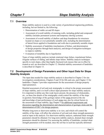
9.4. BUCKLING LOADS AND SHAPES FOR DIFFERENT BEAM BOUNDARY CONDITIONS217at x1 0 and x1 L: u2 (x1 0) 0M3 EI33 u002 (x1 0) 0and u2 (x1 L) 0M3 EI33 u002 (x1 L) 02. Using these boundary conditions, compute the three constants B, C and D to obtainthe non-trivial solution ū2 as a function of the constant A.Solution:for ū2 (x1 0) 0:rrPPū2 (x1 0) A sin( 0) B cos( 0) C 0 DEI33EI33 B D 0for M3 (x1 0) 0:rū002 (x1 0) P A sin( B 0rPP 0) P B cos( 0)EI33EI33hence, D 0.for ū2 (x1 L) 0:rū2 (x1 L) A sin(P L) C L 0EI33for M3 (x1 L) 0:ū002 (x1r L) AP sin(P L) 0EI33The last two equations can be satisfied under the following two conditions: 1) C A 0 u2 (x1 ) 0 x1 (trivial solution), in whichq case there is no restriction on theload P , 2) C 0, A 6 0, which will require sin( EIP33 L) 0. The deflection of thebeam is then given as a function of the undetermined constant A:rū2 (x1 ) A sin(P x1 )EI333. Using the boundary condition ū2 (x1 L) 0, determine the condition on the load Pfor which we have a non-trivial solution for ū2 (i.e ū2 6 0).
218MODULE 9. STABILITY AND BUCKLINGSolution: As we saw, the non-trivial solution requiressinrPL 0, EI33rPL nπEI33The buckling loads are then given by:Pcrn n2 π 2 EI33L2which is similar to the equation (?).And the corresponding buckling deflection modes byū2 (x1 ) A sin(nπx1)L4. Determine the lowest (Euler) buckling load Pcrn 1:π 2 EI33Pcr1 L2Solution: This is obtained for(9.20)5. Compare the Euler buckling load for a simply supported beam with the one obtainedpreviously for a cantilever beam (equation (?)).Solution: In the case of acantilever beam, we found:π 2 EI22Pcr0 4L2By comparing the two equations we see that the Euler buckling load for a simplysupported beam is 4 times higher than that for a cantilever beam.Concept Question 9.4.2. Buckling of a uniform beam clamped at both endsConsider the case of a uniform beam of length L as shown in Figure 9.4.2. The beam isclamped at both ends and loaded by a uniform axial force P at (x1 L) which acts onthe beam neutral axis. The displacement ū22 satisfies the governing equation (9.4) and thesolution is given by (9.3).1. Write the boundary conditions needed to determine the constants A, B, C and D inthe solution:rrPPū2 (x1 ) A sin(x1 ) B cos(x1 ) Cx1 DEI33EI33
9.4. BUCKLING LOADS AND SHAPES FOR DIFFERENT BEAM BOUNDARY CONDITIONS21910.80.60.4ū2 /A0.20 0.2 0.4 0.6k π/Lk 2π/L 0.8 100.10.20.30.40.5x1 /L0.60.70.80.91Figure 9.7: Deformation modes of the simple supported beam.
220MODULE 9. STABILITY AND BUCKLINGe2Pe1LFigure 9.8: Uniform beam clamped at both ends.Solution:at x1 0 and x1 L: u2 (x1 0) 0u02 (x1 0) 0and u2 (x1 L) 0u02 (x1 L) 0(9.21)2. Using these boundary conditions, determine the condition on the load P for which thebeam can be in equilibrium in a deformed configuration, (i.e. we have a non-trivialsolution ū2 6 0).Solution:for ū2 (x1 0) 0:rrPPū2 (x1 0) A sin( 0) B cos( 0) C 0 DEI33EI33 B D 0for ū02 (x1 0) 0:rrrrPPPPū02 (x1 0) A cos( 0) B sin( 0) CEIEI33EI33EI33r 33P A C 0EI33for ū2 (x1 L) 0:rū2 (x1 L) A sin(rPP L) B cos( L) C L DEI33EI33for ū02 (x1 L) 0:ū02 (x1 L) rrrrPPPPA cos( L) B sin( L) CEI33EI33EI33EI33We obtain the following system:
9.4. BUCKLING LOADS AND SHAPES FOR DIFFERENT BEAM BOUNDARY CONDITIONS221 q010 1 P 01 0 EI330 0 qq 0 sin( EIP33 L)cos( EIP33 L)L 1 0 qqqqPPPPcos( L) sin( L)10EI33EI33EI33EI33ABCD For a non trivial solution: A B6 C D0000 which requires the matrix to beq singular, i.e. its determinant must vanish. Let’s callthis matrix H and define k EIP33 .k1 0k01sin(kL)L1sin(kL)cos(kL)Ldet(H) k cos(kL) 1 0k cos(kL) k sin(kL) 1 k1cos(kL)Lsin(kL)cos(kL) k k cos(kL) 1 k sin(kL) 1k cos(kL) k sin(kL) k(1 cos(kL)) k(cos(kL) Lk sin(kL)) k sin2 (kL) k cos2 (kL) k k cos(kL) k cos(kL) Lk 2 sin(kL) k 2k 2k cos(kL) Lk 2 sin(kL) kLsin(kL) 2k 1 cos(kL) 2 kLkLkL2 kL 2k 1 [1 2 sin ( )] 2 sin( ) cos( ))2222 kLkLkLkL 4k sin( ) sin( ) cos( )2222 0,which implies the three cases:(a) k 0(b) sin( kL) 0, or2k 2nπL(9.22)
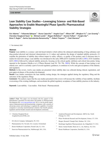
222MODULE 9. STABILITY AND BUCKLING(c) sin( kL) 2kL2cos( kL) 0, or2tan(kLkL) .22(9.23)In Case (?), we can replace k by its original expression and obtainrP2nπ EI33Lhence:Pcrn 4n2 π 2 EI33L2In this case, the displacement ū2 reads: 2nπx1 ) 1ū2 B (cos(kx1 ) 1) B cos(L In Case (?), the solution is also a series of numbers due to the periodicity of tangentialfunction. The solutions can be obtained numerically, and the first two are 8.97( 2.85π),LL15.454.92π( ),whichleadtoLLPcr k 2 EI33 80.76EI338.18π 2 EI33 238.72EI3324.19π 2 EI33( ),( ), .L2L2L2L2Set B 1 and then coefficients A, C, D can be determined by solving the reducedlinear system.The first two deformation modes from Case (?) and Case (?) are plotted in Figure9.4.2.3. Determine the Euler critical load Pcr0 and compare the expression obtained with thosefound for the simply-supported and the cantilever beam.Solution:Pcr0 4π 2 EI33L2we obtain:(Pcr0 )clamped 4 (Pcr0 )simply supported 4 (Pcr0 )cantilever
9.4. BUCKLING LOADS AND SHAPES FOR DIFFERENT BEAM BOUNDARY CONDITIONS2232k 2π/L1.5k 2.85π/Lk 4π/L1k 4.92π/Lū2 /B0.50 0.5 1 1.5 200.10.20.30.40.5x1 /L0.60.70.80.9Figure 9.9: Deformation modes of the clamped beam.1
224MODULE 9. STABILITY AND BUCKLINGe2aPbLe1Figure 9.10: Clamped beam at both ends with an intermediate support at x a.Concept Question 9.4.3. Buckling of a uniform beam clamped at both ends with an intermediate supportConsider the uniform beam of length L, clamped at both ends (Figure 9.8) loaded by a forceP at the right end (x1 L) along the beam neutral axis. An additional support is placedat the cross-section x1 a, as shown in the figure.1. The analysis is done considering the left and right regions as separate solutions andthen enforcing compatibility at the support. The transverse displacement is denotedū2 and ũ2 in the first and second region, respectively.Determine the general form of the transverse displacement ū2 and ũ2 in both regions.Solution: The differential equationsFor convenience, we introduce k 2 P/EI33 .governing the transverse displacement in both regions, 1 and 2 are the following:P 00ū 0 for 0 x1 aEI33 2P 00(IV )ũ2 ũ 0 for a x1 LEI33 2(IV )ū2 Thus, both, ū2 and ũ2 have the same following form:ū2 (x1 ) A1 sin(kx1 ) B1 cos(kx1 ) C1 x1 D1ũ2 (x1 ) A2 sin(kx1 ) B2 cos(kx1 ) C2 x1 D22. Determine the boundary conditions on the beam:conditions read for ū2 :Solution: The boundaryū02 (x1 0) 0 kA1 C1 0ū2 (x1 0) 0 B1 D1 0ū2 (x1 a) 0 A1 sin(ka) B1 cos(ka) C1 a D1 0and for ũ2 :ũ02 (x1 L) 0 kA2 cos(kL) kB2 sin(kL) C2 0ũ2 (x1 L) 0 A2 sin(kL) B2 cos(kL) C2 L D2 0ũ2 (x1 a) 0 A2 sin(ka) B2 cos(ka) C2 a D2 0
9.4. BUCKLING LOADS AND SHAPES FOR DIFFERENT BEAM BOUNDARY CONDITIONS2253. Are the previously found boundary conditions enough to compute the solution on bothsides of the additional support? If not, what other conditions must be satisfied by ū2Solution: At thisand ũ2 on both sides of the additional support?stage we are two equations short to fully compute the transverse displacement on bothside of the additional support. We are still missing continuity conditions of the slopeand the bending moments – We have already enforced continuity of displacements atthe intermediate support by applying the null displacement condition at x1 a in theprevious question. These continuity conditions read:ū02 (x1 a) ũ02 (x1 a)ū002 (x1 a) ũ002 (x1 a)(continuity of the slopes)(continuity of the bending moments)4. Apply the boundary conditions only and show that the displacements: ū2 and ũ2 canrespectively be written as:ū2 A ((cos(ka) 1)(sin(kx1 ) kx1 ) (sin(ka) ka)(cos(kx1 ) 1))ũ2 C ((cos(k(L a)) 1)(sin(k(L x1 )) k(L x1 )) (sin(k(L a)) k(L a))(cos(k(L x1 )) 1))Solution:Replacing Bi , Ci , Di by Ai , we can obtain: sin(ka) ka(cos(kx1 ) 1)ū2 A1 sin(kx1 ) kx1 cos(ka) 1 sin(k(L a)) k(L a)ũ2 A2 sin(k(L x1 )) k(L x1 ) (cos(k(L x1 )) 1)cos(k(L a)) 1Then we can define A A1 /(cos(ka) 1) and C A2 /(cos(k(L a)) 1) to simplifythe expression.5. Apply the additional conditions to both ū2 and ũ2 and derive a system of two equationsdepending on: A, C. What condition should satisfy the system of equation so thatnon-trivial solutions are found?Solution:Apply the two continuity conditions and use trigonometric idenities, we can obtain:A[2 2 cos(ka) ka sin(ka)] C[2 2 cos(kâ) kâ sin(kâ)] 0A[ sin(ka) ka cos(ka)] C[ sin(kâ) kâ cos kâ] 0where â L a. The non-trivial solution can be found when the determinant of the2-by-2 linear system is zero, i.e. when0 [2 2 cos(ka) ka sin(ka)] [sin(kâ) kâ cos kâ] [2 2 cos(kâ) kâ sin(kâ)] [sin(ka) ka cos(ka)]
226MODULE 9. STABILITY AND BUCKLING6. Let us introduce the following non-dimensional quantities u a/L and α kL, andrewrite the previously found condition.Solution: With definition u a/L,α kL, and the â L a we just defined above, we can get identities: ka αu andkâ α(1 u). The previous condition now can be written as0 [2 2 cos(αu) αu sin(αu)] [sin(α(1 u)) α(1 u) cos(α(1 u))] [2 2 cos(α(1 u)) α(1 u) sin(α(1 u))] [sin(αu) αu cos(αu)]7. Determine the location of the intermediate support (a a ) for which the bucklingload will attain a maximum, hence the best location of the intermediate support toavoid buckling.Solution:For a a , the buckling load will attain a maximum value and corresponds herein tou a /L. The previously found condition is an equation of α and u. In other word,α may be viewed as an implicit function of u. The previous equation can be writtenas follows using trigonometric identities:f (α(u), u) [2 2 cos(αu) αu sin(αu)] [sin(α(1 u)) α(1 u) cos(α(1 u))] [2 2 cos(α(1 u)) α(1 u) sin(α(1 u))] [sin(αu) αu cos(αu)] 2 α u(1 u) 2 sin(α) α cos(α) α cos(αu) cos(α(1 u)) 2 sin(α(1 u)) 2 sin(αu) 2α(1 u) cos(α(1 u)) 2αu cos(αu) 0 .Let’s derive the function f with respect to u: f dα f 0. α du uThus,dα du f α 1 f u ,assuming that f / α 6 0. The condition:dα 0,duis then equivalent to: f 0, uwhich leads to:(1 2u)α2 sin(α) α2 sin(α(1 2u)) 2α2 (1 u) sin(α(1 u)) 2α2 u sin(αu) 0 .
9.5. BUCKLING OF BEAMS WITH IMPERFECTIONS227We immediately identify that u 1/2 satisfies this equation, and therefore dα(u ) 0.du By substituting u u 1/2 into the previous equation f (α(u), u) 0, we can obtain:α 4π .In sum, the location of the intermediate support that maximizes the buckling load isin the middle of the beam. The buckling load is equal to:Pcr 9.516π 2 EI.L2Buckling of beams with imperfectionsSo far, we have assumed idealized beams with mathematically exact geometries, made ofperfectly homogeneous materials and loads perfectly aligned with the centroid axis. In reality, beams have imperfections due to the fabrication process and cannot be considered ashomogeneous or geometrically exact. In this section, we study the effect of these imperfections.Concept Question 9.5.1. Buckling of a simply supported beam with an imperfectionWe will account for any geometric imperfection in the material as an eccentricity in theapplication of the load. Consider a simply-supported beam of length L as shown in Figure9.5.1. The uniform compressive load applied at the free end has an eccentricity e.e2bbe1ePLFigure 9.11: Simply supported beam with eccentric end load1. what do you think is the main difference with the idealized buckling problem? Howdoes the influence of the eccentricity affect the analysis?Solution: The maindifference is that the load P now produces a bending moment even in the undeformedconfiguration. We will call this the primary bending moment. This is the moment thatwe would need to consider in the absence of structural instability considerations, i.e.in linear beam theory. The analysis changes in a fundamental way, as now the problemhas non-homogeneous boundary conditions.
228MODULE 9. STABILITY AND BUCKLING2. how do you think the governing equation changes with respect to the idealized bucklingSolution: It doesn’t change at all, the differential equation is still theproblem?homogeneous equation used in the idealized case, as there is no distributed transverseforce, i.e. p2 03. Write the boundary conditions needed to determine the constants A, B, C and D inthe solution:rrPPx1 ) B cos(x1 ) Cx1 Dū2 (x1 ) A sin(EI33EI33Solution:at x1 0 and x1 L: u2 (x1 0) 0M3 (x1 ) EI33 u002 (x1 0) P eand u2 (x1 L) 0M3 (x1 ) EI33 u002 (x1 L) P e4. Apply the boundary conditions and find the solution ū2 .Solution: for ū2 (x1 0) 0:rPP 0) B cos( 0) C 0 Dū2 (x1 0) A sin(EI33EI33 B D 0rfor M3 (x1 0) P e:ū002 (x1rP 0) P A sin( 0) P B cos(EI33 P B P e B erP 0)EI33hence D e.for ū2 (x1 L) 0:rū2 (x1 L) A sin(for M3 (x1 L) P e:rPP L) e cos( L) C L e 0EI33EI33rPM3 (x1 L) AP sin( L) eP cos(EI33q(1 cos( EIP33 L))q A esin( EIP33 L)rP L) P eEI33
9.5. BUCKLING OF BEAMS WITH IMPERFECTIONS229hence, C 0. we finally obtain the displacement ū2 as a function of e:q rr (1 cos( EIP L)) PP33qsin(ū2 (x1 ) ex1 ) cos(x1 ) 1 sin( EI33EI33P L)EI335. Notice that we did obtain a fully defined solution in this case. No bifurcation ofequilibrium in this case? How come? What happens to the solution as P approachesSolution: Wethe critical load?found a solution because this is a non-homogeneous problem, i.e. solving the governingequation responds to the question: how does the beam deform under the applicationof the load p0 (and how does the influece of P modify that response. This is a verydifferent question from: under what conditions (what values of P ) would this beam beable to be in equilibrium in the deformed configuration (in addition to the undeformedconfiguration)? So there is no bifurcation of equilibrium.It can be seen in the solution that when P approaches the critical load the displacementsgrow unboundedly, i.e., the beam would fail.6. Determine the relation P f (ū2 (L/2)) at the middle of the beam and plot this expression for different ratios e/LqSolution: Let’s use k EIP33 (1 cos(k L))LLsin(k ) cos(k ) 1sin(k L)22()L(1 cos(2k 2 ))LLesin(k ) cos(k ) 122sin(2k L2 )()(1 cos(2k L2 ))LLesin(k ) cos(k ) 1222 sin(k L2 ) cos(k L2 )()(1 cos(2k L2 ))Le cos(k ) 1L22 cos(k 2 )()2 sin2 (k L2 ))Le cos(k ) 122 cos(k L2 )()1e 1cos(k L2 ))Lū2 (x1 ) e2 and we have:4P EI33 2 arccos2LeLū2 ( 2 ) e!
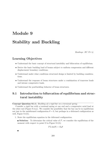
230MODULE 9. STABILITY AND BUCKLINGso4P 2 arccos2Pcrπwith Pcr eLū2 ( 2 ) e!π 2 EI33L27. Draw the function f for several values of the ratio e/L and interpret the result.Solution: For low values of the load P : 1) an increase of the load leads to anessentially linear growth of the deflection at the center, 2) increasing the eccentricitye increases the primary moment (for a fixed P ) and thus the deflection.As the load increases and becomes a significant fraction of the critical load, the behaviordeviates from the solution of linear elasticity and the secondary moment produced bythe load P with the extra moment arm corresponding to the deflection further increasesthe deflection. When the load gets close to the critical value, the deflections growunbounded.The plots also bears the interpretation that as the imperfections disappear there is asmooth transition to the solution of the bifurcation problem.1.21P/Pcr0.80.60.4e/L 0.01e/L 0.05e/L 0.1e/L 0.2e/L 0.5e/L 1.00.200246ū2 (L/2)/L810Figure 9.12: simply supported beam with eccentric end load8. Find the distribution of the bending momentSolution: It follows directly that:qrrh 1 cos EIP LiPP33qM3 EI33 u002 P esinx1 cosx1EI33EI33sin EIP33 L
9.6. OTHER ISSUES IN BUCKLING INSTABILITY9. Interpret the result in the limits P 0, Pcr231Solution:P 0, M3 P ei.e. the primary bending moment obtained when equilibrium in the undeformed configuration is consideredP Pcr ,PL π M3 EI33i.e. as the load reaches the critical load, the moment grows unbounded.9.6Other issues in buckling instabilityConcept Question 9.6.1. We saw that beams and columns under states of strong compression buckle.1. Is this always true? If not, what other considerations come into play and when wouldSolution: Buckling occurs if the compressive force approaches thethat happen?. If the beam is long, the critical load iscritical value which in all cases scales as π 2 EIL2low and the beam buckles under fairly low loads which implies that the stresses in thematerial are low as well (poor structural efficiency).For short beams, the critical load increases quadratically with the reduction in length,which means that the likelihood of buckling decreases, whereas the stress σ11 PA canincrease with P to high values and reach material limits.2. In order to start looking at this problem, let’s write the critical load for general boundary conditions as:EIEIEIPcr cπ 2 2 π 2 π 2 02LLL( )2c {z}L0where we define c as the coefficient of fixity which depends on the boundary condition(e.g. c 1 for simply supported, c 4 for clamped-clamped, c 1/4 for cantilever,etc). L0 Lc as the equivalent length for buckling.3. In order to compare the competition between buckling and material failure by compression, evaluate give an expression for the stress in the material when the load approachesthe critical valueSolution: This is simply: ρ 2PcrI2 Eσ11 π 02 π2EALAL0 {z }ρ2
232MODULE 9. STABILITY AND BUCKLINGwhere we have defined:ρ rIAas the radius of gyration. (Interpretation?)04. Define the beam slenderness ratio as λ Lρ and plot the “buckling stress” as afunction of λ. Superimpose in your plot the material limiting stress (yielding, crushing)and define regions of beam response as a function of the slenderness ratio (buckling,crushing or squashing and transition between the two.Solution:
212 MODULE 9. STABILITY AND BUCKLING 3.Show that enforcing equilibrium of internal and external moments leads to an ODE of the type: u 00 3 (x 1) k 2 u 3 (x 1) k 2 and nd k Solution: Setting M int M ext, we obtain: EI 22 u 00