Transcription
Leadership in Sustainable InfrastructureLeadership en Infrastructures DurablesVancouver, CanadaMay 31 – June 3, 2017/ Mai 31 – Juin 3, 2017LATERAL TORSIONAL BUCKLING ANALYSIS AND DESIGN OF STEELBEAMS WITH CONTINUOUS SPANSSahraei, Arash1, Pezeshky, Payam2 and Mohareb, Magdi3,41 Graduateresearch assistant, University of Ottawa, Canadaresearch assistant, University of Ottawa, Canada3 Professor, University of Ottawa, Canada4 MagdiEmile.Mohareb@uottawa.ca2 GraduateAbstract:Design standards do not provide provisions to account for the interaction between adjacent spans ofcontinuous beams. In the absence of such provisions, the designer may opt for calculating the lateraltorsional buckling capacity for each span separately by applying the moment gradient factors provided instandards and adopting the smallest critical moment as the one governing the design. The Salvadorihypothesis of isolating a member from the rest of the structure is assessed in the present study. The elasticlateral torsional buckling resistance for continuous beams is investigated based on finite element analysis.Comparisons are made between two types of solutions: (1) those neglecting interaction effects betweenadjacent spans, and (2) those considering span interaction. Also examined is the effect of presence oflateral/torsional restraints at intermediate supports of continuous beams. The results illustrate the merits ofadopting the FEA solution in accounting for span interaction when determining the elastic lateral torsionalbuckling capacity of continuous beams.Keywords: lateral torsional buckling, finite element analysis, interaction effects, moment gradient factors,continuous beams1. INTRODUCTION AND LITERATURE REVIEWPresent provisions in design standards (e.g., CAN/CSA-S16-14 (2014), EN 1993 Designer’s guide(Gardner and Nethercot 2011), AS-4100 (1998) and ANSI/AISC-360-16 (2016)) do not account for theinteraction between various segments of a continuous beam when determining their lateral torsionalbuckling (LTB) resistance. In the absence of such provisions, designers may resort to treating eachsegment as a separate span and calculate the individual LTB capacity for each segment separately byadopting moment gradient factors and critical moment equations provided in standards, and then,conservatively, adopt the smallest critical moment as the one governing the LTB capacity of the continuousbeam. The above procedure omits the interaction effect between adjacent members. Procedures thataccount for such interaction effects were proposed in the work of (Nethercot and Trahair 1976), (Trahair1977) and (Trahair and Bradford 1988) as reported in SSRC guide (Ziemian 2010). Such procedures areiterative and based on an analogy between the LTB buckling of continuous beams and flexural buckling ofcontinuous columns. According to (Ziemian 2010), in most cases, these procedures lead to conservativeestimates for the critical moments while in cases of high moment gradients, they can overestimate the LTBbuckling strength. The present study documents a LTB Finite Element Analysis (FEA) that capturesEMM635-1
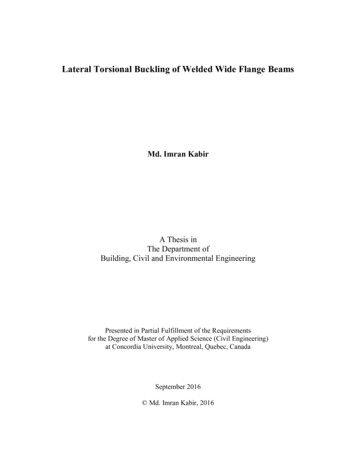
interaction effects in continuous beams. To establish the validity of the FEA model, the FEA is first adoptedto determine the critical moments for a number of single span problems under a variety of loads andcomparisons are made against the critical moment predicted by design standard provisions. The finiteelement is then adopted to investigate the span interaction effect on the lateral torsional buckling ofcontinuous beams and identify conditions where interaction effects are significant. The model is then usedto quantify the effect of lateral and torsional restraints that may be present at intermediate supports.2. OVERVIEW OF FINITE ELEMENT FORMULATIONThe formulation is based on the following assumptions:1. Material is linearly elastic, isotropic and homogenous.2. The beam follows the Vlasov beam kinematics (Vlasov 1961), i.e., the section is assumed to movein its own plane as a rigid disk and the shear strain in the middle surface of the beam is negligible.3. Pre-buckling deformations and local warping effects are neglected.The beam finite element in (Barsoum and Gallagher 1970) is chosen to conduct the study. The elementhas two nodes, each having three pre-buckling and four buckling degrees of freedom (DOF) as shown inFigure 1a. The pre-buckling DOFs are the longitudinal displacement u , the transverse displacement wand the strong-axis rotation w and the buckling displacements are the lateral displacement v , the weakaxis rotation v , the angle of twist x and warping deformation x . In Figure 1a, displacements are shownwith red single arrows, rotations are depicted with blue double-headed arrows while the warpingdisplacements are illustrated by green triple-headed arrows.(a)(b)Figure 1: (a) Buckling DOFs and adopted right-handed coordinate system, and (b) Internal forceinterpolation bending momentThe strong-axis bending moments M y 1 and M y 2 at the ends of each member are obtained from the prebuckling analysis. Assuming the beam element length L is small, the bending moments within the elementare linearly interpolated (Figure 1b), i.e., My x My 1 1 x L My 2 x L . The total potential energy ingoing from the point of onset of buckling to the buckled configuration is expressed in terms of bucklingdisplacements as[1] eb Ub Vb Uv Usv Uw Vm VPL VqL where the internal strain energy U b is the sum of three components; Uv due to the lateral displacement v, Usv due to the conventional Saint-Venant torsion, and Uw due to warping torsion. Also, the destabilizingload potential energy term Vb consists of three components; Vm due to the bending moments, VPL due tothe load height above the shear centre for point loads, and VqL is load height effect above the shear centrefor line loads. By expressing the above six terms in terms of the lateral displacement v and the angle oftwist θ x , one obtains635-2
LLLnp 1L L 11112[2] eb EIz v dx GJ x 2dx ECw x 2dx My x xv dx Pi zi xi2 q x zq x2dx 202020i 1 2 20 0 where G is the shear modulus, J is the Saint-Venant torsional constant, I z is weak-axis moment of inertia,Cw is the warping constant, zi is the vertical distance between the section shear centre and the point ofapplication of transverse load Pi i 1,., np taken as positive in the positive direction of coordinate z ,q x is the member transverse line load, and zq is the vertical distance between the shear centre and theline of application for q x , taken positive in the positive direction of coordinate z . The lateral displacementv x and angle of twist x x are related to the nodal displacements using Hermitian polynomials. Bysubstituting into Eq. [2] and evoking the stationarity conditions, one obtains the linearized eigenvalueproblem:[3] K K U 0 Gwhere K is the elastic stiffness matrix, K G is the geometric stiffness matrix, the eigenvalue λ is a loadmultiplier that determines the buckling load(s) at the which the system buckles and the eigen vector U is the buckling configuration.3. VALIDATION STUDYThree beam geometries were considered to assess the validity of the FEA. These are: 1) a W410x39 witha 4.5m span, 2) a W410x39 with an 8m span, and 3) a W310x52 with a 5.7m span. All beams were simplysupported with respect to the lateral displacement and twist (i.e., v 0 v L x 0 x L 0 , but freeto undergo weak-axis rotation and warping, i.e., v 0 0,v L 0, x 0 0, x L 0 as may be thecase in beams connected to columns through simple shear connections. A variety of loading conditionswere investigated; end moments M, M , where 1,0.75,0.5,0.25,0, 0.25, 0.5, 0.75, 1 (runs #1-9),uniformly distributed loads with and without fixed end moments (runs #10, 11), mid-span point load withand without fixed end moments (runs #12, 13), and two point loads acting at third spans (run #14). A meshstudy indicated that eight finite elements are needed to achieve convergence. Thus, eight elements wereused to mesh all beams. In each case, the critical moments Mcr Mcr FEA based on FEA were computedand the corresponding moment gradient C C FEA was determined from the equation[4] Mcr CMu C LEI y GJ E L Cw I y2where Mu L EI y GJ E L Cw I y is the critical moment for the idealized case of a simply supported2beam v 0 0 v L L 0 xxsubjected to uniform moments. The corresponding momentgradient values are provided in Column 2 of Table 1. The critical moment expression in Equation [4] isuniversal in most standards. For example, the Eurocode guide adopts equation [4] in conjunction withmoment gradient factors C C EUR prescribed for various loading conditions as provided in Column 3of Table 1. Also, the Canadian standards CAN/CSA-S16-14 adopt equation [4] with a moment gradientfactor C C CAN 2 given by635-3
[5] C CAN 4Mmax 2Mmax 4Ma2 7Mb2 4Mc2 2.5where Ma , Mb , Mc are moments are the quarter, mid-span, and three-quarter span points, and Mmax is thepeak moment within the span. The corresponding values are provided in Column (5) of Table 1. The ratiosC EUR C FEA of the moment gradient factors of the Eurocode guide to those predicted by the FEA areprovided in Column (4) and show close agreement except for run #11 and to a lesser degree for run #13,both involving fixed end moments. A comparison for C CAN C FEA is provided in Column (6). Themean value of C CAN C FEA is 0.936 with a standard deviation 0.0703. In all cases, except run #14,the Canadian moment gradient equation tends to under-predict the critical moments compared to the FEAresults.Run#(1)Table 1: Comparison of MFG of FEA, CAN/CSA-S16-14 and EN 1993C FEA C EUR BendingAverageC EUR C CAN /Momentvalue ofC FEA (3)(5)PatternFEA(4)(2)C CAN /C FEA andard Deviation4. CASE STUDY 1: DEVELOPING DESIGN AIDS FOR CONTINUOUS BEAMSConsider four continuous beams with equal spans where the spans L vary in the range L 4,5,6,7,8m rtiesIyy 1.88 10 5 m4 , J 4.09 10 7 m4 ,Cw 2.68 10 7 m6 . All supports provide lateral and torsional 635-4
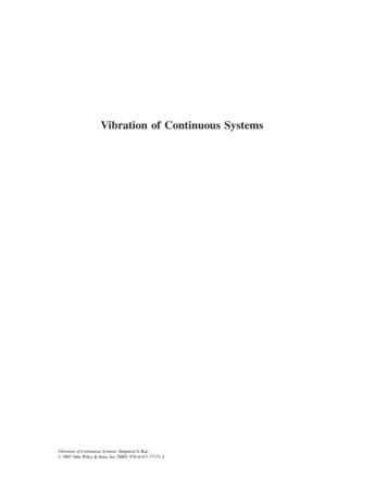
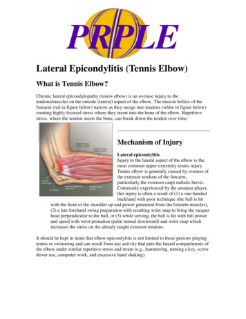
restraints (as marked by the red X) in addition to a transverse restraint. Case (a) involves two spans and issubjected to mid-span point loads P (Figure 2a). Case (b) involves two spans and is subjected to auniformly distributed load (UDL) (Figure 2b). Case (c) involves three spans and is subjected to mid-spanpoint loads P (Figure 2c) and Case (d) involves three spans and is subjected to UDL (Figure 2d). Thepertinent bending moment diagrams (BMD) are shown below each Case. All loads are applied at the shearcentre. It is required to determine the critical moment in each case, and use the results to develop designaids by developing moment gradient factors or effective length factors. In a manner similar to the validationstudy, the moment gradient factor C FEA is obtained from the FEA predicted critical moment Mcr FEA 2through the relation C FEA Mcr FEA L EI y GJ E L Cw I y . Alternatively, one can obtain the effective length factor by solving the equation Mcr FEA kL EI y GJ E kL Cw I y for k . Figure 3a2depicts the relationship between the moment gradient factor C FEA and the torsion parameter L GJ ECw and Figure 3b depicts the relationship of the effective length factor k versus the torsionparameter . The results show that the moment gradient factors are nearly constant, suggesting theindependence of moment gradient of the torsion parameter. In contrast, the effective length factors show amild dependence on the section torsional parameter. This observation suggests that the moment gradientfactor provides a simpler approach to estimate the critical moments than effective length approach. Thevalues provided in Table 2 show that the moment gradient factors is constant for Case (a). Thus a value ofC 1.82 is recommended for Case (a). In a similar manner, the recommended moment gradient factor is2.29 for Case (b). Cases (c) and (d) show a rather weak dependence on the torsion parameter, and thesmallest values of 1.65 are recommended for Case (c) and 1.75 for Case (d). For run #11 involving threespans with L 4m, the critical moment based on the Canadian Standard equation is 515.3 kNm for theexterior span and 736.3 kNm for the intermediate span. Since there is no direct means of accounting forspan interaction in the standards, the critical moment is conservatively taken as the smaller value of 515.3kNm. This value compares to 891.4 kNm based on FEA. As expected, the FEA solution predicts a highercritical moment since (a) it accounts for interaction effects whereby the stronger span delays the bucklingof the weaker span, and (b) the moment gradient equation in the standard is only approximate. For Run #1involving two- spans with L 4m, the critical moment for both spans predicted by the Canadian Standardequation is 515.2 kNm. An identical value is obtained by modeling a single span, suggesting no interactioneffects between identical spans under identical loads. This value compares to 704.9 kNm as predicted bythe present FEA solution, suggesting that for the present loads, the CAN-CSA-S16-14 moment gradientequation provides an overly conservative critical moment prediction.(a)(c)635-5
(b)(d)Figure 2: Continuous beams of Example 1: (a) Two-span beams under mid-span point loads, (b) Twospan beams under UDL, (c) three-span beam under mid-span point loads, and (d) three-span beamunder UDLEffective LengthFactor kMoment GradientFactor C(FEA)2.521.512-span under UDL2-span under point load3-span under UDL3-span under point load0.50246Torsional Parameter χ(a)0.80.70.60.50.40.30.20.102846Torsional Parameter χ8(b)Figure 3: (a) Moment gradient factor vs , and (b) Effective length factor vs Run #5 is chosen to illustrate the remaining steps of the design. Given that the W250x58 cross-sectionmeets class 2 requirements for a yield strength Fy 350MPa , the plastic moment is calculated asMp Zx Fy 270kNm . For run #5, the critical moment is Mu 275.6kNm (Table 2). Given thatMu 0.67M p , the design is governed by inelastic lateral torsional buckling and the resistance is given byMr Mp 1 0.28 Mp Mu 174.8kNm Mp . If one assumes the service dead load PD is equal to theservice live load PL , one has P 1.25PD 1.5PL 2.75PL or PL 0.364P . The peak factored momentcorresponding to Pas provided in Figure 2a is Mf 0.188PL . Equating the resisting momentMr 174.8kNm to the factored moment Mf 0.188PL yields a factored load P 116kN whichcorresponds to a service live load PL 0.364P 42.2kN . The corresponding peak displacement within thespan is found as 11.3mm which corresponds to L / 708 which is lower than the threshold value ofL / 360 given in appendix D of CAN-CSA-S16-14, i.e., the live load deflection meets the requirementof Appendix D.635-6
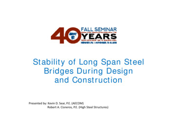
Table 2: Summarized results of Example 1CaseRun #Span (m) .8314.5264.9C FEA 00.5380.6900.6780.6670.6570.6505. CASE STUDY 2: INTERACTION EFFECTS IN CONTINUOUS BEAMS WITH UNEQUAL SPANSConsider a continuous beam with a W250x58 cross-section subjected to loads P1, P2 , P3 as shown inFigure 4a. The beam is laterally and torsionally restrained at the three support locations. It is required todetermine the elastic LTB capacity of the beam. Two types of solutions are sought: (1) Neglectinginteraction effects between both spans and (2) Considering interaction effects.(a)(b)Figure 4: (a) Continuous beam restrained laterally and torsionally at all three supports, and (b) BMDunder applied loadsSolution (1) - Omitting interaction: Since CAN/CSA-S16-14 does not account for the interaction betweenboth spans, the designer may opt to calculate the LTB capacity of each span separately by applying the635-7
moment gradient factors based on the quarter-point formula (Eq. 5). The procedure involves the followingsteps: Step 1: Determine the bending moment distribution (Figure 4Figure 4b), Step 2: Determine the criticalmoment for each span using the critical moment M cr expressions in Equation 4, where L is the distancebetween lateral torsional supports (i.e., the left span has L 4m and the right span has L 8m ). Step 3:Determine the critical moments for both spans by applying the quarter-point moment gradient equation (Eq.5) and conservatively taking the smaller value (i.e., neglecting the interaction between both spans). Table3 provides a summary of the results. For comparison, FEA predictions are provided for the case where theinteraction between both spans is omitted, by modelling each span alone in a separate buckling FEA modelwhile using 8 elements for each span.Solution (2) - Incorporating interaction effects: The FEA solution provides a natural means of incorporatingthe interaction between the two spans. This is done by modelling both spans in a single model. For thepresent problem, this interaction is beneficial for the weaker right span (which governs the design in Solution1). The stronger left span provides some restraint to left span and delays its buckling. By incorporatinginteraction effects and using 8 elements for each span, the critical moment of the system is found toincrease by 28.6% from the Canadian standards predictions (Table 3). As expected, the artificial isolationof each member leads to overly conservative predictions of the critical moments.Table 3: Comparison of critical moment predictions for a continuous beamEstimatedcriticalmoment forthestructureLeft SpanRight SpanSpan L m 4m8mMu Eq.4 386.9 kNm151.8 kNmM A kNm 5 5MB kNm 10 10MC kNm -5 15Mmax kNm -20-20C CAN Eq.5 2.2191.746858.5265.0265.01134295.1295.1Bending MomentDiagramsMcr CAN C CAN Mu kNm Mcr FEA 1 kNm-neglecting interaction(treating each span in aseparate model)M FEA 2 kNm accounting for interaction(treating both spans in asingle model)340.7 kNm635-8340.7
6. CASE STUDY 3: EFFECT OF LATERAL AND TORSIONAL RESTRAINTS AT INTERMEDIATESUPPORTSIn the previous case study, the middle support was assumed to be laterally and torsionally restrained. Inthe present example, it is required to investigate the case where intermediate support provides verticaldisplacement restraint but no lateral nor torsional restraints (Figure 5) as may be the case for a beamsupported by a column that is pinned at the base with no lateral members framing into the beam at thebeam to column junction. All other loading and end boundary conditions remain unchanged. Since theboundary conditions regarding the transverse displacements are identical to the past case study, the BMDremains identical (Figure 4b). However, in the absence of lateral and torsional restraints at the middlesupport, the unsupported span of the beam becomes 12m and quarter point moments becomeMA 5kNm, MB 5kNm, MC 12.5kNm and Mmax 20kNm . The critical moment calculations basedon the Canadian standard equation is found to be 211. 2kNm and the steps of the calculation are providedin Table 4. Also, provided for comparison are the critical moments predicted by the FEA which is 191.0kNm. The Canadian moment gradient equation is found to overestimate the critical moment by 10.5% inthis case. A comparison with the previous case study indicates that, although the bending momentdistribution remains identical in the two problems, the critical moment is found to drop from Mcr 340.7kNmfor the case where lateral and torsional supports are provided at mid-span to Mcr 191.0kNm for the casewhere such restraints are removed.Figure 5: Lateral torsional restraints removed at middle support (Example 3)Table 4: Critical moment comparisons for Example 3ResultsSpan L m 12m E Mu EIy GJ Cw IyL L M A kNm 295.20-5.0MB kNm 5.0MC kNm 12.5Mmax kNm -20C CAN Eq.5 2.219Mcr CAN C CAN Mu kNm 211.2Finite Element solution M FEA 191.0635-9
7. CONCLUSIONSThe following conclusions have been drawn from the current study:1. The present study implemented and established the validity of the beam finite element of Barsoumand Gallagher (1970) as part of a larger project to integrate the element within the commercial SFRAME analysis software and the S-STEEL steel design software.2. The formulation was successfully used to derive moment gradient factors in agreement with theEurocode Guide recommendations and CAN-CSA-S16-14 moment gradient factors. The elementwas then used to capture interaction effects between adjacent spans when calculating the LTBcapacity of continuous beams.3. Moment gradient factors were proposed for the design of two-span and three-span beams undereither mid-span point loads or UDL. The moment gradient factors account for span interaction.4. The study has quantified the effect of span interaction when determining the elastic LTB resistance.Span interaction was shown to play an important role for three-span beams and two-span beamswith unequal spans. In the majority of the cases considered, neglect of interaction effect by adoptingthe moment gradient factor in the CAN-CSA-S16-14 was shown to lead to conservative predictionsof the critical moments.5. The study quantified the effect of lateral and torsional restraints at intermediate supports. For Casestudies 2 and 3, removal of such restraints were shown to result in a significant drop in the criticalmoments.8. ACKNOLEDGEMENTSThe authors wish to express their gratitude to Mr. George Casoli, Dr. Feng Rong, Dr. Siriwut Sasibut, andDr. Marinos Stylianou, from S-FRAME Software Inc. for their instructive feedback and effort. Financialsupport from the S-FRAME Software Inc. and matching funds from the Natural Sciences and EngineeringResearch Council (NSERC) of Canada are also gratefully acknowledged.9. REFERENCESStandards Association of Australia (SAA). 1998, Steel Structures, AS4100-1998, SAA, Australian Instituteof Steel Construction, Sydney, Australia.CSA (2014). "Limit states design of steel structures." Standard CAN/CSA-S16-14, Canadian StandardsAssociation, Mississauga, Ontario.ANSI/AISC-360-16 (2016). "ANSI/AISC 360-16." Specification for structural steel buildings, AmericanInstitute of Steel Construction (AISC), Chicago, IL.Barsoum, R. S., and Gallagher, R. H. (1970). "Finite element analysis of torsional and torsional–flexuralstability problems." International Journal for Numerical Methods in Engineering, 2(3), 335-352.Gardner, L., and Nethercot, D. A. (2011). DESIGNERS’ GUIDE TO EUROCODE 3: (EN 1993-1-1, -1-3 and-1-8) DESIGN OF STEEL BUILDINGS, Imperial College London, UK.Nethercot, D. A., and Trahair, N. S. (1976). "Lateral Buckling Approximations for Elastic Beams." StructuralEngineering, 54(6), 197-204.Trahair, N. S. (1977). "“Lateral Buckling of Beams and Beam-Columns,’’ in Theory of Beam-Columns."McGraw-Hill, New York.Trahair, N. S., and Bradford, M. A. (1988). The Behaviour and Design of Steel Structures, Chapman & Hall,London.Vlasov, V. Z. (1961). Thin-walled elastic beams, 2nd Edition, Israel Program for Scientific Translation,Jerusalem.Ziemian, R. D. (2010). Guide to stability design criteria for metal structures, John Wiley & Sons, New York.635-10
Present provisions in design standards (e.g., CAN/CSA-S16-14 (2014), EN 1993 Designer’s guide (Gardner and Nethercot 2011), AS-4100 (1998) and ANSI/AISC-360-16 (2016)) do not account for the interaction between various segments of a continuous beam when deter