Transcription
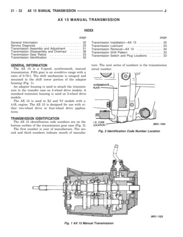
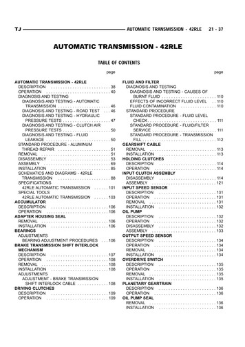
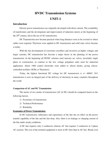
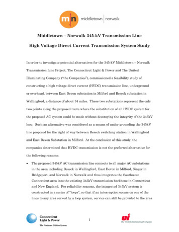
IJSRD - International Journal for Scientific Research & Development Vol. 6, Issue 06, 2018 ISSN (online): 2321-0613Analysis & Design of Transmission Tower & Monopole by using ManualCalculation & SoftwareMiss. Pooja D. Vaidya1 Prof. Riyaz Sameer Shah21PG Student 2Assistant Professor1,2Department of Civil Engineering1,2Prof Ram Meghe Institute of Technology & Research, Badnera, Amravati-444701,Maharashtra, IndiaAbstract— This research work is focused on comparison oftransmission tower and monopole tower for differentparameters viz. different height and different loadingcombinations. The comparative analysis is carried out withrespect to axial force deflection maximum sectional propertyand critical load conditions. The transmission tower andmonopole are design by manually by using limit state methodbased on IS 800, IS 802 IS 875 and gust factor method. Basedon steps and formulas involved, a design program will beprepare in MS-EXCEL. The veracity of program will becheck by first designing the manually designed transmissiontower and monopole using the software and compare results.Wind analysis is carried out using standard codes andsoftware. The behaviour of tower and pole is analysed fordifferent load combination. The maximum displacementvalues, shear forces and bending moments are obtained.Therefore, transmission tower and monopole should bedesigned considering both structural and electricalrequirements for safe and economical design as per Indiancode. It is concluded from past study that transmission towerhave lower lateral displacement as compared to monopole.This is because they have higher stiffness. Transmissiontower carry heavy electrical transmission conductor atsufficient and safe from the ground than monopole. Loadsacting on the tower and monopole are wind load, dead loadof the structure, braking load of conductor and earthquakeload considered as per Indian standard code. The steelquantity required for transmission tower is approximated twotimes more than monopole. The idea is to reach a definiteconclusion regarding the superiority of two structures.Key words: Transmission Tower, Monopole, Bracing, Loadscalculations include applied loads like wind load, dead load,seismic load and design strength of structural steel memberon superstructure including connection and foundation. Fromsafety considerations, along the route of the transmission lineclearances above open countries, roads, rivers, railway tracks,tele-communication lines, other power lines, etc. up toconductor needs to be maintained. The basic function of thetower is to isolate the conductors from their surroundings,including other conductors and the tower structure. . Analternative to the transmission tower, the monopole tower, isalso used in this power corridor. In this case, the monopolesupports much lower voltage conductors for distribution toindustrial customers and substations. The voltages requiredfor economical transmission of electric power exceeds thevoltages appropriate for distribution to customers.I. INTRODUCTIONIn last several studies have been performed in the area ofanalysis and design of metallic towers. The electrictransmission is the process by which large amounts ofelectricity produced at power plants is transported over longdistances for use by consumers. Usually steel transmissiontowers and monopoles are used to transmit the electric power.This is in view of non-availability of adequate land forinstallation of conventional lattice type tower. To overcomethese practical difficulties, a new concept of transmission lineis being used world-wide, called monopole. The cost oftransmission tower constitutes about quarter to half of the costof transmission line and hence optimum tower design willbring in substantial savings. The transmission tower aredesigned and constructed in wide variety of shapes, types,sizes, configuration and material. The supporting structuretype used in transmission line generally fall into one of thethree categories: lattice, pole guyed. According to IS 800-07,the wind forces are much prominent on the tower, conductorsand insulators, besides the self-weight. Tower structuralFig. 1: Transmission TowerFig. 2: MonopoleAll rights reserved by www.ijsrd.com100
Analysis & Design of Transmission Tower & Monopole by using Manual Calculation & Software(IJSRD/Vol. 6/Issue 06/2018/026)II. REVIEW OF LITERATUREThere are several studies done on the design and analysis oftransmission tower and monopole by using software. Thisliterature review reveals the amount of research work done inIndia.Sai Avinash, and Rajasekhar ISSN0974-5904, Vol09, no. 03 June-2016 [1] Analysis and design of transmissiontower by using Staad.Pro.v8i. This work is focused inoptimising the transmission tower with employing the X andK bracings, and by varying the sections, using static analysis.They concluded that the transmission tower modelled with Xbracing required lesser percentage of steel i.e. 6% whencompared to K bracing. In design aspect it reveals that byproviding unique sectional property throughout thetransmission tower leads to uneconomical design.Shivam Panwar, Yogesh Kaushik ISSN 2349-4476,Vol 4, Issue 5, May-2016 [2]. This research work an attempthas been made to compare the same transmission towers withsame bracing system at different wind zone viz. zone II andzone IV located at Delhi and Panjim. The conclusion aredrawn on the basis of the research and analysis done throughthe Staad.Pro.V8i. There is large difference in the bendingmoment forces on the members and there is huge change inaxial force in cross arms members of tower.D.B. Sonowal, J.D. Bharali ISSN2278-1684,2015[3] This work focused on Analysis and design of 220kVtransmission line tower (conventional method of analysis andIndian code based design) The transmission line tower is astatically indeterminate structure and the manual analysis ofsuch a structure is very complex. This paper consideringlinear behaviour with two dimensional approaches givessatisfactory results which should be further verified withadvanced software like Staad.Pro, Ansys etc. As per thedesign concern all section we consider are found safe againstworst condition.M. Pavan Kumar, P. Markandeya Raju Vol 18, no.6, 2017 [4] this research work presents a comparison betweenmonopole and self-support type towers with different heightsfor basic wind speed. This study was concluded that selfsupporting towers have lower lateral displacements comparedto monopole towers of same height and same amount ofloading due to the fact that they have higher stiffness. But dueto their rigidity, self-support tower have more load carryingcapacity than monopoles for towers of height less than orequal to 40M, Monopoles may be preferred but with increasein height above 50M self-supporting towers are moresuitable. This is because, during unexpected higher windspeeds due to cyclones (like hud hud), the structural rigiditywill be intact and the cost of damage and the repair of thestructure may not be so high unlike monopoleIII. AIM & OBJECTIVEThis works includes the analysis and design of transmissiontower and monopole for voltages 132 KV & 220 KV forsingle and double circuit. As the transmission tower requiredmore authentication for installation and also required moreright of way (ROW). Monopole suggests the better option toovercome this problem, without disturbing forest property.1) The main objective of this study is to analyse and designof transmission tower and monopole and to compare theperformances of transmission tower and monopole.2) To check the variations in lateral displacement for betterstiffness of structure.3) To check the tensions for the conductors and groundwire.4) To check the variations in stresses or forces in cross armsmembers in tower and monopole.5) To check the effects of different loads on transmissiontower and monopole.6) To check the bending moment of transmission tower andmonopole for which structure gives better strength.7) To check whether the transmission tower and monopoleshould be used in future.IV. METHODOLOGYThe transmission tower and monopole are design bymanually by using limit state method based on IS 800, IS 802,IS 875 and IS 5613. Based on steps and formulas involved, adesign program will be prepared in MS-EXCEL. The veracityof program will be check by first designing the manuallydesigned transmission tower and monopole, & then using thesoftware and compare results. An identical procedure will befollowed for both. The program for designing the same willdevelop by using MS-EXCEL and its fidelity will check byfirst solving manually also in software and then comparingresults. The transmission tower and monopole will design forvoltage between 132KV & 220KV. 4-legged transmissiontower and 16 sided polygonal shape monopole will design forsingle circuit and double circuit power.V. DESIGN OF TRANSMISSION TOWERA steel tower is to be erected for transmission tower for asingle circuit three phase.GIVEN DATASIZE / VALUE / QUANTITYVoltage of132 KVtransmissionPower conductorACSR (Panther)30/7/3mm ( Consisting of 54 strands30 mm dia ACSR 3 mm dia of aluminium & 7 strandsof 3 mm dia of steelUnit weight of16.76 N/mm (0.01676 KN/m)conductorPermissible axial35.60 KNtensionYoung’s modulus0.842 105 N/mm2of elasticityCircuitSingle (three phase)Material ofGalvanised steelground wireNo. of ground1wireDia of ground10 mmwirePermissible axial25.40 KNtensionWind span of240 mtower (L)All rights reserved by www.ijsrd.com101
Analysis & Design of Transmission Tower & Monopole by using Manual Calculation & Software(IJSRD/Vol. 6/Issue 06/2018/026)Variation of temprangeWind spanSnowfall5 to 60 c39 m/sNot expectedTable 1:Tower: Tangent type of tower with not more than 2 linedeviation shall be erected.2 line deviation to be used on straight runs. (From IS 802 part1/sec1:1995)1) Terrain type considered - plain2) Terrain category - 23) Reliability level - 14) Return period - 50 yearsA. Geometry of TowerThe total height of tower is decided keeping in view theclearance requirements and maximum sag for powerconductor.1) Clearance RequirementsVertical height of conductor above ground (H1) 6.1m . (IS 5613 part2/sec1 1995)Vertical spacing between power conductor (H3) 4m . (IS 5613 part2/sec1 1995)Horizontal spacing between power conductor 6.25m . (IS 5613 part2/sec1 1995)Height of ground wire above topmost power conductor shallbe half the horizontal spacing of power conductor.Height of ground wire above top most conductorH4 3.12mB. Calculation of Sag TensionU.T.STension T F.O.SUTS - Bearing strength of conductor 9130 KgF.O.S. - Factor of safety for conductor 4wl2Sagging 8T 5.28 mIncreasing 4% of calculated sag 5.49mTotal height of tower H1 H2 H3 H4H 20 mFig. 3: Height of TowerWidth of base of towerFor stability requirement the width of tower at base as kept as1 Th height of tower4C. Design Wind PressurePd 0.6 Vd2 (From IS 802 part1/sec1-1995)1) To Calculate Wind SpeedVd VR K1 K2 .(From IS 802 part1/sec1-1995)VR - reference wind speedK1 - Risk coefficient for different reliability level . (FromIS 802 part1/sec1-1995)K2 - Terrain roughness coefficient for three categories .(From IS 802 part1/sec1-1995)VbVR K0D. Calculation of Wind LoadWind load on conductor and ground wire: (From IS 802part1/sec1-1995)FWC Pd cdc L d GcWind load on insulator string (From IS 802 part1/sec1-1995)FWi Cdi Pd Ai Gi1Ai dia of conductor insulator length2Wind load on tower (From IS 802 part1/sec1-1995)FWt Pd CDT Ae GtVertical loads (From IS 802 part1/sec1-1995)Line man with tools 1.5KNLoad at tip of cross arm 3.5KNWeight of conductor 1.5 LWCBase width 5m.11Top width or of base width33.5VI. DESIGN OF TRANSMISSION MONOPOLEGIVEN DATASIZE/VALUE/QUANTITYVoltage of transmission132KVmonopoleConductorType of conductorACSR panther (30/7/3mm)Total sectional area212.1mm2Approximate overall diameter21mmApproximate weight973 kg/kmCoefficient of linear17.8 10-6/degreeexpansion (α)Final modulus of elasticity0.815 106 Kg/cm2CircuitSingleGround wireMaterial of wireGalvanized steelNo. ground wire1Stranding and wire diameter7/3.15mmApproximate overall diameter9.5mmApproximate weight428Kg/Km or 0.428KN/mCoefficient of linear11.50 10-6 / degreeexpansion (α)Final modulus of elasticity1.938 106 Kg/ cm2Type of monopoleA type , Tangent typeMaximum line deviation20 on straight runsTerrain type considerPlainTerrain category2Return period50 yearsReliability level1Table 2:A. Design Wind PressurePd 0.6 Vd2All rights reserved by www.ijsrd.com102
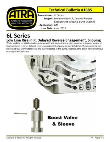
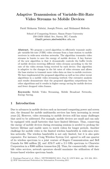
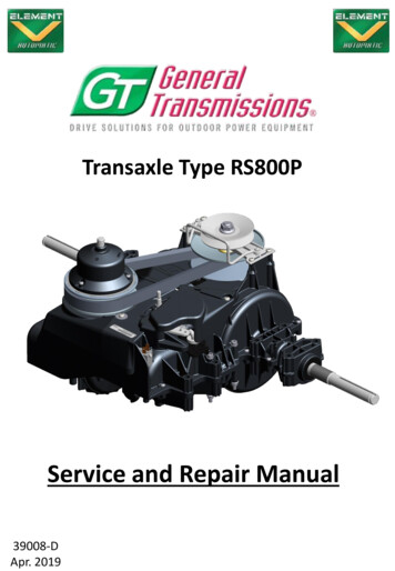
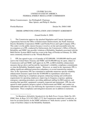
Analysis & Design of Transmission Tower & Monopole by using Manual Calculation & Software(IJSRD/Vol. 6/Issue 06/2018/026)1) To Calculate Design Wind PressureVd VR K1 K2 (From IS 802 part1/sec1-1995)VbVR K0Calculation of wind load (From IS 5613 part 1/ sec 1)B. Clearance RequirementVertical height of conductor above ground 7 m (IS 5613part2/sec1 1995)Vertical spacing between conductor 4.5m (IS 5613part2/sec1 1995Horizontal spacing between power conductor 6.25m (IS5613 part2/sec1 1995)Height between topmost conductor to earth wire H 3mTotal H 14.5 mFig. 1: Shows Resultant Displacement V/S Three LoadingConditions (132 KV & 220 KV Single Circuit)C. Calculation of Sag & TensionT UTSF.O.S.wl2Sagging 8TSagging 3.06m;Sag increased by 4%⸫ Sagging 3.18mTotal height of monopole 18mD. Calculation of Wind load:1) Transverse Load for ConductorFwc Pd Cdc L d GcTransverse load for ground wire:Fwg Pd Cdc L d GcTransverse load for insulator:Fwi Pd Cdi Ai GiVII. RESULT & DISCUSSIONFig. 2: Shows Compressive Stresses V/S Three LoadingConditions (132 KV & 220KV Single Circuit)Fig.1 shows resultant displacement on transmission towerand monopole of for single circuit 132 KV. Results showingdifferentiation in between monopole and transmission tower,which structure best for given loading condition.In resultant displacement for vertical displacementtransmission tower and monopole gives the nearby samedisplacement whereas in other two conditions transmissiontower gives the maximum displacement as compare tomonopole.Fig.2, 3, shows compression and tensile stresses forthree loading condition i.e. VLC, NC and BWC. Incompressive stresses and tensile stresses for all three loadconditions the transmission tower gives the maximumstresses as compare to the monopole. In quantity of steel thetransmission tower required the more steel becausetransmission tower has a different type of bracings and anglesection so it requires the more steel whereas, monopole istapered hallow section so it requires the lesser steel.Fig. 3: Shows Tensile Stresses V/S Three LoadingConditions (132 KV & 220 KV Single Circuit)All rights reserved by www.ijsrd.com103
Analysis & Design of Transmission Tower & Monopole by using Manual Calculation & Software(IJSRD/Vol. 6/Issue 06/2018/026)[2] Shivam Panwar, Yogesh Kaushik, “Structural Analysisand Design of Steel Transmission Tower in Wind ZoneII and IV- A Comparative Study” International Journalof Engineering Technology, Management and AppliedSciences, Volume 4, Issue 5, May 2016,[3] D.B.Sonowal, J.D.Bharali, “Analysis and Design of220kV Transmission Line Tower (Conventional Methodof Analysis and Indian Code Based Design)”, IOSRJournal of Mechanical and Civil Engineering, 2015, pp.40-49[4] M. Pavan Kumar, P. Markandeya Raju, “Effect of WindSpeed on Structural Behaviour of Monopole and SelfSupport Telecommunication Towers”, Asian Journal ofCivil Engineering, Volume 18, No.6, April 2017Fig. 4: Shows Quantity of Steel Required (132 KV & 220KV Single Circuit)VIII. CONCLUSIONThe present work attempt has been made to analysis anddesign of transmission tower and monopole by manualcalculation and using software. Based on the results obtainedfollowing conclusion appears to be justified:1) From results average displacement for transmissiontower is 43.05mm whereas for monopole is havingdisplacement is 4.10mm, this displacement found for132KV & 220KV single circuit structure. Where ‘K’Bracing used for the transmission tower and formonopole tapered section is used, here we conclude,monopole showing minimum displacement.2) As the bracing is changes the values of displacement andbending moment goes decreases for the transmissiontower even though the weight of structure increased dueto double circuit. But in monopole the values isincreases. From above values it concludes that themonopole is more effective and then transmission tower.3) From results, percentage of steel for single circuittransmission tower requires 60% greater than the singlecircuit monopole.4) From results of analysis the monopole required lesserpercentage of steel when compared to transmissiontower. From this it reveals that monopole getseconomical and lighter structure as compared totransmission tower.5) From calculations transmission tower requires the moreright of way (ROW) as compared to monopole. Toovercome these difficulties monopole suggests the bestoption for crowded area as well.6) From analysis it is observed that the values of maximumdisplacement and bending moment are higher formonopole as compare to transmission tower. This makesthe monopole structure less effective.Codes[5] IS 802 (part-1/sec-1): 1995 ‘Use of Structural Steel inOverhead Transmission Line Tower.’ Part 1: MaterialLoads and Permissible Stressses. Sec 1: materials andloads[6] IS 802 (part-1/sec-1): 1992 ‘Use of Structural Steel inOverhead Transmission Line Tower.’ Part 1: MaterialLoads and Permissible Stressses. Sec 2: Permissiblestresses.[7] IS 5613 (Part 2/ sec 1)-1995 ‘Code Of Practice ForDesign, Installation And Maintenance Of OverheadPower Lines’ Part 2: Lines Above 11kv And Upto AndIncluding 220kv.BOOKS:[8] P. Dayaratnam Design of Steel Structures.[9] M. Raghupati Design of Steel Structures.[10] DR. B.C. Punmia, Ashok Kumar Jain, and Arun KumarJain Design of Steel Structures[11] DR. Ram Chandra and Virendra Gehlot Design Of SteelStructure 2Websites[12] Shodhganga.inflibnet.ac.in[13] www.sciencedirect.com[14] www.wikipedia.com[15] Nptel.ac.inREFERENCES[1] Sai Avinash, Rajasekhar, “Analysis and Design ofTransmission Tower Using STAAD.PRO” InternationalJournal of Earth Sciences and Engineering, Volume 09,No. 03 June 2016 pp.310-313.All rights reserved by www.ijsrd.com104
Calculation & Software Miss. Pooja D. Vaidya1 Prof. Riyaz Sameer Shah2 1PG Student 2Assistant Professor 1,2Department of Civil Engineering 1,2Prof Ram Meghe Institute of Technology & Research, Badnera, Amravati-444701,Maharashtra, India Abstract— This research work is focused on comparison of transmission tower and monopole tower for different