Transcription
2MRI ScannersSince the beginning of M R I , technological advances have resulted in continual improvements in the speed at w h i c h data can be acquired, in theability to localize signal in space, and in the types of contrast that can bemeasured. Consequently, the practice of M R I today differs drastically fromthat of the early pioneers, and modern M R I scanners (Figure 2.1 A - C ) donot resemble the devices first used to detect nuclear magnetic resonance.However, the fundamental principles of M R I are unchanged. Just as Rabiused a strong magnetic field to measure spin properties of nuclei, today'sMRI scanners use a strong magnetic field to induce changes in proton spin.Just as Bloch detected nuclear i n d u c t i o n using transmitter and receivercoils, scanners now use similar coil systems to obtain MR signal. A n d justas Lauterbur manipulated magnetic field strength using changing gradientfields to create an image, every current M R I study relies on magnetic gradients for image acquisition. In this chapter, we identify the major components of M R I scanners, describe their use in practice, and discuss theirsafety implications.How MRI Scanners WorkThe three main components of an M R I scanner, as alluded to above, are thestatic magnetic field, radiofrequency coils, and gradient coils, w h i c htogether allow collection of images. Yet these are not the only componentsimportant for f M R I . Also necessary are s h i m m i n g coils, w h i c h ensure thehomogeneity of the static magnetic field; specialized computer systems forcontrolling the scanner and the experimental task; and physiological monitoring equipment. This section introduces these components and theirimplementation on modern M R I scanners (Figure 2.2). We w i l l return to adetailed discussion of how they are used to change the magnetic propertiesof atomic nuclei in Chapters 3 to 5.StaticMagneticFieldThe static magnetic field is an absolute necessity for M R I , p r o v i d i n g themagnetic in magnetic resonance imaging. Magnetic fields were discovered innaturally occurring rocks, k n o w n as lodestones, by ancient Chinese almost2000 years ago. By the eleventh century, the Chinese had recognized that the
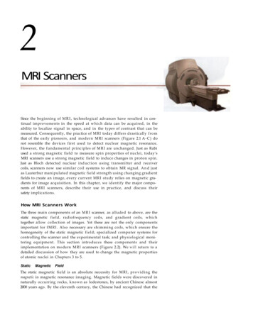
Figure 2.1Examples of MRI scanners. Most MRI scannersuse a closed-bore design, in which the patient/subject liesdown on a table at the front of the scanner and then ismoved back into the middle of the bore (i.e., central tube).Shown in (A) is a Signa series scanner from General Electric,and in (B) is a MAGNETOM Avanto scanner from Siemens.A small fraction of scanners use a more open design, suchas FONAR's 360 Open Sky scanner, shown in (C). In anopen scanner, the subject does not have to go into a tube, sothe chance of a claustrophobic reaction is reduced.However, it is more difficult to maintain a strong homogeneous static magnetic field in an open scanner, and thusmost scanners used for fMRI employ traditional closed-boredesigns. (A courtesy of GE Medical Systems, Waukesha,Wisconsin; B courtesy of Siemans AG, Berlin, Germany; Ccourtesy of Fonar Corporation, Melville, New York.)earth itself has a magnetic field, so that a magnet suspended in water w i l lorient itself along the earth's magnetic field lines (i.e., from north to south).The eventual rediscovery of magnetism centuries later by European scientists proved invaluable for subsequent nautical exploration, as shipsadopted magnetic compasses for directional guidance. M R I scanners usestrong static magnetic fields to align certain nuclei w i t h i n the human body(most commonly, hydrogen w i t h i n water molecules) to allow mapping oftissue properties.Some early M R I scanners used permanent magnets to generate the staticmagnetic fields used for imaging. Permanent magnets typically generateweak magnetic fields that are fixed by their material composition, and it isdifficult to ensure that their magnetic fields are not distorted over space.Another w a y of generating a magnetic field was discovered by the Danishphysicist Hans Oersted in 1820, when he demonstrated that a current-carrying w i r e influenced the direction of a compass needle below the wire, redirecting it perpendicularly to the direction of current. This relation was quantified later that year by the French physicists Jean-Baptiste Biot and FelixSavart, who discovered that magnetic field strength is in fact proportional tocurrent strength, so that by adjusting the current in a wire (or sets of wires),one could precisely control field intensity. These findings led to the development of electromagnets, w h i c h generate their fields by passing currentthrough tight coils of wire. Nearly all MRI scanners today create their staticmagnetic field through electromagnetism.
MRI Scanners29Figure 2.2 Schematic organization of the MRI scanner and computer control systems. Two systems are important for fMRI studies. The first is the hardware usedfor image acquisition, which in addition to the scanner itself consists of a series ofamplifiers and transmitters responsible for creating gradients and pulse sequences(shown in black), as well as recorders of MR signal from the head coil (shown inred). The second system is responsible for controlling the experiment in which thesubject participates and for recording behavioral and physiological data (shown ingreen).There are, in general, t w o criteria for a suitable magnetic field in MRI. Thefirst is uniformity (or homogeneity), and the second is strength. U n i f o r m i t yis necessary in that we want to create images of the body that do not dependon which MRI scanner we are using or h o w the body is positioned in thefield. If the magnetic field were inhomogeneous, the signal measured from agiven part of the body w o u l d depend upon where it was located in the magnetic field. (In fact, MRI takes advantage of this effect by introducing controlled changes in magnetic field strength by a d d i n g magnetic field gradients.) A simple design for generating a homogeneous magnetic field is thehomogeneity Uniformity over space andtime. In the context of MRI, a homogeneous magnetic field is one that hasthe same strength throughout a wideregion near the center of the scannerbore.
30Chapter Twosuperconducting electromagnets Aset of wires made of metal alloys thathave no resistance to electricity at verylow temperatures. By cooling the electromagnet to near absolute zero, astrong magnetic field can be generated with minimal electrical powerrequirements.cryogens Cooling agents used to reducethe temperature of the electromagnetic coils in an MRI scanner.Figure 2.3 Generation of a static magnetic field. The Helmholtz pair design (A)can generate a homogeneous magnetic field. It consists of a pair of circular currentloops that are separated by a distance equal to their radius; each loop carries thesame current. Modern MR scanners use a solenoid design (B), in which a coil ofwire is wrapped tightly around a cylindrical frame. By optimizing the locationsand density of the wire loops, a very strong and homogenous field can be constructed.Helmholtz pair (Figure 2.3A), w h i c h is a pair of circular w i r e loops thatcarry identical current and are separated by a distance equal to the radius ofthe loops. An even more uniform magnetic field, however, can be generatedby a solenoid, w h i c h is constructed by w i n d i n g w i r e in a helix around thesurface of a cylindrical form (Figure 2.3B). If the solenoid is long comparedw i t h its cross-sectional diameter, the internal field near its center is highlyhomogeneous. Modern magnets are based on a combination of these classicdesigns, w i t h the density of wires, and therefore the electrical current,numerically optimized to achieve a homogeneous magnetic field of thedesired strength.Field strength, in contrast to uniformity, requires force rather than finesse.To generate an extremely large magnetic field, one can inject a huge electriccurrent into the loops of wire. For example, the very large electromagnetsused to lift cars i n junkyards have magnetic fields on the order of 1 T, similarto that in the center of some M R I scanners. To generate this field, theyrequire enormous electrical power, and thus enormous expense. ModernM R I scanners use superconducting electromagnets whose wires arecooled by cryogens (e.g., l i q u i d helium) to reduce their temperature to nearabsolute zero. Coil windings are typically made of metal alloys such as niob i u m - t i t a n i u m , which when immersed in l i q u i d helium reach temperaturesof less than 12 K (-261 C). At this extremely low temperature, the resistancein the wires disappears, thereby enabling a strong and lasting electric current to be generated w i t h no power requirements and m i n i m a l cost.C o m b i n i n g the precision derived from numerical optimization of themagnetic coil design and the strength afforded by superconductivity, modern M R I scanners can have homogeneous and stable field strengths in therange of 1 to 9 T for human use and up to 20 T for animal use. Since main-
MRI Scannerstaining a field using superconductive w i r i n g requires little electricity, thestatic fields used in M R I are always active, even when no images are beingcollected. For this reason, the static field presents significant safety challenges, as w i l l be discussed later in this chapter.RadiofrequencyCoilsWhile a strong static magnetic field is needed for M R I , the static field itselfdoes not produce any MR signal. MR signal is actually produced by theclever use of t w o types of electromagnetic coils, k n o w n as transmitter andreceiver coils, that generate and receive electromagnetic fields at the resonant frequency of the atomic nuclei w i t h i n the static magnetic field. Thisprocess gives the name resonance to magnetic resonance imaging. Becausemost atomic nuclei of interest for M R I studies have their resonant frequencies in the radiofrequency portion of the electromagnetic spectrum (at typical field strengths for MRI), these coils are also called radiofrequency coils.Unlike the static magnetic field, the radiofrequency fields are turned on andoff during small portions of the image acquisition process and remain off forany other period. Radiofrequency coils are evaluated on the same criteria asthe static field: uniformity and sensitivity.An equilibrium state exists w h e n the human body is placed in any magnetic field, such that the net magnetization of atomic nuclei (e.g., hydrogen)within the body becomes aligned w i t h the magnetic field. The radiofrequency coils send electromagnetic waves that resonate at a particular frequency, as determined by the strength of the magnetic field, into the body,perturbing this e q u i l i b r i u m state. This process is k n o w n as excitation.When atomic nuclei are excited, they absorb the energy of the radiofrequency pulse. But, when the radiofrequency pulse ends, the hydrogen nucleireturn to the e q u i l i b r i u m state and release the energy that was absorbedduring excitation. The resulting release of energy can be detected by theradiofrequency coils, in a process k n o w n as reception. This detected electromagnetic pulse defines the raw MR signal.One can think of the measurement of MR signal through excitation andreception as analogous to the weighing of an object by l if ti ng and releasingit in a gravitational field. If an object sits motionless on a supporting surface, so that it is in an e q u i l i b r i u m state w i t h respect to gravitational force,we have no information about its weight. To weigh it, we first l i f t the objectto give it potential energy and then release it so that it transfers that energyback into the environment. The amount of energy it releases, whetherthrough impact against a surface or compression of a device like a spring(e.g., in a scale), provides an index of its weight. In the same way, we canperturb the magnetic properties of atomic nuclei (excitation) and thenmeasure the amount of energy returned (reception) d u r i n g their recovery toan equilibrium state.The amount of energy that can be transmitted or received by a radiofrequency coil depends upon its distance from the sample being measured. Inthe case of fMRI, the radiofrequency coils are typically placed immediatelyaround the head, either in a surface coil or volume coil arrangement (Figure2.4). Surface coils are placed directly on the imaged sample, that is, adjacentto the surface of the scalp for functional imaging. The design of surface coilsis based upon a single-loop inductor-capacitor (LC) circuit (Figure 2.4A).Within this circuit, the rapid charge and discharge of electricity between theinductor and capacitor generates an oscillating current that can be tuned tothe frequency of interest. Because of their close spatial p r o x i m i t y to thebrain, surface coils usually provide high imaging sensitivity and are often31radiofrequency coils Electromagneticcoils used to generate and receiveenergy at the sample's resonant frequency, which for field strengths typical to MRI is in the radiofrequencyrange.excitation The application of an electromagnetic pulse to a spin system tocause some of the spins to changefrom a low-energy state to a highenergy state.reception The process of receiving electromagnetic energy emitted by a sample at its resonant frequency (alsocalled detection). As spins return to alow-energy state following the cessation of the excitation pulse, they emitenergy that can be measured by areceiver coil.MR signal The current measured in adetector coil following excitation andreception.surface coil A radiofrequency coil that isplaced on the surface of the head, verynear to the location of interest. Surfacecoils have excellent sensitivity to signalfrom nearby regions but poor sensitivity to distant regions.volume coil A radiofrequency coil thatsurrounds the entire sample, withroughly similar sensitivity throughout.
32Chapter TwoFigure 2.4 Surface and volume coils. (A) Surface coils consist of a simple inductor (L) -capacitor (C) circuit, with additional resistance (R) also present. The rapidcharging and discharging of energy between the inductor and resistor generates anoscillating magnetic field. The signal from the surface coil is modulated by a variable capacitor (shown with the arrow). (B) Volume coils repeat the same LC circuitaround the surface of a cylinder. This results in better spatial coverage than is provided by a surface coil, at the expense of reduced local sensitivity. (C) A typicalsurface coil, and (D) volume coil.used for f M R I studies that are targeted toward one specific brain region,such as the visual cortex. The trade-off w i t h high local sensitivity is poorglobal coverage. Since the amount of signal recovered from a given part ofthe brain depends on its distance from the surface coil, areas very near thecoil provide a great deal of signal but areas far away provide very little (Figure 2.5A). Thus, the signal recovered by a surface coil is spatially inhomoge-
MRI Scannersphased array A method for arrangingmultiple surface detector coils toimprove spatial coverage while maintaining high sensitivity.Figure 2.5 Signal recorded from surface and volume radiofrequency coils. Theuse of a receiver coil adjacent to the surface of the skull can increase signal-to-noisein nearby brain regions (visible here as reduced graininess, e.g., at arrowed location), but the recorded signal will drop off in intensity as the distance from the coilincreases (A). Thus, the use of a single surface coil is more appropriate for fMRIstudies that are targeted toward a single brain region. Volume coils have relativelysimilar signal sensitivity throughout the brain (B), so they are more appropriate forfMRI studies that need coverage of multiple brain regions.neous, which makes a single surface coil inappropriate when whole-volumeimaging is desired.A second class of MR coil is the volume coil (Figure 2.4B), which providesuniform spatial coverage throughout a large volume. The basic element ofthe volume coil is the same LC circuit (described in the previous paragraph)for the surface coil. The LC circuit is replicated around a cylindrical surfaceto achieve u n i f o r m distribution of energy w i t h i n the enclosed volume (Figure 2.5B). The arrangement resembles a birdcage, and thus a volume coil issometimes referred to as a birdcage coil. Because the volume coil is fartherfrom the head than a surface coil, it has less sensitivity to the MR signal butmore even coverage across the brain.A compromise approach that combines the best features of both coil typesis to use a volume coil for exciting the imaging volume and a set of surfacecoils for receiving the MR signal. If multiple receiver coils are arranged in anoverlapping pattern k n o w n as a phased array, the spatial coverage of a single coil can be increased considerably while the high sensitivity of the coils ismaintained. Though sensitivity does change somewhat across the image, theuse of multiple receiver coils is an increasingly important technique in f M R I .The sensitivity of a radiofrequency coil is proportional to the strength ofthe magnetic field generated w i t h i n the coil by a unit current. Thus, a coilthat generates a strong magnetic field is also a sensitive receiver c o i l —a nexample of the principle of reciprocity. A stronger magnetic field can be generated by adding more wire loops to produce higher current density. Assuming that the coil resistance is not zero, because radiofrequency coils are nottypically superconducting, some energy w i l l be lost in the heat generation,which w i l l hamper the coil sensitivity. To obtain a quantitative measure ofthe coil sensitivity, a quality factor is defined as the ratio of the m axi mu m33
34Chapter Twogradient coils Electromagnetic coils thatcreate controlled spatial variation in thestrength of the magnetic field.energy stored and total energy dissipated per period. For an LC circuit, thatquantity can be represented as:M i n i m i z i n g resistance (R) thus boosts coil sensitivity.GradientCoilsThe ultimate goal of M R I is image generation. The combination of a staticmagnetic field and a radiofrequency coil allows detection of MR signal, butMR signal alone cannot be used to create an image. The fundamental measurement in M R I is merely the amount of current through a coil, w h i c h initself has no spatial information. By introducing magnetic gradients superimposed upon the strong static magnetic field, gradient coils provide the finalcomponent necessary for imaging. The purpose of a gradient coil is to causethe MR signal to become spatially dependent in a controlled fashion, so thatdifferent locations in space contribute differently to the measured signal overtime. Similar to the radiofrequency coil, the gradient coils are only used during image acquisition, as they are typically turned on briefly after the excitation process to provide spatial encoding needed to resolve an image.To make the recovery of spatial information as simple as possible, gradient coils are used to generate a magnetic field that increases in strengthalong one spatial direction. The spatial directions used are relative to themain magnetic field, w i t h z going parallel to the main field and x and ygoing perpendicularly to the main field. Like the previously discussed components of the scanner, gradient coils are evaluated on two criteria: linearity(comparable to the u n i f o r m i t y measure for the main magnet and theradiofrequency coils) and field strength.The simplest example of a linear gradient coil is a pair of loops w i t hopposite currents, k n o w n as a M a x w e l l pair (Figure 2.6A). A M ax we ll pair(A)Figure 2.6 C o i l a r r a n g e m e n t s f o r g e n e r a t i n g magnetic gradients. ( A ) S h o w s a M a x w e l l pair, t w o loopsw i t h o p p o s i n g c u r r e n t s , w h i c h generates m a g n e t i cf i e l d g r a d i e n t s a l o n g t h e d i r e c t i o n o f t h e m a i n magn e t i c f i e l d s . T h e c o n f i g u r a t i o n i n (B) i s k n o w n a s aG o l a y p a i r . I t a l l o w s g e n e r a t i o n o f m a g n e t i c f i e l d gradients perpendicular to the m a i n magnetic field.
MRIgenerates opposing magnetic fields w i t h i n t w o parallel loops, effectivelyproducing a magnetic field gradient along the line between the t w o loops.This design, in fact, is the basis for generating the z-gradient used today. Ofcourse, the z-gradient coils have a more complicated geometry than a simplepair, but the same concept underlies their design.The x- and y-gradients, also k n o w n as transverse gradients, are both created in the same fashion, since the coils that w r a p around the scanner arecircular and thus symmetrical across those directions. It is important tounderstand that the transverse gradients change the intensity of the mainmagnetic field across space (i.e., along z); they do not introduce smaller magnetic fields along x and y, as one might suppose. That is, the introduction ofan x-gradient, for example, makes the main magnetic field slightly weaker atnegative values along x and slightly stronger at positive values along x.Therefore, to generate a transverse gradient, one cannot simply place theMaxwell pair along the x or y axis (which w o u l d generate a magnetic fieldpointing perpendicular to the main field). Instead, scanners use a configuration similar to that shown in Figure 2.6B to generate these gradients. Thisslightly more complicated double-saddle geometry is k n o w n as a Golaypair. The final geometry that actually produces the x- or y-gradient field isnumerically optimized and contains many more w i n d i n g s than the simplesaddle coil shown here. Figure 2.7 illustrates the different patterns of coilwindings used for the magnetic gradients and the static magnetic field.The strength of the gradient coil is a function of both the current densityand the physical size of the coil. Increasing the current density by increasingthe electrical power supplied to the coil produces a stronger gradient field.Reducing the size of the coil, so that a given current travels through asmaller area, also produces a stronger gradient field. The trade-off betweenheld strength, size, and power is not linear. In fact, as the bore size increases,the power required for generating a gradient of the same strength increaseswith the 5 power of the bore size. The implications of this fact can beappreciated in a simple example. Consider that a physicist wants to increasethe bore size of a scanner by a factor of 2, while maintaining the same gradient strength. A l t h o u g h the bore size is only doubled, the power requirements increase by a factor of 2 , or 32. This constraint imposes a practicallimitation on the bore size of an M R I scanner.th5Some manufacturers have begun developing " h e a d - o n l y "MRI scanners for clinical and functional studies of the brain.Based upon w h a t you k n o w so far, w h a t w o u l d be the advantages of such scanners?Shimming CoilsIn an ideal MR scanner, the main magnet w o u l d be perfectly homogeneousand the gradient coils w o u l d be perfectly linear. This is hardly the case inreality, as the authors (and everyone w h o has ever conducted f M R I studies!)can attest. MRI scanners must correct for inhomogeneities in the static magnetic field; in some locations the field may be too strong, in others too weak.This process is analogous to what we do when a table is r o c k i n g —w e simplyput a wedge under one of the uneven legs to make it stable. This wedge iscalled a shim. In the scanner, additional coils generate high-order compensatory magnetic fields (like the analogous wedges) that correct for the inho-Scanners35
36Chapter Two(B)(A)Figure 2.7 Generation of x-, y-, and z-gradients andthe static magnetic field (B ). (A) A number of different electromagnetic coils are used within a single MRIscanner. (B) The coils are arranged as a series of concentric circles, beginning with the gradient coils at theinterior and followed by the shimming coils and thenthe static field coils. The x- and y-gradients are generated using the Golay pair arrangement, and the onlydifference between them is that one is rotated 90 from the other. The z-gradient is generated using theMaxwell pair arrangement. The shimming coils arenot shown here due to their complexity; as discussedin the text, there may be many different coil typesdepending on the scanner. Finally, the static field isgenerated using a series of Helmholtz pairs, with thedistance between the pairs corresponding to theirradius.0shimming coils Electromagnetic coilsthat compensate for inhomogeneitiesin the static magnetic field.mogeneity of the magnetic field. These coils, intuitively, are named shimming coils.Typically, shimming coils can produce first-, second-, or even third-ordermagnetic fields. For example, an x-shimming coil w o u l d generate a magnetic field that depends on position along the x-axis (first-order), w h i l e anx - s h i m m i n g coil could generate a magnetic field that depends upon thecube of the x position (third-order). Combinations of these high-order mag3
MRI Scannersnetic fields can usually correct for the inhomogeneity of a typical magnet sothat the magnetic field is u n i f o r m to roughly 0.1 part per m i l l i o n (ppm) overa spherical volume of 20-cm diameter. For a 1.5-T magnet, this represents adeviation of only 0.00000015 Tesla.Unlike the other magnetic fields, the shim fields are adjusted for eachsubject. For f M R I studies, each person's head distorts the magnetic fieldslightly differently. Shimming procedures used in f M R I thus account for thesize and shape of the subject's head so that the u n i f o r m i t y of the magneticfield can be optimized over the brain. Also unlike the radiofrequency andgradient coils, which are turned on and off throughout the imaging session,the shimming coils are usually adjusted once and then left on for the duration of the session.ComputerHardwareandSoftwareDigitizing, decoding, and displaying MR images require a considerableamount of computer processing power. A l l M R I scanners are equipped w i t hat least one central computer to coordinate all hardware components (e.g.,gradient coils, radiofrequency coils, digitizers), and often mul tipl e computers are used to control separate hardware clusters. The computer type,processor, and operating system vary greatly across scanner manufacturers.In addition to the hardware requirements, t w o types of specialized softwareare needed for f M R I . The first type of software sends a series of instructionsto the scanner hardware so that images can be acquired. These programs,often called pulse sequences, coordinate a series of commands to turn on oroff certain hardware at certain times. The type of pulse sequence used determines which kind of images are acquired. Usually the selection of parameters for a pulse sequence is done via a graphic user interface (Figure 2.8).The second type of software is the reconstruction and analysis package tocreate, display, and analyze the images. Creation of many images, especiallyanatomical, is done online at the scanner, but often images are sent to othermore powerful computers for reconstruction and/or analysis. We w i l l discuss the principles of image formation and pulse sequence generation inChapters 4 and 5.ExperimentalControlSystemTo induce changes in brain function in response to task manipulations, anexperimental control system is necessary. A l t h o u g h the particular hardwareand software used will differ across laboratories, there are three basic components. First, the control system must generate the experimental stimuli, whichmay include pictures or words that subjects see, sounds that subjects hear, oreven taps on the skin that subjects feel. Since normal computer monitors cannot go into the strong magnetic field of the scanner, visual stimuli are oftenshown to the subject by custom virtual-reality goggles that are MR compatible or by projecting an image onto a screen in the bore of the scanner. Second,the control system must record behavioral responses made by the subject,such as pressing a button or moving a joystick. Usually, both the timing andthe accuracy of the response are measured. Third, the presentation of stimuliand recording of responses must be synchronized to the t i m i n g of imageacquisition, so that the experimental paradigm can be matched to the f M R Idata. This may be done through direct electrical connection of the scannerhardware and experimental control system, so that starting the scanner sendsan electrical pulse to the control system that triggers the start of the experiment as well. Specialized software packages are often used for the experimental control system in conjunction w i t h standard personal computers. The37pulse sequence A series of changingmagnetic field gradients and oscillatingelectromagnetic fields that allows theMRI scanner to create images sensitiveto a particular physical property.
38Chapter TwoFigure 2.8 A graphic user interface used to control an MRI scanner. The operator ofan MRI scanner will use an interface similar to this one to select the pulse sequenceparameters for a given study. (Courtesy of General Electric Medical Systems,Waukesha, Wisconsin.)key challenge for any experimental setup is to ensure that the equipmentused in the scanner room, such as display devices or joysticks, is not attractedby the strong magnetic fields and does not interfere w i t h imaging.PhysiologicalMonitoringEquipmentMany M R I scanners have equipment dedicated to recording physiologicalmeasures like heart rate, respiratory rate, exhaled C 0 , and skin conductance. In clinical studies, such equipment allows attending physicians tomonitor patients' vital signs. If a patient has trouble br
By the eleventh century, the Chinese had recognized that the . Figure 2.1 Examples of MRI scanners. Most MRI scanners use a closed-bore design, in which the patient/subject lies . Coil windings are typically made of metal alloys such as nio-bium-titanium, which when immersed in liquid helium reach temperatures of less than 12 K (-261 C). At .