Transcription
SLC 500 SYSTEMSSELECTION GUIDEBULLETIN 1746 AND 1747
Important User InformationSolid state equipment has operational characteristics differing from those of electromechanical equipment. Safety Guidelines for the Application,Installation and Maintenance of Solid State Controls (publication SGI-1.1 available from your local Rockwell Automation sales office or online athttp://rockwellautomation.com/literature) describes some important differences between solid state equipment and hard-wired electromechanicaldevices. Because of this difference, and also because of the wide variety of uses for solid state equipment, all persons responsible for applying thisequipment must satisfy themselves that each intended application of this equipment is acceptable.In no event will Rockwell Automation, Inc. be responsible or liable for indirect or consequential damages resulting from the use or application of thisequipment.The examples and diagrams in this manual are included solely for illustrative purposes. Because of the many variables and requirements associatedwith any particular installation, Rockwell Automation, Inc. cannot assume responsibility or liability for actual use based on the examples anddiagrams.No patent liability is assumed by Rockwell Automation, Inc. with respect to use of information, circuits, equipment, or software described in thismanual.Reproduction of the contents of this manual, in whole or in part, without written permission of Rockwell Automation, Inc., is prohibited.Throughout this manual, when necessary, we use notes to make you aware of safety considerations.WARNINGIdentifies information about practices or circumstances that can cause an explosion in a hazardous environment, which maylead to personal injury or death, property damage, or economic loss.IMPORTANTIdentifies information that is critical for successful application and understanding of the product.ATTENTIONIdentifies information about practices or circumstances that can lead to: personal injury or death, property damage, oreconomic loss. Attentions help you identify a hazard, avoid a hazard, and recognize the consequence.SHOCK HAZARDLabels may be on or inside the equipment, such as a drive or motor, to alert people that dangerous voltage may be present.BURN HAZARDLabels may be on or inside the equipment, such as a drive or motor, to alert people that surfaces may reach dangeroustemperatures.Allen-Bradley, Rockwell Automation, SLC 500, RSLogix 500, RSLinx, RSNetworx, and TechConnect are trademarks of Rockwell Automation, Inc.Trademarks not belonging to Rockwell Automation are property of their respective companies.
Benefits Powerful, yet affordable – SLC 500 programmable controllers provide excellentvalue with extensive capabilities to address a broad range of applications includingmaterial handling, HVAC control, high speed assembly operations, small processcontrol, simple motion control, and SCADA. Modularity – Modular processes, power supplies, I/O, memory options, andcommunication interfaces allow for a configurable and expandable system.Configure your system for the number of I/O, the amount of memory, and thecommunication networks needed. Later, you can expand the system by addingI/O, memory, or communication interfaces. Advanced instruction set – Includes indirect addressing, high level mathcapability, and a compute instruction. Communication network versatility Choose from on-board Ethernet, DH , or DH-485, as well as options forControlNet, DeviceNet, or Remote I/O communications. Broad selection of I/O – Select from over 60 modules to control discrete, analog,and temperature signals. Third-party specialty modules are also available fromEncompass partners to customize control solutions for your application needs.Industrially hardened product - Designed to withstand the vibrations, thermalextremes, and electrical noise associated with harsh industrial environments. Windows programming software – RSLogix 500 programming softwaremaximizes productivity by simplifying program development andtroubleshooting.Allen-Bradley, ControlLogix, PLC-5, RSLinx, VersaView, Block I/O, CompactLogix,Flex, FlexLogix, MicroLogix, PanelView, RSLogix, RSNetWorx and SLC are trademarksof Rockwell Automation.Trademarks not belonging to Rockwell Automation are the property of their respectivecompanies.
SLC 500 System OverviewThe Allen-Bradley SLC 500 is a small chassis-based family of programmable controllers,discrete, analog, and specialty I/O, and peripheral devices. The SLC 500 family deliverspower and flexibility with a wide range of communication configurations, features, andmemory options. The RSLogix 500 ladder logic programming package provides flexibleeditors, point-and-click I/O configuration, and a powerful database editor, as well asdiagnostic and troubleshooting tools to help you save project development time andmaximize productivity.Typical SystemsTopicPageSelect SLC 500 I/O Modules2Select Network Communications2Select an SLC 500 Processor69Select an SLC 500 Chassis75Select SLC 500 Power Supplies79Select Programming Software91Summary101With up to 64 K of configurable data/program memory available and over 60 types ofI/O modules, as well as a choice of networking options, the SLC system provides apowerful solution for stand-alone or distributed industrial control.
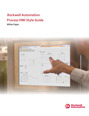
System Overview3Local SystemsI/O ModulesProcessorPower SupplyAt minimum, a modular hardware SLC 500 control system consists of a processormodule and I/O modules in a single 1746 chassis with a power supply.I/O ModulesI/O ModulesChassis Interconnect CableI/O ModulesChassis Interconnect CablePower SupplyPower SupplyProcessorPower SupplyYou can configure a system with one, two, or three local chassis, for a maximum total of30 local I/O or communication modules. You connect multiple local chassis togetherwith chassis interconnect cables to extend the backplane signal lines from one chassis toanother.Distributed SystemsMore complex systems can use: distributed I/O.Publication 1747-SG001E-EN-E - February 2013
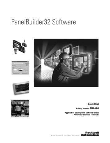
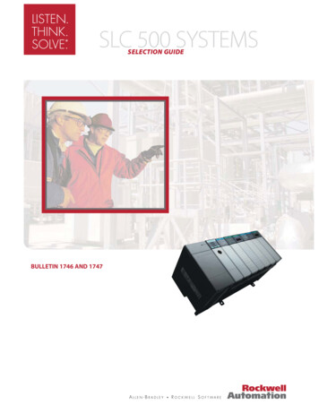
4System Overview multiple controllers joined across networks. I/O in multiple platforms that are distributed in many locations and connectedover multiple I/O links.Choose the processor module with the on-board communication ports you need. Youoptionally add modules to provide additional communication ports for the processor. ForI/O in locations remote from the processor, you can choose between a ControlNet,DeviceNet, or Univeral I/O link. A communication interface module is required in boththe local and remote chassis.Depending upon the communication ports available on your particular SLC controlsystem, you can select operator interfaces that are compatible.ComputersProcessorsHMIsInternet BrowserDH-485 NetworkEtherNet/IP NetworkDH NetworkDF1 NetworkControlNet NetworkDeviceNet NetworkControlNet LinkSLC ProcessorModuleCommunicationinterface modules inthe I/O chassiswhere the SLCprocessor resides.DeviceNet LinkRemote I/OModulesUniversal Remote I/O Link1746 Chassis Backplane1746 I/O modules inthe I/O chassis localto the SLC processor.A maximum of960 I/O.Laying Out the SystemLay out the system by determining the amount of I/O necessary, the networkconfigurations, and the placement of components in each location. Decide at this timewhether each chassis will have its own controller or a networked solution.SLC 500 processors are available with a large range of memory sizes (1 K 64 K) and cancontrol up to 4096 input and 4096 output signals. All modular processors except theSLC 5/01 processor are capable of controlling remotely located I/O. By adding an I/Oscanner module, you can use these processors to control/monitor these remotely locatedI/O across ControlNet, DeviceNet, and Universal Remote I/O links.Publication 1747-SG001E-EN-E - February 2013
System Overview5SLC 500 processors are single-slot modules that you place into the left-most slot of a1746 I/O chassis. For I/O in a location remote from the processor, the I/O adapter is asingle-slot module that you place in the left-most slot of the I/O chassis. SLC 500modular systems provide separate power supplies which must be mounted directly on theleft end of the 1746 I/O chassis.The 1746 I/O chassis are designed for back-panel mounting and available in sizes of 4, 7,10, or 13 module slots. The 1746 I/O modules are available in densities up to a maximumof 32 channels per module.CommunicationsEvaluate what communications need to occur. Knowing your communicationsrequirements will help you determine which processor and which communicationsdevices your application might require.An SLC processor communicates across the 1746 backplane to 1746 I/O modules in thesame chassis in which the processor resides. Various models of SLC processors havevarious on-board ports for communication with other processors or computers. Also,separate modules are available to provide additional communication ports forcommunication with other processors, computers, and remotely located I/O.Each processor has one or two built-in ports for either EtherNet/IP, DH , DH-485, orRS-232 (DF1, ASCII, or DH-485 protocol) communication.In addition to the on-board ports available with SLC processors, you have the option ofproviding another communication port for an SLC processor by adding acommunication module.Adapter modules for 1746 I/O are available for ControlNet and Universal Remote I/Olinks. An I/O adapter module in a chassis with I/O modules interfaces the I/O moduleswith the I/O link for communication with a scanner port for a processor at anotherlocation.SLC 500 CommonSpecificationsThe following specifications apply to all SLC 500 modular components unless noted.Environmental SpecificationsAttributeValueTemperature, operatingIEC 60068-2-1 (Test Ad, Operating Cold),IEC 60068-2-2 (Test Bd, Operating Dry Heat),IEC 60068-2-14 (Test Nb, Operating Thermal Shock):0 60 C (32 140 F)Temperature, nonoperatingIEC 60068-2-1 (Test Ab, Unpackaged Nonoperating Cold),IEC 60068-2-2 (Test Bb, Unpackaged Nonoperating Dry Heat),IEC 60068-2-14 (Test Na, Unpackaged Nonoperating Thermal Shock):-40 85 C (-40 185 F)Relative humidityIEC 60068-2-30 (Test Db, Unpackaged Damp Heat):5 95% without condensationPublication 1747-SG001E-EN-E - February 2013
6System OverviewEnvironmental SpecificationsAttributeValueVibration, operatingIEC 60068-2-6 (Test Fc, Operating):1 g @ 5 2000 HzVibration, nonoperating2.5 g @ 5 2000 HzShock, operating30 g (3 pulses, 11 ms) – for all modules except relay contact10 g (3 pulses, 11 ms) – for relay contact modules 1746-OWx and1746-IOx comboShock, nonoperating50 g, 3 pulses, 11 msFree fall (drop test)Portable, 2.268 kg (5 lb) or less @ 0.762 m (30 in.), six dropsPortable, 2.268 kg (5 lb) or less @ 0.1016 m (4 in.), three flat dropsIsolation voltageIsolation between communication circuits: 500V DCIsolation between backplane and I/O: 1500V ACCertificationsCertifications whenproduct is marked(1)ValueULUL Listed for Class I, Division 2 Group A,B,C,D Hazardous Locations. SeeUL File E10314.c-ULUL Listed for Class I, Division 2 Group A,B,C,D Hazardous Locations,certified for Canada. See UL File E10314.CEEuropean Union 2004/108/EC EMC Directive, compliant with:EN 61000-6-2; Industrial ImmunityEN 61000-6-4; Industrial EmissionsEN 61131-2; Programmable Controllers (Clause 8, Zone A & B)European Union 2006/95/EC LVD, compliant with:EN 61131-2; Programmable Controllers (Clause 11)C-TickAustralian Radiocommunications Act, compliant with:AS/NZS CISPR 11; Industrial EmissionsKCKorean Registration of Broadcasting and Communications Equipment,compliant with:Article 58-2 of Radio Waves Act, Clause 3(1) See the Product Certification link at cation/ forDeclarations of Conformity, Certificates, and other certification details.Publication 1747-SG001E-EN-E - February 2013
System OverviewSLC 500 System Checklist7Use the following Checklist as a guide to completing your own system specification. StepSee1 Select I/O Modulespage 9 consider using an interface module or pre-wired 1492cables use a spreadsheet to record your selections2 Select Communication Modules/Devicespage 51 determine your network communication requirementsand select the necessary communicationmodules/devices include appropriate communication cables record your module/device selections on the systemspreadsheet3 Select an SLC 500 Processorpage 69 choose a processor based on memory, I/O, performance,programming requirements, and communication options4 Select an SLC 500 Chassispage 75 determine the number of chassis and any interconnectcables required based on the physical configuration ofyour system5 Select an SLC 500 Power Supplypage 79 use the power supply loading worksheet to ensuresufficient power for your system consider future system expansion when selecting apower supply6 Select Programming Softwarepage 91 select the appropriate package of RSLogix 500Programming Software for your applicationPublication 1747-SG001E-EN-E - February 2013
8System OverviewNotes:Publication 1747-SG001E-EN-E - February 2013
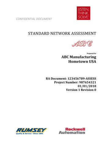
Step 1 - Select: I/O modules – available in avariety of densities and voltageoptions. Some modules havediagnostic features, individuallyisolated inputs/outputs orelectronic protection. interface modules (IFMs) orprewired cables (optional)1746 Digital I/O modulesSelect SLC 500 I/O ModulesDigital I/O modules, analog I/O modules, and specialty temperature, counting, processcontrol, and BASIC language modules are available to help you create a custom solutionfor your application.Digital I/O modules are available with 4, 8, 16, or 32 channels and in a wide variety ofI/O voltages (including AC, DC, and TTL). Combination modules with 2 inputs/2outputs, 4 inputs/4 outputs, and 6 inputs/6 outputs are also available.Terminals on the 4, 8, 12, and 16-channel modules have self-lifting pressure plates thataccept two 14 AWG (2 mm2) wires. LED indicators on the front of each module displaythe status of each I/O point.32-channel I/O modules are equipped with a 40-pin, MIL-C-83503 type header and aremovable wiring connector (1746-N3). The connector can be assembled with the wiretype and length of your choice.Output modules are available with solid-state AC, solid-state DC, and relay contact typeoutputs. High current solid-state output modules, catalog numbers 1746-OBP16, 1746OVP16, and 1746-OAP12, have fused commons with a blown fuse LED indication. The
10Select SLC 500 I/O Modules1746-OB16E, 1746-OB6EI, and 1746-OB32E modules provide electronic protectionfrom short circuit and overload conditions.Wiring of 16 and 32-channel modules can also be accomplished with a bulletin 1492interface module and pre-wired cable. All 16-channel I/O modules and catalog numbers1746-OX8, 1746-OBP8, 1746-OAP12, 1746-IO12 are equipped with color-codedremovable terminal blocks.Digital I/O Module OverviewCatalog NumberVoltage CategoryI/O PointsDescriptionFor Detailed Specifications, See1746-IB824V DC8Current Sinking DC Input Module1746-IB1624V DC16Current Sinking DC Input ModuleSinking DC Input Modulespage 111746-IB3224V DC32Current Sinking DC Input Module1746-ITB1624V DC16Fast Response DC Sinking Input Module1746-IC1648V DC16Current Sinking DC Input Module1746-IH16125V DC16Current Sinking DC Input Module1746-IV824V DC8Current Sourcing DC Input Module1746-IV1624V DC16Current Sourcing DC Input Module1746-IV3224V DC32Current Sourcing DC Input Module1746-ITV1624V DC16Fast Response DC Sourcing Input Module1746-IG16(1)5V DC16Current Sourcing TTL Input Module1746-OB6EI24V DC6Electronically Protected Isolated Sourcing DCOutput Module1746-OB824V DC8Current Sourcing DC Output Module1746-OB1624V DC16Current Sourcing DC Output Module1746-OB16E24V DC16Electronically Protected Current Sourcing DCOutput Module1746-OB3224V DC32Current Sourcing DC Output Module1746-OB32E24V DC32Electronically Protected Current Sourcing DCOutput Module1746-OBP824V DC8High Current Sourcing DC Output Module1746-OBP1624V DC16High Current Sourcing DC Output Module1746-OV824V DC8Current Sinking DC Output Module1746-OV1624V DC16Current Sinking DC Output Module1746-OV3224V DC32Current Sinking DC Output Module1746-OVP16(2)24V DC16High Current Sinking DC Output Module1746-OG16(1)5V DC16Current Sinking TTL Output ModuleDC Modules(2)AC ModulesPublication 1747-SG001E-EN-E - February 2013Sourcing DC Input Modulespage 12Sourcing DC Output Modulespage 13Sinking DC Output Modulespage 12
Select SLC 500 I/O Modules11Digital I/O Module OverviewCatalog NumberVoltage CategoryI/O PointsDescriptionFor Detailed Specifications, See1746-IA4100/120V AC4120V AC Input Module1746-IA8100/120V AC8120V AC Input ModuleAC Input Modulespage 141746-IA16100/120V AC16120V AC Input Module1746-IM4200/240V AC4240V AC Input Module1746-IM8200/240V AC8240V AC Input Module1746-IM16200/240V AC16240V AC Input Module1746-OA8120/240V AC8120/240V AC Output Module1746-OA16120/240V AC16120/240V AC Output Module1746-OAP12(2)120/240V AC12High Current 120/240V AC Output Module1746-IN1624V AC/DC1624V AC/DC Input ModuleAC Input Modulespage 141746-OW4(2)AC/DC Relay4Relay (Hard Contact) Output ModuleRelay Output Modulespage 161746-OW8(2)AC/DC Relay8Relay (Hard Contact) Output Module1746-OW16(2)AC/DC Relay1746-OX8(2)AC/DC Relay8Relay (Hard Contact) Output Module1746-IO4(2)120V ac (Inputs) 100/120VAC (Relay Contact Outputs)2 In2 OutCombination Input/Output Module1746-IO8(2)120V AC (Inputs) 100/120VAC (Relay Contact Outputs)1746-IO12(2)120V AC (Inputs) 100/120VAC (Relay Contact Outputs)4 In4 OutCombination Input/Output Module1746-IO12DC24V DC (Inputs) 100/120VAC (Relay Contact Outputs)6 In6 OutCombination Input/Output ModuleAC Output Modulespage 15AC/DC ModulesRelay (Hard Contact) Output ModuleCombination I/O Modulespage 17Combination Input/Output Module(1) Not CE marked.(2) Certified for Class 1, Division 2 hazardous location by C-UL only.Sinking DC Input 6-IC161746-IH16(1)1746-ITB16Number of Inputs81632321616Points Per Common816881616Voltage Category24V DC48V DC125V DCOperating Voltage Range10 30V DCBackplane Current (mA) @ 5V50 mABackplane Current (mA) @ 24V0 mA15 30VDC @ 50 C(122 F)15 26.4VDC @ 60 C(140 F)30 60V DC @ 55 C(131 F)30 55V DC @ 60 C(140 F)50 mA50 mA50 mA0 mA0 mA0 mA24V DC90 146V DC10 30V DC0 mA0mA(2)Publication 1747-SG001E-EN-E - February 2013
12Select SLC 500 I/O ModulesSinking DC Input tage, Off-State Input, max.5.0V DCNominal Input Current8 mA @ 24V DC5.1 mA @24V DCCurrent, Off-State Input, Max.1 mA1.5 mASignal On Delay, Max8 ms max3 ms maxSignal Off Delay, Max8 ms max3 ms max1746-IC161746-IH16(1)1746-ITB1610V DC20V DC5V DC4.1 mA @ 48V DC2.15 mA @ 125V DC2.25 mA @ 132V DC8 mA @ 24V DC0.8 mA1.5 mA4 ms max9 ms max0.30 ms max4 ms max9 ms max0.50 ms max(1) If the input module is connected in parallel with an inductive load, use surge suppression across the load to protect the input module from damage caused by reversevoltage. Refer to the SLC 500 Modular Hardware Style User Manual, publication 1747-UM011, for more information on surge suppression.(2) Maixumum Points ON Simultaneously: 16 @ 146V DC and 30 C (86 F); 12 @ 146V DC and 50 C (122 F); 14 @ 132V DC and 55 C (131 F); 16 @ 125V DC and60 C (140 F).Sourcing DC Input 6-IV321746-ITV16Number of inputs168163216Points per common16816816Voltage category5V DC24V DC24V DC24V DC24V DCOperating voltage range4.5 5.5V DC(1)10 30V DC15 30V DC@ 50 C (122 F)15 26.4V DC@ 60 C (140 F)10 30V DCBackplane current (mA) @ 5V140 mA50 mA85 mA50 mA85 mABackplane current (mA) @ 24V0 mA0 mA0 mA0 mA0 mAVoltage, off-state input, max.2 5.5V DC5.0V DC5.0V DC5.0V DC5.0V DCNominal input current3.7 mA @ 5V DC 8 mA @ 24V DC5.1 mA @ 24V DC8 mA @ 24V DCCurrent, off-state input, max.4.1 mA1 mA1.5 mA1.5 mASignal on delay, max0.25 ms max8 ms max3 ms max0.30 ms maxSignal off delay, max0.50 ms max8 ms max3 ms max0.50 ms max(2)(1) 50 mV peak-to-peak ripple (max.)(2) Typical signal delay for this module: ON 0.1 ms, OFF 0.25 ms @ 24V DC.Sinking DC Output 6-OV321746-OVP16(5)Number of outputs168163216Points per common168161616Voltage category5V DC24V DCOperating voltage range4.5 5.5V DC(2)10 50V DC5 50V DC20.4 26.4V DCBackplane current (mA)@ 5V180 mA135 mA270 mA190 mA250 mABackplane current (mA)@ 24V0 mA0mA0 mA0 mA0 mAPublication 1747-SG001E-EN-E - February 2013
Select SLC 500 I/O Modules13Sinking DC Output 6-OV321746-OVP16(5)Voltage drop, on-stateoutput, max.—1.2V @ 1.0 A1.2V @ 0.5 A1.2V @ 0.5 A1.0 V @ 1.0 ALoad current, min.0.15 mA1 mA1 mA1 mA1 mALeakage current, off-stateoutput,max0.1 mA1 mA(3)1 mA(3)1 mA(3)1 mA(3)Signal On Delay, max(resistive load)0.25 ms0.1 ms0.1 ms0.1 ms0.1 ms(6)Signal Off Delay, max(resistive load)0.50 ms1.0 ms1.0 ms1.0 ms1.0 msContinuous current permoduleN/A8.0 A @ 30 C (86 F)4.0 A @ 60 C (140 F)8.0 A @ 0 60 C(32 140 F)6.4 A @ 0 60 C(32 140 F)Continuous current perpoint24 mA1.0 A @ 30 C (86 F)0.5 A @ 60 C (140 F)0.50 A @ 30 C0.25 A @ 60 C1.5 A @ 30 C (86 F)1.0 A @ 60 C (140 F)(7)Surge current per pointfor 10 ms(1)N/A3.0 A1.0 A @ 30 C (86 F)1.0 A @ 60 C (140 F)4.0 A(8)0.50 A @30 C (86 F)0.25 A @60 C (140 F)(4)(1) Repeatability is once every 1 s @ 30 C (86 F). Repeatability is once every 2 s @ 60 C (140 F).(2) 50 mV peak to peak ripple, max.(3) To limit the effects of leakage current through solid-state outputs, a loading resistor can be connected in parallel with your load. For transistor outputs, 24V DC operation,use a 5.6 K Ω, 1/2 W resistor.(4) Recommended surge suppression: For transistor outputs, when switching 24V DC inductive loads, use a 1N4004 diode reverse-wired across the load. Refer to the SLC 500Modular Hardware Style User Manual, publication 1747-UM011, for more information on surge suppression.(5) The 1746-OVP16 module features a fused common and blown fuse LED indicator.(6) Fast turn-off modules provide fast OFF delay for inductive loads. Fast turn-off delay for inductive loads is accomplished with surge suppressors on this module. Asuppressor at the load is not needed unless another contact is connected in series. If this is the case, a 1N4004 diode should be reverse wired across the load. This defeatsthe fast turn-off feature. Comparative OFF delay times for 1746-OB8, 1746-OV8 and fast turn-off modules, when switching Bulletin 100-B110 (24 W sealed) contactor, are:1746-OB8 and 1746-OV8 modules OFF delay 152 ms; fast turnoff modules OFF delay 47 ms.(7) Fast off-delay for inductive loads is accomplished with surge suppressors on the 1746-IB6EI and 1746-OBP8 series B and later, 1746-OB16E series B and later, 1746-OBP16and 1746-OVP16 modules. A suppressor at the load is not needed unless another contact is connected in series. If this is the case, a 1N4004 diode should be reverse-wiredacross the load. This defeats the fast turn-off feature.(8) Surge current 32 A per module for 10 ms.Sourcing DC Output 46-OB16E1746-OB321746-OB32ENumber of outputs 6 d32328ElectronicallyProtected16(5)Points percommonIndividuallyisolated816161616416Voltage category24V DCOperating voltagerange10 30V DC10 50V DC10 30V DC5 50V DC10 30V DC20.4 26.4V DCBackplane current(mA) @ 5V46 mA135 mA280 mA135 mA190 mABackplane current(mA) @ 24V0 mA0 mA0 mA0 mA0 mA0 mA1746-OBP8(4)1746-OBP16135 mA250 mA0 mA0 mAPublication 1747-SG001E-EN-E - February 2013
14Select SLC 500 I/O ModulesSourcing DC Output 46-OB16E1746-OB32Voltage drop,on-state output,max.1.0V @ 2.0 A1.2V @1.0 A1.2V @0.5 A1.0V @ 0.5 A1.2V @ 0.5 ALoad current, min.1 mA1 mA1 mA1 mA1 mALeakage current,off-stateoutput,max1 mA1 mA1 mA1 mASignal on delay,max (resistiveload)1.0 ms(2)0.1 ms0.1 msSignal off delay,max (resistiveload)2.0 ms1.0 ms1.0 msContinuouscurrent permodule12.0 A @ 0 60 C(32 140 F)8.0 A @ 30 C (86 F)4.0 A @ 60 C (140 F)8.0 A @ 0 60 C (32 140 F)Continuouscurrent per point2.0 A @ 0 60 C(32 140 F)(3)1.0 A @ 30 C (86 F)0.50 A @ 60 C(140 F)1.0 A @ 30 C (86 F)0.50 A @ 60 C (140 F)(4)0.50 A @ 30 C (86 F)0.25 A @ 60 C (140 F)2.0 A @ 0 60 C (32 140 F)(4)Surge current perpoint for 10 ms(1)4.0 A3.0 A2.0 A1.0 A @ 30 C (86 F)1.0 A @ 60 C (140 F)4.0 A0.50 A @ 30 C (86 F)0.25 A @60 C(140 F)1746-OB32E1746-OBP8(4)1746-OBP161.0V @ 2.0 A1.0V @ 1.0 A1 mA1 mA1 mA1 mA1 mA1 mA1 mA1.0 ms(3)0.1 ms1.0 ms1.0 ms(3)0.1 ms(3)1.0 ms1.0 ms2.0 ms2.0 ms1.0 ms6.4 A @0 60 C(32 140 F)1.5 A @ 30 C(86 F)1.0 A @ 60 C(140 F)(4)(1) Repeatability is once every 1 s @ 30 C (86 F). Repeatability is once every 2 s @ 60 C (140 F).(2) Fast turn-off modules provide fast OFF delay for inductive loads. Comparative OFF delay times for 1746-OB8, 1746-OV8 and fast turn-off modules, when switching Bulletin100-B110 (24 W sealed) contractor, are: 1746-OB8 and 1746-OV8 modules OFF delay 152 ms; fast turn-off modules OFF delay 47 ms.(3) Fast off-delay for inductive loads is accomplished with surge suppressors on the 1746-IB6EI, 1746-OBP8 series B and later, 1746-OB16E series B and later, 1746-OBP16,and 1746-OVP16 modules. A suppressor at the load is not needed unless another contact is connected in series. If this is the case, a 1N4004 diode should be reverse-wiredacross the load. This defeats the fast turn-off feature.(4) An external fuse can be used to protect this module from short circuits. Recommended fuse is SANO MQ 4-3.15 A, 5 x 20 mm.(5) The 1746-OBP16 module features a fused common and blown fuse LED indicator.AC Input -IM41746-IM81746-IM161746-IN16Number of inputs4816481616Points percommon5816481616Voltage category100/120V AC200/240V AC24V AC/DCOperating voltagerange85 132V AC @ 47 63 Hz170 265V AC @ 47 63 Hz10 30V AC10 30V DCBackplane current(mA) @ 5V35 mA50 mA85 mA35 mA50 mA85 mA85 mABackplane current(mA) @ 24V0 mA0 mA0 mA0 mA0 mA0 mA0 mAVoltage, off-stateinput, max30V ACPublication 1747-SG001E-EN-E - February 201350V AC3.0V DC3.0V AC
Select SLC 500 I/O Modules15AC Input -IM41746-IM81746-IM16Nominal inputcurrent12 mA @ 120V ACCurrent, off-stateinput, max.2 mAInrush current,max.(1)0.8 AInrush currenttime duration,max.0.5 ms0.5 ms0.5 ms0.5 ms0.5 ms0.5 ms—Signal on delay,max.35 ms max35 ms max35 ms max35 ms max35 ms max35 ms max15 ms max (DC)25 ms (AC)Signal off delay,max45 ms max45 ms max45 ms max45 ms max45 ms max45 ms max15 ms max (DC)25 ms (AC)12 mA @ 240V AC2 mA2 mA2 mA1746-IN168 mA @ 24V DC8 mA @ 24V AC2 mA2 mA1 mA (DC)1 mA (AC)1.6 A0.02 A (AC only)(1) An AC input device must be compatible with SLC 500 input circuit inrush current. A current limiting resistor can be used to limit inrush current. However, the operatingcharacteristics of the AC input circuit are affected.AC Output mber of outptus81612Points per common486(5)Voltage category120/240V ACOperating voltage range85 265V AC @ 47 63 HzBackplane current (mA) @ 5V185 mA370 mABackplane current (mA) @ 24V0 mA0 mA0 mAVoltage drop, on-state output, max1.50V @ 1.0 A1.50V @ 0.50 A1.2V @ 2.0 ALoad current, min10 mA10 mA10 mALeakage current, off-state output, max(1)2 mA2 mA2 mASurge current per point, max(2)10 A for 25 msSignal on delay, max (resistive load)(3)1 ms1 ms1 msSignal off delay, max (resistive load)(5)11 ms11 ms11 msContinuous current per point(4)1.0 A @ 30 C (86 F)0.50 A @ 60 C (140 F)0.50 A @ 30 C (86 F)0.25 A @ 60 C (140 F)2.0 A @ 30 C (86 F)1.25 A @ 55 C (131 F)1.0 A @ 60 C (140 F)Continuous current per module8.0 A @ 30 C (86 F)4.0 A @ 60 C (140 F)17.0 A for 25 ms(6)9.0 A @ 30 C (86 F)6.0 A @ 60 C (140 F)(1) To limit the effects of leakage current through solid-state oututs, a loading resistor can be connected in parallel with your load. For 120V AC operation, use a 15 kΩ, 2 Wresistor. For 240V AC operation, use a 15 kΩ, 5 W resistor.(2) Repeatability is once every 1 s @ 30 C (86 F). Repeatability is once every 2 s @ 60 C (140 F).(3) Triac outputs turn on at any point in the AC line cycle and turn off at AC line zero cross.(4) Recommended surge suppression: For triac outputs when switching 120V AC inductive loads, use Harris Metal-oxide Varistor, model number V220MA2A. Refer to the SLC500 Modular Hardware Style User Manual, publication 1747-UM011 for more information on surge suppression.(5) The 1746-OAP12 module features a fused common and blown fuse LED indicator.Publication 1747-SG001E-EN-E - February 2013
16Select SLC 500 I/O Modules(6) Surge current 35 A per common for 10 ms.Relay Output 2)1746-OX8(2)Number of outputs48168Points per common448Inidvidually isolatedVoltage categoryAC/DC RelayOperating voltage range5 125V DC5 265V ACBackplane current (mA) @ 5V45 mA85 mA170 mA85 mABackplane current (mA) @ 24V45 mA90 mA180 mA90 mALoad current, min10 mA @ 5V DCLeakage current, off-state output, max0 mA0 mA0 mA0 mASignal on delay, max (resistive load)10 ms10 ms10 ms10 msSignal off delay, max (resistive load)10 ms10 ms10 ms10 msContinuous current per point(1)See relay contact ratingsContinuous current per module8.0 A AC8.0 A/Common16.0 A AC8.0 A/Common(3)(1) Recommended surge suppression: For triac outputs when switching 120V ac inductive loads, use Harris Metal-oxide Varistor, model number V220MA2A. Refer to theSLC 500 Modular Hardware Style User Manual, publication 1747-UM011 for more information on surge suppression.(2) Certified for Class 1 Div 2 Hazardous Locations by CSA.(3) Limit continuous current per module so that module power does not exceed 1440 VA.Relay Contact RatingsCatalog Numbe
SLC 500 System Checklist Use the following Checklist as a guide to completing your own system specification. Step See 1 Select I/O Modules † consider using an interface module or pre-wired 1492 cables † use a spreadsheet to record your selections page 9 2 Select Communication Modules/Devices † determine your network communication requirements