Transcription
Digital FundamentalsFlip-flops and related devices
Objectives Use logic gates to construct basic latches Explain the difference between an S-R latch and a D latch Recognize the difference between a latch and a flip-flop Explain how S-R, D, and J-K flip-flops differ Explain how edge-triggered and master-slave flip-flops differ Understand the significance of propagation delays, set-up time, hold time, maximumoperating frequency, minimum clock pulse widths, and power dissipation in theapplication of flip-flops Apply flip-flops in basic applications Analyze circuits for race conditions and the occurrence of glitches Explain how retriggerable and nonretriggerable one-shots differ Connect a 555 timer to operate as either an astable multivibrator or a one-shot Approach the debugging of a new design Troubleshoot basic flip-flop and one-shot circuits Describe the OLMCs in the GAL22V10 and the GAL16V8 Explain the difference between the registered mode and the combinational mode Apply one-shots in a system application
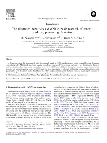
bistable or multivibratorFigure 8--1Two versions of SET-RESET (S-R) latches. Open file F08-01 and verify the operation of both latches.Thomas L. FloydDigital Fundamentals, 8eCopyright 2003 by Pearson Education, Inc.Upper Saddle River, New Jersey 07458All rights reserved.
Figure 8--2Negative-OR equivalent of the NAND gate S-R latch in Figure 8-1(b).Thomas L. FloydDigital Fundamentals, 8eCopyright 2003 by Pearson Education, Inc.Upper Saddle River, New Jersey 07458All rights reserved.
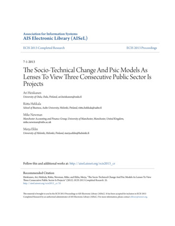
Figure 8--3The three modes of basic S-R latch operation (SET, RESET, no-change) and the invalid condition.
Figure 8--4Logic symbols for the S-R and S-R latch.Thomas L. FloydDigital Fundamentals, 8eCopyright 2003 by Pearson Education, Inc.Upper Saddle River, New Jersey 07458All rights reserved.
Figure 8—5 Example: Draw the waveform in the following situationThomas L. FloydDigital Fundamentals, 8eCopyright 2003 by Pearson Education, Inc.Upper Saddle River, New Jersey 07458All rights reserved.
Figure 8--6The S-R latch used to eliminate switch contact bounce.Thomas L. FloydDigital Fundamentals, 8eCopyright 2003 by Pearson Education, Inc.Upper Saddle River, New Jersey 07458All rights reserved.
Figure 8--7The 74LS279 quad S-R latch.Thomas L. FloydDigital Fundamentals, 8eCopyright 2003 by Pearson Education, Inc.Upper Saddle River, New Jersey 07458All rights reserved.
Figure 8--8A gated S-R latch.EN enableThomas L. FloydDigital Fundamentals, 8eCopyright 2003 by Pearson Education, Inc.Upper Saddle River, New Jersey 07458All rights reserved.
Figure 8-9 Example: Determine the waveform!Thomas L. FloydDigital Fundamentals, 8eCopyright 2003 by Pearson Education, Inc.Upper Saddle River, New Jersey 07458All rights reserved.
Figure 8--10A gated D latch.D dataThomas L. FloydDigital Fundamentals, 8eCopyright 2003 by Pearson Education, Inc.Upper Saddle River, New Jersey 07458All rights reserved.
Figure 8-11 Example: Determine the waveform!Thomas L. FloydDigital Fundamentals, 8eCopyright 2003 by Pearson Education, Inc.Upper Saddle River, New Jersey 07458All rights reserved.
Figure 8--12The 74LS75 quad gated D latches.Thomas L. FloydDigital Fundamentals, 8eCopyright 2003 by Pearson Education, Inc.Upper Saddle River, New Jersey 07458All rights reserved.
Figure 8--13Edge-triggered flip-flop logic symbols (top: positive edge-triggered; bottom: negative edge-triggered).Thomas L. FloydDigital Fundamentals, 8eCopyright 2003 by Pearson Education, Inc.Upper Saddle River, New Jersey 07458All rights reserved.
Figure 8--14Operation of a positive edge-triggered S-R flip-flop.
Figure 8-15, 8-16 Example: Determine the waveforms
Figure 8--17Edge triggering.Thomas L. FloydDigital Fundamentals, 8eCopyright 2003 by Pearson Education, Inc.Upper Saddle River, New Jersey 07458All rights reserved.
Figure 8--18Flip-flop making a transition from the RESET state to the SET state on the positive-going edge of the clock pulse.Thomas L. FloydDigital Fundamentals, 8eCopyright 2003 by Pearson Education, Inc.Upper Saddle River, New Jersey 07458All rights reserved.
Figure 8--19Flip-flop making a transition from the SET state to the RESET state on the positive-going edge of the clock pulse.Thomas L. FloydDigital Fundamentals, 8eCopyright 2003 by Pearson Education, Inc.Upper Saddle River, New Jersey 07458All rights reserved.
Figure 8--20A positive edge-triggered D flip-flop formed with an S-R flip-flop and an inverter.
Figure 8-21 Example: Determine the waveform!Thomas L. FloydDigital Fundamentals, 8eCopyright 2003 by Pearson Education, Inc.Upper Saddle River, New Jersey 07458All rights reserved.
Figure 8--22A simplified logic diagram for a positive edge-triggered J-K flip-flop.Thomas L. FloydDigital Fundamentals, 8eCopyright 2003 by Pearson Education, Inc.Upper Saddle River, New Jersey 07458All rights reserved.
Figure 8--23Transitions illustrating the toggle operation when J 1 and K 1.Thomas L. FloydDigital Fundamentals, 8eCopyright 2003 by Pearson Education, Inc.Upper Saddle River, New Jersey 07458All rights reserved.
Figure 8-24 Example: determine the Q output!Thomas L. FloydDigital Fundamentals, 8eCopyright 2003 by Pearson Education, Inc.Upper Saddle River, New Jersey 07458All rights reserved.
Figure 8-25 Example: Determine the Q!Thomas L. FloydDigital Fundamentals, 8eCopyright 2003 by Pearson Education, Inc.Upper Saddle River, New Jersey 07458All rights reserved.
Figure 8--26Logic symbol for a J-K flip-flop with active-LOW preset and clear inputs.Thomas L. FloydDigital Fundamentals, 8eCopyright 2003 by Pearson Education, Inc.Upper Saddle River, New Jersey 07458All rights reserved.
Figure 8--27Logic diagram for a basic J-K flip-flop with active-LOW preset and clear inputs.Thomas L. FloydDigital Fundamentals, 8eCopyright 2003 by Pearson Education, Inc.Upper Saddle River, New Jersey 07458All rights reserved.
Figure 8-28 Example: Determine the Q waveformOpen file F08-28 to verify the operation.Thomas L. FloydDigital Fundamentals, 8eCopyright 2003 by Pearson Education, Inc.Upper Saddle River, New Jersey 07458All rights reserved.
Figure 8--29Logic symbols for the 74AHC74 dual positive edge-triggered D flip-flops.Thomas L. FloydDigital Fundamentals, 8eCopyright 2003 by Pearson Education, Inc.Upper Saddle River, New Jersey 07458All rights reserved.
Figure 8--30Logic symbols for the 74HC112 dual negative edge-triggered J-K flip-flops.Thomas L. FloydDigital Fundamentals, 8eCopyright 2003 by Pearson Education, Inc.Upper Saddle River, New Jersey 07458All rights reserved.
Figure 8-31 Example: determine the 1Q waveform
Figure 8--32Basic logic diagram for a master-slave J-K flip-flop.Thomas L. FloydDigital Fundamentals, 8eCopyright 2003 by Pearson Education, Inc.Upper Saddle River, New Jersey 07458All rights reserved.
Figure 8--33Pulse-triggered (master-slave) J-K flip-flop logic symbols.Thomas L. FloydDigital Fundamentals, 8eCopyright 2003 by Pearson Education, Inc.Upper Saddle River, New Jersey 07458All rights reserved.
Figure 8-34 Example: determine the QThomas L. FloydDigital Fundamentals, 8eCopyright 2003 by Pearson Education, Inc.Upper Saddle River, New Jersey 07458All rights reserved.
Operating characteristicsFigure 8--35Propagation delays, clock to output.Thomas L. FloydDigital Fundamentals, 8eCopyright 2003 by Pearson Education, Inc.Upper Saddle River, New Jersey 07458All rights reserved.
Figure 8--36Propagation delays, preset input to output and clear input to output.Thomas L. FloydDigital Fundamentals, 8eCopyright 2003 by Pearson Education, Inc.Upper Saddle River, New Jersey 07458All rights reserved.
Figure 8--37 Set-up time (ts). The logic level must be present on the D input for a time equal to or greater than ts before the triggeringedge of the clock pulse for reliable data entry.Thomas L. FloydDigital Fundamentals, 8eCopyright 2003 by Pearson Education, Inc.Upper Saddle River, New Jersey 07458All rights reserved.
Figure 8--38 Hold time (th). The logic level must remain on the D input for a time equal to or greater than th after the triggering edge ofthe clock pulse for reliable data entry.Thomas L. FloydDigital Fundamentals, 8eCopyright 2003 by Pearson Education, Inc.Upper Saddle River, New Jersey 07458All rights reserved.
Hands on tip (page 417)CMOS can operate over wide power supply rangetyp. 2V to 6V. Therefore less expensive suppliescan be used (compared to TTL). Smaller supplyvoltage means less power dissipation. Downsideis the performance dependency on the supply voltage!
Figure 8--39Example of flip-flops used in a basic register for parallel data storage.Thomas L. FloydDigital Fundamentals, 8eCopyright 2003 by Pearson Education, Inc.Upper Saddle River, New Jersey 07458All rights reserved.
Figure 8--40The J-K flip-flop as a divide-by-2 device. Q is one-half the frequency of CLK.How do you createthe same action witha D –flip-flop?Thomas L. FloydDigital Fundamentals, 8eCopyright 2003 by Pearson Education, Inc.Upper Saddle River, New Jersey 07458All rights reserved.
Figure 8--41CLK.Example of two J-K flip-flops used to divide the clock frequency by 4. QA is one-half and QB is one-fourth the frequency ofThomas L. FloydDigital Fundamentals, 8eCopyright 2003 by Pearson Education, Inc.Upper Saddle River, New Jersey 07458All rights reserved.
Figure 8-42 Example 8-11: Develop the output waveform fout
Figure 8--44Flip-flops used to generate a binary count sequence. Two repetitions (00, 01, 10, 11) are shown.Thomas L. FloydDigital Fundamentals, 8eCopyright 2003 by Pearson Education, Inc.Upper Saddle River, New Jersey 07458All rights reserved.
Figure 8-45 Example 8-12: Determine the output waveforms
Figure 8--47A simple one-shot circuit.Check out the simulationThomas L. FloydDigital Fundamentals, 8eCopyright 2003 by Pearson Education, Inc.Upper Saddle River, New Jersey 07458All rights reserved.
Figure 8--48Basic one-shot logic symbols. CX and RX stand for external components.X stands forexternalcomponentsThomas L. FloydDigital Fundamentals, 8eCopyright 2003 by Pearson Education, Inc.Upper Saddle River, New Jersey 07458All rights reserved.
Figure 8--49Nonretriggerable one-shot action.Thomas L. FloydDigital Fundamentals, 8eCopyright 2003 by Pearson Education, Inc.Upper Saddle River, New Jersey 07458All rights reserved.
Figure 8--50Retriggerable one-shot action.Thomas L. FloydDigital Fundamentals, 8eCopyright 2003 by Pearson Education, Inc.Upper Saddle River, New Jersey 07458All rights reserved.
Figure 8--51Logic symbols for the 74121 nonretriggerable one-shot.Thomas L. FloydDigital Fundamentals, 8eCopyright 2003 by Pearson Education, Inc.Upper Saddle River, New Jersey 07458All rights reserved.
Figure 8--52Three ways to set the pulse width of a 74121.Thomas L. FloydDigital Fundamentals, 8eCopyright 2003 by Pearson Education, Inc.Upper Saddle River, New Jersey 07458All rights reserved.
Figure 8--53Logic symbol for the 74LS122 retriggerable one-shot.Thomas L. FloydDigital Fundamentals, 8eCopyright 2003 by Pearson Education, Inc.Upper Saddle River, New Jersey 07458All rights reserved.
Figure 8-54 Example: Create a oneshot with a pulse duration of 100 ms.µtW 0.7 REXT C EXTC EXTThomas L. FloydDigital Fundamentals, 8etW108 ns 3.66 10 6 pF 3.66 µF0.7 REXT 0.7 39kΩCopyright 2003 by Pearson Education, Inc.Upper Saddle River, New Jersey 07458All rights reserved.
Application exampleFigure 8--55A sequential timing circuit using three 74LS122 one-shots.Thomas L. FloydDigital Fundamentals, 8eCopyright 2003 by Pearson Education, Inc.Upper Saddle River, New Jersey 07458All rights reserved.
Application example for a oneshotActive fuseinstantenous current spike (over current) initiates a pulsewhich is used to inhibit the current in some vital part of thecircuit. The power is restored after the pulse goes low.
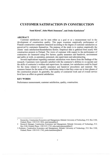
Figure 8--56Internal functional diagram of a 555 timer (pin numbers are in parenthesis).Thomas L. FloydDigital Fundamentals, 8e
Figure 8--57The 555 timer connected as a one-shot.tW 1.1R1C1µThomas L. FloydDigital Fundamentals, 8eCopyright 2003 by Pearson Education, Inc.Upper Saddle River, New Jersey 07458All rights reserved.
Figure 8--58One-shot operation of the 555 timer.
Figure 8--59The 555 timer connected as an astablemultivibrator (oscillator).µThomas L. FloydDigital Fundamentals, 8eCopyright 2003 by Pearson Education, Inc.Upper Saddle River, New Jersey 07458All rights reserved.
Figure 8--60Operation of the 555 timer in the astable mode.Thomas L. FloydDigital Fundamentals, 8eCopyright 2003 by Pearson Education, Inc.Upper Saddle River, New Jersey 07458All rights reserved.
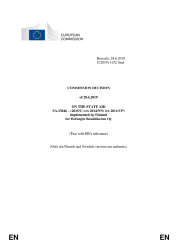
Figure 8--61Frequency of oscillation as a function of C1 and R1 1 2R2. The sloped lines are values of R1 1 2R2.1.44f ( R1 2 R2 )C1f Thomas L. FloydDigital Fundamentals, 8e1.44( R1 2 R2 )C1 R1 R2 100%Duty cycle R1 2 R2 Copyright 2003 by Pearson Education, Inc.Upper Saddle River, New Jersey 07458All rights reserved.
Figure 8--62The addition of diode D1 allows the duty cycle of the output to be adjusted to less than 50 percent by making R1 R2.µFThomas L. FloydDigital Fundamentals, 8e R1 100%Duty cycle R1 R2 Copyright 2003 by Pearson Education, Inc.Upper Saddle River, New Jersey 07458All rights reserved.
Figure 8-63 Example 8-16: Determine the frequency and the duty cycle (Open file F08-63 to verify operation).Solution5.64kHz59.5%µThomas L. FloydDigital Fundamentals, 8eµCopyright 2003 by Pearson Education, Inc.Upper Saddle River, New Jersey 07458All rights reserved.
Figure 8--64Two-phase clock generator with ideal waveforms. Open file F08-64 and verify the operation.Thomas L. FloydDigital Fundamentals, 8eCopyright 2003 by Pearson Education, Inc.Upper Saddle River, New Jersey 07458All rights reserved.
Figure 8--65Logic analyzer displays for the circuit in Figure 8-64.glitchesThomas L. FloydDigital Fundamentals, 8eCopyright 2003 by Pearson Education, Inc.Upper Saddle River, New Jersey 07458All rights reserved.
Figure 8--66 Two-phase clock generator using negative edge-triggered flip-flop to eliminatethe operation.Thomas L. FloydDigital Fundamentals, 8eglitches. Open file F08-66 and verifyCopyright 2003 by Pearson Education, Inc.Upper Saddle River, New Jersey 07458All rights reserved.
Hands on TipThe glitches are usually very fast, short in duration signals andcan be diffucult to see on an oscilloscope. Logic analyzer arebetter suited for detecting glitches. Select latch mode or transitional sampling.
Figure 8--67GAL block diagrams.
Figure 8--68The GAL22V10 OLMC.Thomas L. FloydDigital Fundamentals, 8eCopyright 2003 by Pearson Education, Inc.Upper Saddle River, New Jersey 07458All rights reserved.
Figure 8--69The GAL16V8 OLMC.Thomas L. FloydDigital Fundamentals, 8eEmulation of most of the existing PALsCopyright 2003 by Pearson Education, Inc.Upper Saddle River, New Jersey 07458All rights reserved.
Figure 8--70Traffic light control system block diagram.Thomas L. FloydDigital Fundamentals, 8eCopyright 2003 by Pearson Education, Inc.Upper Saddle River, New Jersey 07458All rights reserved.
Figure 8--71Block diagram of the timing circuits.Thomas L. FloydDigital Fundamentals, 8eCopyright 2003 by Pearson Education, Inc.Upper Saddle River, New Jersey 07458All rights reserved.
Figure 8--72
Figure 8--73
Figure 8--74Thomas L. FloydDigital Fundamentals, 8eSUMMARYCopyright 2003 by Pearson Education, Inc.Upper Saddle River, New Jersey 07458All rights reserved.
Objectives Use logic gates to construct basic latches Explain the difference between an S-R latch and a D latch Recognize the difference between a latch and a flip-flop