Transcription
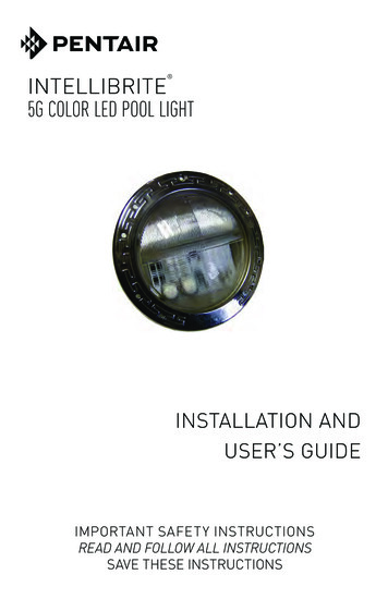
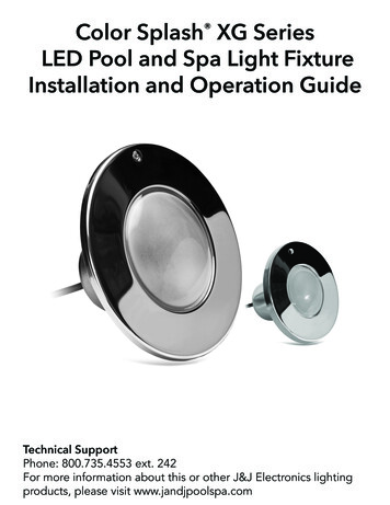
GLOBRITE COLOR CHANGING LED LIGHTFOR POOL AND SPAINSTALLATIONANDUSER’S GUIDEIMPORTANT SAFETY INSTRUCTIONSREAD AND FOLLOW ALL INSTRUCTIONSSAVE THESE INSTRUCTIONSGLOBRITE Underwater Color Changing LED Pool/Spa Light Installation and User’s Guide
Technical SupportPhone: (800) 831-7133 - Fax: (800) 284-4151Web sites: www.pentairpool.com and www.staritepool.com:ContentsIMPORTANT WARNING AND SAFETY INSTRUCTIONS. i-iiGloBrite Color Changing LED Pool Light Overview. 1Operating GloBrite Color Lights Using a Wall Switch . 1Operating GloBrite Color Lights Using Automation Control System . 1Using an External (12 VAC)Transformer for Multiple GloBrite Color Lights . 1Operating GloBrite Color Lights Using a Wall Switch . 2Powering on the GloBrite Lights . 2Selecting a GloBrite Light Show Modes or Fixed Colorusing a Wall Switch . 2Saving a Color Mode or Fixed Color . 3Selecting a GloBrite Light Color and Show Modes or Fixed Color Usingan Intellibrite Controller . 3GloBrite Color Light Fixture Installation (new pool construction) . 4Installing the GloBrite Color Light Sleeve and Niche (After ElectricalRequirements are Met). 4Installing GloBrite Color Light Sleeve & NIche in a Concrete/Gunite Pool. 5Option 1: Niche Sleeve with Cone Installation Diagram. 5Option 2: Conduit to Niche. 6Installing GloBrite Color Light Niche in a Fiberglass Pool. 7Installing GloBrite Color Light Niche in a Vinyl Pool. 8Installing The GloBrite Color Light Assembly (After Niche Installation). 9GloBrite Color Light Installation/Removal Tool .1 0Replacing the GloBrite Color Light Assembly (in an ExistingPool or SPA) . 11Replacing the GloBrite Color Light Assembly (After ElectricalRequirements are Met) . 12Connecting GloBrite Lights to EasyTouch or IntelliTouch ControlSystem Load Center. 13EasyTouch and IntelliTouch Control System Load Center Wiring Diagr a m . 14Setting up GloBrite Color Lights with EasyTouch/IntelliTouch Control System. 15IntelliTouch Control System. . 16Set up a GloBrite Color Light.Circuit Function . 17Wiring Globrite Color Lights to IntelliBrite Controller and 300 Watt Transformer. 18Troubleshooting (GloBrite Color Lights).19Troubleshooting (IntelliBrite Controller).19GloBrite Color Lights Parts List and Replacement Kits . 19GloBrite Lights. 19GloBrite Bundles. 19GloBrite Color Light Niches. 20GloBrite Color Light Replacement Kits. 20READ AND FOLLOW ALL INSTRUCTIONS IN THIS MANUAL.GLOBRITE Color Changing LED Pool /Spa Light Installation and User’s Guide
iIMPORTANT WARNING AND SAFETY INSTRUCTIONSSERIOUS BODILY INJURY OR DEATH CAN RESULT IF THIS LIGHTIS NOT INSTALLED AND USED CORRECTLY.INSTALLERS, POOL OPERATORS AND POOL OWNERS MUSTREAD THESE WARNINGS AND ALL INSTRUCTIONS BEFOREUSING THE POOL AND/OR SPA LIGHT.Most states and local codes regulate the construction, installation, andoperation of public pools and spas, and the construction of residentialpools and spas. It is important to comply with these codes, many of which directlyregulate the installation and use of this product. Consult your local building and healthcodes for more information.IMPORTANT NOTICE - Attention Installer: This Installation and User’sGuide (“Guide”) contains important information about the installation,operation and safe use of this underwater pool and spa light. This Guideshould be given to the owner and/or operator of this equipment.Before installing this product, read and follow all warning noticesand instructions in this Guide. Failure to follow warnings andinstructions can result in severe injury, death, or property damage.Call (800) 831-7133 for additional free copies of these instructions. Please refer towww.pentairpool.com for more information related to this products.RISK OF ELECTRICAL SHOCK OR ELECTROCUTION:THE GLOBRITE LIGHT REQUIRES HIGH VOLTAGE WHICH CANSHOCK, BURN, OR CAUSE DEATH.BEFORE WORKING ON the GloBrite Color light alwaysdisconnect power to the pool and/or spa lights at the sourcecircuit breaker from the light before servicing the light. Failureto do so could result in death or serious injury to serviceperson, pool users or others due to electric shock. Wheninstalling and using this electrical equipment, basic safetyprecautions should always be followed, include the following:This underwater light must be installed by a licensed or certified electrician or aqualified pool professional in accordance with the current National Electrical Code(NEC), NFPA 70 or the Canadian Electrical Code (CEC), CSA C22.1. All applicablelocal installation codes and ordinances must also be adhered to. Improperinstallation will create an electrical hazard which could result in death or seriousinjury to pool users, installers or others due to electrical shock, and may also causedamage to power source. Always disconnect the power to the pool light at the circuitbreaker before servicing the light. Failure to do so could result in death or seriousinjury to service person, pool users or others due to electrical shock.For countries in compliance with International ElectrotechnicalCommission (IEC) regulatory standards: The light fixture must beinstalled by a licensed or certified electrician or a qualified pool service person, inaccordance with current IEC 364-7-702 and all applicable local codes and ordinance.Improper installation will create an electrical hazard, which could result in death orserious injury to pool user, installer or other due to electrical shock and may also causedamage to the property.GLOBRITE Color Changing LED Pool/Spa Light Installation and User’s Guide
iiIMPORTANT WARNING AND SAFETY INSTRUCTIONSRisk of Electrical Shock. Connect only to a branch circuitprotected by a ground-fault circuit-interrupter (GFCI). Contact a qualifiedelectrician if you cannot verify that the circuit is protected by a GFCI.This light must be connected only to a supply circuit that is protected by a ground-faultcircuit-interrupter (GFCI). Such a GFCI should be provided by the installer and shouldbe tested on a routine basis. To test the GFCI, push the test button. The GFCI shouldinterrupt power. Push the reset button. Power should be restored. If the GFCI fails tooperate in this manner, the GFCI is defective. If the GFCI interrupts power to the lightwithout the test button being pushed, a ground current is following, indicating thepossibility of an electric shock. Do not use this light. Disconnect the light and have theproblem corrected by a qualified service representative before using.Locate your pool so that the wall is at least 10 feet (3.048 m) from all electricalreceptacles and at least 20 feet (6.1 m) from all receptacles not protected by a GFCI. Itis also very important to locate the pool so that it is not under any electrical wiring, thatis less than 18 feet (5.49 m) vertically above the pool wall and within an area located10 feet outside the pool walls. The pool must also never be located under any lightingfixture or within five (5) feet (1.5 m) measured horizontally from any fixture mountedless than five (5) feet (1.5 m) vertically above the pool water level.NOTICE: The external flexible cable or cord of this luminaire cannot be replaced; ifthe cord is damaged, the luminaire shall be destroyed.For countries in compliance with International ElectromechnicalCommission (IEC) regulatory standards: The light fixture must beinstalled by a licensed or certified electrician or a qualified pool service person, inaccordance with IEC 364-7-702 and all applicable local codes and ordinance. Improperinstallation will create an electrical hazard, which could result in death or serious injuryto pool user, installer or other due to electrical shock and may also cause damage to theproperty.INSTALLERS AND INSPECTORSTHE GLOBRITE COLOR LIGHT AND PLASTIC NICHE FORM A COMPLETENON-METALLIC LOW VOLTAGE LIGHTING SYSTEM. THIS CONFIGURATION DOESNOT REQUIRE BONDING OR GROUNDING WHEN POWERED BY A LISTED 100WATT OR 300 WATT TRANSFORMER (LISTED ON PAGE 20) AND INSTALLED INCOMPLIANCE WITH THE CURRENT NATIONAL ELECTRIC CODE (NEC).UNBONDED LIGHTING NEC PROVISIONSWhen the UL listed non-metallic GloBrite color light low voltage lights are usedwith the GloBrite light approved niches (as listed on page 20), the current NECprovides an exception to luminaire bonding and grounding in Article 680.6 and680.23POOL WATER BONDING NEC PROVISIONSFor Pool Water Bonding required by NEC Article 680.26C, concrete pools areconsidered conductive (refer to 680.26 (b)(1) due to the porosity of concrete andthe bonding of rebar. No additional bonding is required.GLOBRITE Color Changing LED Pool /Spa Light Installation and User’s Guide
1GloBrite Color Changing LED Pool Light OverviewThis manual describes how to install and replace the GloBrite underwater colorchanging LED light for pool and spa. GloBrite color lights provides brilliant vivid multicolors with spectacular effects for your pool. The energy efficient colored array utilizesIntelliBrite color light technology and can cycle through colors at varying speeds and indifferent sequences of color. Choose one of the seven pre-programmed color light showsor select one of the five fixed colors to create virtually endless range of dramaticunderwater lighting effects for a spectacular effect in your pool and spa.Operating GloBrite Color Lights Using a Wall SwitchThe GloBrite light can be manually controlled using a standard wall-mount light switch.Multiple GloBrite lights can be connected via a junction box and a 12 VAC transfomer to.a single switch so that all lights can be switched on and off together.For wiring diagramsee. page 14.Operating GloBrite Color Lights Using Automation Control SystemGloBrite lights can also be automatically controlled using the Pentair IntelliTouch Control System and the EasyTouch Control System (see page 14). For moreinformation refer to the IntelliTouch Control System User’s Guide (P/N 521075),EasyTouch Control System User’s Guide (P/N 521044), and SunTouch Control SystemUser’s Guide (P/N 520785).Using one (12 VAC) transformer for Multiple GlorBrite LightsWhen using multiple GloBrite lights on a 100 Watt ( 12VAC ) transformer, it isrecommended that no more than three (3) GloBrite lights be used. For long cablelenghts with a single light, It is recommended not to exceed 100 feet (30.48 m) of totalcable run between the transformer and light.100 WattTransformer12 Gauge(minimum)J Box100 ft.Note: If a longer cable runis necessary, it isrecommended thatseparate 100 Watt/12 VACtransformers be used foreach light with no morethan 100 feet of totalcable run between thetransformer and lights.GLOBRITE Color Changing LED Pool/Spa Light Installation and User’s Guide
2Operating GloBrite Color Lights Using a Wall SwitchGloBrite color lights can be controlled using a standard wall-mount light switch or bythe IntelliBrite color light controller (see page 3). Multiple GloBrite lights can be connected via a junction box and 12 VAC transformer to a single switch so that all lightscan be switched on and off together. GloBrite lights are controlled by cycling AC powerto the 12 VAC transformer from a standard wall switch. By turning the switch on andoff a specific number of times, the light activates one of the seven ligt show modes, fixedcolors, or enables the “Hold” and “Recall” feature.Powering on the GloBrite LightsWhen the GloBrite light is powered on, goes to the previously selected mode or colorNote: If power to the light is off for more than five (5) seconds, the last color show modeor fixed color that was saved will be displayed.Note: When the GloBrite light(s) are powered on, it will go to the selectedcolor, unless the HOLD or RECALL feature was previously enabled.Selecting a GloBrite Light Show Mode or Fixed Color using aWall SwitchGloBrite color lights are compatible with IntelliBrite light colors and shows and can besynchronized with IntelliBrite color lights.Number of times to cycle power (1-14)First switch power on to the light. The light will go to the previously selected color. Toselect a color show mode (1-7) or fixed color (8-12), turn the wall switch off/on aspecific number of times. Each number (1-12) shown below corresponds to the numberof times to power-cycle the switch to activate a color light show or fixed color. Fordetails about saving color effects while in “show” modes, see “Hold” and “Recall”feature on page 3.1234567891011121314SAm Mode: Cycles through white, magenta, blue and green colors(emulates the Pentair SAm color changing light).Party Mode: Rapid color changing building energy and excitement.Romance Mode: Slow color transitions creating a mesmerizing andcalming effect.Caribbean Mode: Transitions between a variety of blues and greens.American Mode: Patriotic red, white and blue transition.California Sunset Mode: Dramatic transitions of orange, red andmagenta tones.Royal Mode: Richer, deeper color tones.Blue: Fixed color.Green: Fixed color.Red: Fixed color.White: Fixed color.Magenta: Fixed color.Hold: Save the current color effect during a color light show.Recall: Activate the last saved color effect.GLOBRITE Color Changing LED Pool /Spa Light Installation and User’s Guide
3Example: To select California Sunset Mode; turn the switch off and on six (6) successivetimes. During the off/on switching process, no illumination will occur. At the next power up,the light will come on in California Mode.During the off/on switching process, before theselected color is displayed, no illumination will occur.This operating mode is normal during the switching process. During thisperiod the pool and spa will be dark and precautions should be taken toavoid unforeseen accidents. Failure to observe this warning may resultin serious injury or death to pool and spa users.Saving a Color Mode or Fixed ColorWhen power is switched off to the GloBrite color lights, the last color show mode orfixed color will be saved. The next time the light is powered on, the previously savedcolor show mode or fixed color will be displayed. For example, while in “Party Mode”switch the light off. Wait more than 10 seconds, switch the light back on to resume “PartyMode.”Selecting a GloBrite Light Color and Show Modes or FixedColor Using an IntelliBrite ControllerInstead of using a wall switch, GloBrite lights can becontrolled with the IntelliBrite Controller (p/n600054, sold separately). The IntelliBrite Controllerprovides complete control of your GloBrite lights. It’seasy to select a lighting feature, just dial in any oneof the pre-programmed color light shows or fixedcolors. Using the Hold and Recall buttons you canalso create endless unique lighting effects. TheIntelliBrite Controller can control individual ormultiple 12 VAC transformers to controlGloBrite lights.Note: For IntelliBrite controller wiring instructions, see page 14.Using the IntelliBrite Color Light Controller: GloBrite lights are compatible withIntelliBrite colors and shows and can be synchronized with IntelliBrite color pool/spa andlandscape lights. To select a color light show mode or fixed color mode, rotate the dial sothat it points to the desired selection. The color mode selections start in a clockwisedirection from the 9 o’clock position.Hold and Recall FeatureHold button/LED: Press this button (LED on) to capture and save a color effect whiledisplaying one of the light show modes. When the button is pressed, the LED will be on,indicating that the color effect is captured.Recall Button/LED: Use this button (LED on) to activate the last saved color effect. Whenthe button is pressed, the LED will be on, indicating that the color effect is beingdisplayed.GLOBRITE Color Changing LED Pool/Spa Light Installation and User’s Guide
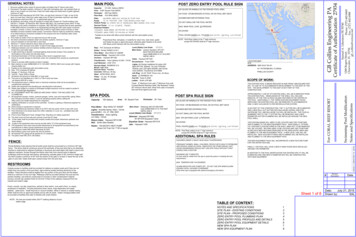
4GLOBRITE COLOR LIGHT FIXTURE INSTALLATION(NEW POOL CONSTRUCTION)The following describes how to install the GloBrite color light fixture.BEFORE STARTING: The following information describes the tasks that mustbe completed by the electrician before the light fixture is installed. SeeFigure 1 on page 7.Be sure that the pool or spa meets the requirements of the current National ElectricalCode (N.E.C.) Article 680-22 and all local codes and ordinances. A licensed orcertified electrician must install the electrical system to meet or exceed thoserequirements before the underwater light is installed. Some of the requirements ofthe National Electrical Code which the pool’s electrical system must meet are asfollows: The Junction Box and the low voltage transformer is located at leasteight (8) inches (20.3 cm) above ground level and at least 48 inches(1.22 m) from the edge of the pool. See Figure 1 on page 7. The GloBrite light niche must be properly installed so that the top edgeof the GloBrite light’s lens is at least 4 inches below (not more than 48inches below in Canada) the surface of the water in the pool or spa. To be certain that the pool or spa electrical system meets all applicablerequirements, the electrician should also consult the local buildingdepartment.INSTALLING THE GLOBRITE C O L O R LIGHT SLEEVE AND NICHE(AFTER ELECTRICAL REQUIREMENTS ARE MET)The GloBrite light niche can be installed in concrete/gunite, fiberglass or vinyl pools.Note: GloBrite light niche must be installed in or on the wall of the pool (or waterfeature) with the top of the lens not less than 4 inches (10.2 cm) below the normalwater level of the pool.GLOBRITE Color Changing LED Pool /Spa Light Installation and User’s Guide
5 Installing GloBrite Color Light Sleeve & Niche in aConcrete/Gunite PoolOption 1: Niche Sleeve with Cone. Installation Diagram(Cone is used for applications where the niche is installed after the conduit has been connected to the 2” sleeve).2” PVC pipe Schedule 40(Niche Sleeve)2” to 1” reducer11” Min.Cone1” Conduit glue to reducerColor RingGunite nicheGunite Cover1.Install Sleeve: Locate position on pool or spa wall where light is tobe installed. The top of the light lens must be a minimum of four (4) inchesbelow normal water level. Refer to Figure 1 on page 7 for the exact depthrequirements.2.Install a 2 inch (5 cm) PVC pipe schedule 40 (15“ minimum (38.1cm) long)in the desired location for the light.3.Allow at least 1 inch (2.5 cm) of the niche sleeve (2 inch (5 cm) PVC pipe)to stick out on the pool side of the wall during your gunite operation, and cutany excess pipe flush to the Gunite wall before installing niche.Glue a 2” x 1” reducer bushing to the back side of the niche sleeve.Glue 1” conduit into reducer as shown on option 1. Make sure the 2” PVCpipe Schedule 40 accomodates for the total length of niche/cone & reducerassembly.Glue cone into gunite niche (The cone is used to guide the fish tape from thethe junction box into the niche).Apply PVC cement inside of the sleeve and slide the gunite niche into thesleeve until it is flush to the gunite wall.4.5.6.7.8.9.10.11.12.13.Add the desired color ring to the front of the niche.If required by local code install GloBrite light into niche follow steps on page 9.Cover front end of niche by snapping gunite cover over the front. This willprotect the cooling cavity of the niche during plastering.If a gunite cover is not available, use masking tape to protect lens andcooling cavity from plaster operation.Apply plaster to pool wall up to the outer edge of the gunite cover (gunitecover should be the only exposed part of the niche after plastering).Once plastering is completed, remove and dispose gunite cover.GLOBRITE Color Changing LED Pool/Spa Light Installation and User’s Guide
6Option 2: Conduit to Niche2” PVC pipe Schedule 40(Niche Sleeve)Color Ring11” MinimumGunite niche1” Conduit glueto Gunite Niche1.2.3.4.5.6.7.8.9.10.11.12.Gunite CoverInstall Sleeve: Locate position on pool or spa wall where light is tobe installed. The top of the light lens must be a minimum of four (4) inchesbelow normal water level. Refer to Figure 1 on page 7 for the exact depthrequirements.Install a 2 inch (5 cm) PVC pipe schedule 40 (15” minimum (38.1cm) long)in the desired location for the light.Allow at least 1 inch (2.5 cm) of the niche sleeve 2 inch (5 cm) PVC pipeto stick out on pool side of the wall during your gunite operation, and cutany excess of pipe flush to the Gunite wall before installing niche.Fish 1”conduit through the 2” PVC sleeve schedule 40.Glue 1” conduit into back of niche as shown on option 2.Apply PVC cement inside of the sleeve and slide the gunite niche intothe sleeve until it is flush to the wall.Add the desired color ring to the front of the gunite niche.If required by local code install GloBrite light into niche follow steps on page 9.Cover front end of niche by snapping plaster cover over the front. This willprotect the cooling cavity of the niche during plastering.If a gunite cover is not available,use masking tape to protect lens andcooling cavity from plaster operation.Apply plaster to pool wall up to the outer edge of the gunite cover (gunitecover should be the only exposed part of the niche after plastering).Once plastering is completed, remove and dispose gunite cover.GLOBRITE Color Changing LED Pool/Spa Light Installation and User’s Guide
7To 12 VACTransformer8” (20.3 cm)48” (1.22 m)min.18” (46 cm) minimum4” min. (10.2 cm)to top of lensRidgid1” (3 cm)ConduitNiche Sleeve: 2” PVC PipeFor Gunite Niche Only( 15” min.)( 35.1 cm )Niche Sleeve(cut flush to wallbefore plastering)Color Ring and Gunite CoverPlaster FinishFigure 1.Installing GloBrite Color Light Niche in a Fiberglass PoolTo install the GloBrite color light niche in a fiberglass pool:1.2.3.4.5.6.Drill or punch a 2” hole in the desired location for the GloBrite light niche(See Figure 1).Place the sealing gasket on the niche as seen in figure 2.Insert the niche through the 2” hole on the pool wall.Install the PVC washer to the back of the niche.Install the plastic nut onto the back of the niche.Tighten the nut to secure the niche in place.Glue 1” conduit into back of niche.Pool WallNicheFigure 2.1” ConduitNutPVC WasherSealing gasketGloBrite Light Niche (Fiberglass pool) Installation DiagramGLOBRITE Color Changing LED Pool /Spa Light Installation and User’s Guide
8Installing GloBrite Color Light Niche in a Vinyl Pool1.2.3.Drill a 3” hole in the desired location for the GloBrite light.Insert the Vinyl niche through the 3” hole from the inside of the pool.Install the plastic nut onto the back of the niche. Tighten the nut to securethe niche in place.4. Place the sealing gasket onto front of niche as seen on figure 3.5. Properly install liner.6. Carefully align the faceplate to the niche by using the alignment tabson the niche. Once the faceplate is properly aligned pierce liner throughfaceplate and install screws one at a time.7. Using a No. 2 Phillips head screwdriver, hand tighten each retaining screwto secure the cover. DO NOT OVER TIGHTEN THE SCREWS. DO NOTASSEMBLE WITH POWER TOOLS. Over tightening or using a motorizedscrewdriver on the sealing ring screws can over torque the screw threads anddamage the niche housing and /or liner seal.Wall panelLinerNiche1” ConduitFace PlateNutStainless steelsheet metalscrews (x4)Figure 3.Sealing GasketGloBrite Light Niche (Vinyl pool) Installation DiagramGLOBRITE Color Changing LED Pool /Spa Light Installation and User’s Guide
9INSTALLING THE GLOBRITE COLOR LIGHT ASSEMBLY(AFTER NICHE INSTALLATION)To install the GloBrite color light into the gunite, fiberglass or vinyl niche:1.Route the GloBrite cord through the front of the niche, to the location ofthe 12 VAC pool transformer or junction box.2.At the 12 VAC transformer or junction box, leave at least six (6) inches,(15.2 cm) of cord in the Junction Box or transformer to facilitate the lightinstallation and niche inspection, then cut off any extra cord.See Figure 1 on page 7.Strip back the outer cord jacket of the wires to expose the two (2) insulatedconductors. Strip back the two wires (be careful not to damage the copperconductor).3.4.Push the light into the niche while pulling the power cord from the junctionbox or transformer.Note: If you are using longer runs of cables or multiple lights pertransformer, it is recommended to use the 13 VAC or even the 14 VACtap on your transformer if available.Locking tabsLight niche(gunite nicheshown)Light power cordLightGloBrite Niche and LightGLOBRITE Color Changing LED Pool /Spa Light Installation and User’s Guide
105.Place the light installation tool (P/N 620057) over the front of the light. Turnthe tool and light clockwise while pushing inward, until you feel the stop point.This indicates the light is properly seated, locked and the electrical conduitis completely sealed.Note: If the light does not turn smoothly, pull the light slightly out and makesure that it’s seated properly and the niche is free of debris Then install thelight as described in step 5.Rotate handle clockwisetoo installor counter-clockwiseito removeLight installationand removal toolAlign and insert tool pins with holesinn front of light lens.6.Fill the pool until the light is completely submerged in waterbefore operating the light.Note: The GloBrite color light should not be powered for more than 30seconds if not submersed in water.7.Final check for proper GloBrite light operation: Switch on the main switchor circuit breaker to the 12 VAC transformer, and the switch that operatesthe GloBrite underwater light itself. The light should illuminate when 12 VACpower is applied. If not, recheck the installation steps.GLOBRITE Color Changing LED Pool /Spa Light Installation and User’s Guide
11REPLACING THE GLOBRITE COLOR LIGHT ASSEMBLY(IN AN EXISTING POOL OR SPA)Risk of Electrical Shock or Electrocution!This underwater light must be installed by a licensed or certifiedelectrician or a qualified pool professional in accordance withthe current National Electrical Code (NEC), NFPA 70 or theCanadian Electrical Code (CEC), CSA C22.1 and all applicablelocal codes and ordinances. Improper installation will create anelectrical hazard which could result in death or serious injury topool users, installers or others due to electrical shock, and mayalso cause damage to property.Always disconnect the power to the pool light at the circuitbreaker before servicing the light. Failure to do so could result indeath or serious injury to serviceman, pool users or others dueto electrical shock.Verify that the pool and spa meets the requirements of the current NationalElectrical Code and all local codes and ordinances. A licensed or certifiedelectrician must install the electrical system to meet or exceed thoserequirements before the underwater light is installed. Some of the requirementsof the National Electrical Code which the pool’s electrical system must meet areas follows: The Junction Box and the 12 VAC transformer is located at least eight(8) inches (20.3 cm) above ground level and at least 48 inches (1.22 m)from the edge of the pool. See Figure 1 on page 6. The GloBrite color light niche must be properly installed so that the topedge of the GloBrite light’s lens is at least 4 inches below (not more than 48inches below in Canada) the surface of the water in the pool or spa. To be certain that the pool or spa electrical system meets all applicablerequirements, the electrician should also consult the local buildingdepartment.GLOBRITE Color Changing LED Pool /Spa Light Installation and User’s Guide
12REPLACING THE GLOBRITE COLOR LIGHT ASSEMBLY(AFTER ELECTRICAL REQUIREMENTS ARE MET)The following removal and installation instructions describe how to remove and installthe GloBrite color light assembly.Failure to bring the pool or spa’s electrical system up to code requirementsbefore installing the underwater light will create an electrical hazard whichcould result in death or serious injury to pool users, installers, or others due toelectrical shock, and may also cause damage to property.1.Switch off electrical switch or circuit breaker at the source.2.Remove Junction Box or Transformer cover, disconnect the light wires andattach a fish tape to the existing light cable (this will assist in pulling thereplacement light cable through the conduit back to the junction box).Using the provided installation tool, rota
GloBrite color lights are compatible with IntelliBrite light colors and shows and can be synchronized with IntelliBrite color lights. First switch power on to the light. The light will go to the previously selected color. To select a color show mode (1-7) or fixed color (8-12)