Transcription
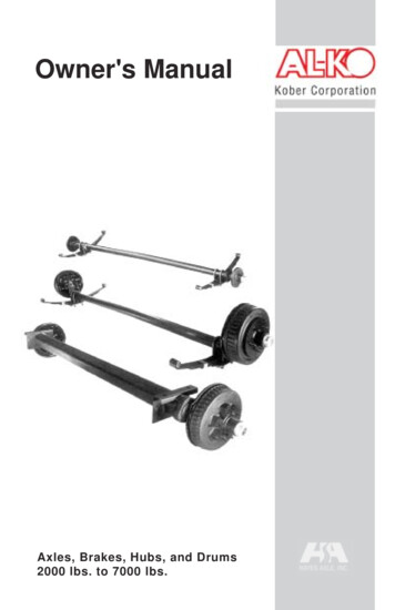
Owner's ManualAxles, Brakes, Hubs, and Drums2000 lbs. to 7000 lbs.1
12022
Table of ContentsIntroduction. 4Safety. 5Electric Brake Operation. 6-7Before The First Trip. 8-10General Maintenance. 11Storage Maintenance. 12Service Preparation. 13Brake Assemblies. 14-19Adjustment. 14Shoe & Lining. 15-16Magnet. 17-19Bearings, Races and Seals. 20-21Brake Drum. 22-23Completing Service. 24Tire Inspection. 25Troubleshooting. 26-29Suspension Components. 30-31Replacement Parts. 32-37Warranty. 40Approved3
IntroductionAL-KO Kober Corporation and Hayes Axle Inc. are major suppliers tothe light trailer industry. Our axles, brakes, hubs and drums are inoperation around the world, helping trailers tow smoothly and stopsafely. Our product line is the result of years of advanced engineeringin the United States as well as Germany, where vehicular technology isunsurpassed. AL-KO and Hayes products have undergone years ofexhaustive testing and we continue to strive for superior reliability,safety and performance.This manual contains information about axle assemblies, attachingparts, electric brakes and hub/drum assemblies.Leaf Spring Axle AssembliesAttaching Parts ForLeaf Spring AxlesRubber Torsion Axle AssemblyHub/Drum and Electric BrakeAdhering to the recommended service schedule on page 11 will ensurethe finest towing and stopping action available.4
ASafety FirstThis manual describes service and repair procedures for AL-KO Koberand Hayes Axle trailer axles. Technicians must follow their employer’sprocedures and these procedures when servicing or repairing equipmentor components. Before performing any service or maintenance, reviewthe trailer manufacturer’s recommendation for procedures and warnings.The service and maintenance procedures are provided for use byqualified service technicians. Do not attempt to service, repair orwork on brakes or axles unless you have appropriate mechanicalknowledge and skills. You must understand all procedures andinstructions before you begin to work on a unit. Some proceduresrequire the use of special tools for safe and correct service. Failureto use special tools when required can cause damage to equipmentand components. Lack of proper training, failure to follow properprocedures, or not using proper tools or safety equipment, canresult in property damage, serious personal injury, or loss of life.The following symbols are used to warn the user of potential dangersthat could cause serious damage to equipment or cause personal injuryor death.!WARNING This indicates a procedure that youmust follow exactly to avoid damaging equipment or componentsand to avoid serious personal injury, or loss of life.FASTENER TORQUEFasteners must be tightened to aspecific torque value. The technicianmust use the proper torque wrench to perform these operations.Improper torque can result in product failure which could causeproperty damage, serious injury, or loss of life.!WARNING!Current AL-KO and Hayes brake liningsare asbestos free. Other brake liningsmay contain asbestos fibers, a cancer and lung disease hazard.Many brake linings contain non-asbestos fibers, whose long-termeffects to health are unknown. You must use caution when youhandle both asbestos and non-asbestos materials. (See page 38.)ASBESTOS FIBER! WARNINGTo prevent serious eye injury, always wearsafety eye protection when you perform vehiclemaintenance or service.5
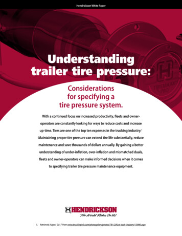
Electric Brake OperationAL-KO and Hayes electric brakes are cam actuated, self energizingdrum brakes. Their operation is similar to automotive drum brakes butthe actuation system is different. Electric brakes are actuatedelectrically through a magnet rather than hydraulically through a wheelcylinder. The magnet is positioned so its poles are close to an armaturesurface, which is machined or bolted inside the brake drum. When themagnet is energized, it is attracted to the armature surface causing africtional force that pivots the lever arm and slipper block. This forcesthe primary shoe against the drum which energizes the secondary shoe.(Visit www.al-kousa.com for animation.)Electric Brake Assembly(10" Left Hand Shown)Primary Shoe(Shorter Lining)Secondary ShoeSlipperBlockRetractSpringShoe HoldDownAssemblyLever ArmMagnetAdjusterScrewTrailer Front6
Typical Brake SystemAL-KO Kober and Hayes Axle supply electric brake assemblies asshown on the opposite page. Many components make up the entire“braking system”. Several components are not supplied by AL-KOKober or Hayes Axle including:Brake ControllerResistorsConnectorsBreak-away SwitchBatteryFusesWire Harness.The specific components on your braking system may vary at thediscretion of the trailer manufacturer or dealer. Below is a schematicshowing possible components and general c f this total system, AL-KO and Hayes supply the brake assemblies.Since proper function of your brakes depends on many components,please follow the vehicle or component manufacturer’srecommendations when installing, using or servicing these components.7
Before The First Trip1Adjust brakes after the first 200 miles and then asoutlined on page 11. A “green brake” is an unburnished brake.Normal manufacturing tolerances dictate that there is a break-inperiod required after which the lining will seat and become perfectlyconcentric with the drum. During this break-in period, the user mustbe aware that additional brake adjustments are mandatory to achieveoptimum braking performance.!WARNING Failure to adjust brakes can result inbrake lockup, reduced brake performance, or total loss of brakeswhich can lead to serious personal injury or loss of life.2Set the hitch or pin height of the tow vehicle so thatthe trailer is being pulled in a horizontal position. Trailers must betowed as level as possible. If the trailer leans down in the front it willdistribute too much weight to the front axle. If the hitch or pin heightis too high, the rear axle will receive too much of the load. Eithercondition can overload an axle even if the trailer is not overloaded.!WARNING Improper trailer position can causetow vehicle handling problems resulting in property damage,serious personal injury, or loss of life.3Set wheel nut torque as it may loosen several timesbefore the wheel is properly seated to the wheel mounting surface.Wheel nut torque must be checked with a torque wrench and adjustedif necessary. Do not overtighten. Be sure to follow the instructions onpage 24.Torque wheel nuts now and thenevery fifty miles for the first 200WARNINGmiles and then according to theschedule on page 11. Over or under torqued wheel nuts cancause the wheel to separate from the wheel mounting surfaceduring operation. Wheel separation can result in propertydamage, serious personal injury, or loss of life. (See page 24 fortorque specifications.)!FASTENER TORQUE8
Before The First Trip4Synchronize the trailer brakes with the tow vehiclebrakes. Trailer brakes are designed to stop the trailer. They cannotstop both the tow vehicle and trailer. Improper synchronizationbetween the trailer and tow vehicle brakes can overload the brakesand generate excessive heat, causing brake fade or failure. Propersynchronization is achieved when the trailer’s brakes have a slightlead over the tow vehicle’s brakes. This is accomplished by adjustingthe brake controller. There are several types of brake controllersavailable. See the manufacturer’s recommendation for adjusting thecontroller. When done properly, there should be no sensation of thetrailer “pushing” or “pulling” the tow vehicle.Road test before using. Be sure area isclear of traffic and pedestrians. Do notexceed 30 m.p.h. Follow procedures outlined by the controllermanufacturer. Failure to do so could result in property damage,serious personal injury, or loss of life.!WARNING5Weigh the trailer after it is fully loaded and ready for use.Axles, brakes, wheels, tires, frames and suspension components aredesigned to carry a specific maximum weight. Locate the VIN(Vehicle Identification Number) plate on the trailer. It will show theGVWR (Gross Vehicle Weight Rating). The GVWR is the totalamount your trailer (including tongue weight) can weigh when it iscompletely loaded including holding tanks, propane etc. The GAWR(Gross Axle Weight Rating) is the maximum load that the axles willcarry and the maximum load the brakes will stop. Follow theinstructions on page 10 for weighing the trailer and determining weightdistribution.Exceeding the GVWR (Gross VehicleWeight Rating), the GAWR (GrossAxle Weight Rating) or having improper weight distribution canresult in reduced performance or failure of the axle(s), brakes,and other suspension components. This failure can lead toproperty damage, serious personal injury, or loss of life.!WARNING9
Weighing The TrailerFind a scale large enough to weigh the trailer. They are generallyavailable at truck stops, concrete yards, grain elevators, etc.1First, weigh the trailer in its entirety (including the tongue weight)while detached from the tow vehicle. This weight must be less than theGVWR (Gross Vehicle Weight Rating) on the VIN plate. If overweight,contents must be unloaded until it is within the GVWR limits.2Attach the trailer to the tow vehicle. Weigh the total of all trailerwheels making sure the tow vehicle is off of the scale. If this readingexceeds the GAWR, contents must be unloaded.It is equally important that the load is distributed evenly among all of theaxles and wheels. One axle or wheel may be overloaded even ifthe GVWR and GAWR weights are within limits.3Pull the trailer forward until the front axle is off of the scale. Ontandem axle trailers, both axles should be carrying about the same load.If not, level the trailer orredistribute the load.4For triple axle trailers, pull the trailer forward again until thefront two axles are off the scale. Calculate the weight of each axleand balance accordingly.Also, check weightdistribution at each wheel.Use the above techniqueweighing only the right orleft side. Calculate theweight at each wheel. Be sure that no one wheel isoverloaded. If you have trouble calculating or interpreting theweights, contact your dealer or vehicle manufacturer.10
General MaintenanceTo keep a trailer towing smoothly and stopping safely it is recommendedthat service be done at the intervals below. (Severe conditions includingexcessive brake use, extremely rough roads, etc. may require morefrequent maintenance.)!Improper or inadequate maintenancecould result in premature wear orcomponent failure which could result in property damage, seriouspersonal injury, or loss of life.WARNINGBreak-InServiceStandard Service Schedule3,000 Miles 6,000 Milesor 3 Months or 6 Monthswhicheverwhichevercomes first comes firstComponentCheckService DuringBreak In PeriodDailyTrailerBrakesTest for properfunctionBefore First Trip See ControllerManufacturer’sInstructionsTiresInflate to properpressure. Checkfor abnormal wear.Before First Trip Page 25WheelInspect fordamage, nicks, orout of round.Every 50 milesfor first 200 milesWheel Nuts(Lug Nuts)Tighten to propertorque specs.Every 50 milesfor first 200 milesBreak-awaySwitchCheck for properfunction. Inspectconnections.Before First TripBreak-awayBatteryCheck for properfunction. Inspectconnections.Before First TripBrakeAdjustmentTest brake dragand adjust ifrequired.After First 200MilesBrakeAssemblyCheck foradequatelubrication.None Page 16WeeklyRepeat Break-InService wheneverwheel is removedReference See WheelManufacturer’sInstructions Page 24SeeManufacturer’sInstuctions MeasureVoltage Page 14BrakeMagnetsInspect for unevenwear.None Pages 17-18WheelBearingsRepack bearings,inspect for wear ordamage.None Pages 20-21Hub/DrumAssembliesCheck for heavyscoring or wear.None Pages 22-23SealsInspect for damageor wear.None Pages 20-21SpringsCheck for broken,separated orflattened springs.Check After First500 Miles VisualInspectionSuspensionComponentsCheck fastenertorque and forworn or bent parts.Visually CheckAfter First 500Miles Pages 30-3111
Storage MaintenanceBefore Storing1Disconnect the break-away battery and store indoors.Periodically check and recharge if necessary.2Park trailer on a level area.3Lift trailer per instructions on page 13.4Place auxiliary blocking under the frame so that all weight isremoved from the wheels.!See manufacturer’s recommendationfor position of blocks. Never use theaxle or any portion of the suspension to lift or support the trailer.This will damage the axle and lead to premature failure which couldresult in property damage, serious personal injury, or loss of life.WARNING5Lubricate the moving suspension parts. (See page 30.)If axles have been exposed to immersion or excessive moisture, checkhub/drum and bearings for moisture and repack if necessary. (Seepages 20-21.)6Hot or warm grease may settle in the hub/drum. Rotate thewheel after one to two weeks to redistribute grease.After Storage (Two Months or Longer)Follow instructions on page 13 for “Service Preparation”. Marklocation for each wheel and hub/drum. They will be reinstalled on thesame spindle.2Check suspension for wear and proper fastener torque. (Seepage 30.)3Install a fully charged break-away battery.4Follow all hub/drum and brake service procedures. Replace orrepair any worn or damaged parts. Be sure to repack bearings. (Seepages 20-21.)5Reinstall hub/drums and wheels in same position as removed.1!FASTENER TORQUEWheel nut torque must be checked witha torque wrench and adjusted ifnecessary. Do not overtighten. Be sure to follow the instructionson page 24.WARNING12
Service PreparationThe service and maintenance procedures are provided for use byqualified service technicians. Do not attempt to service, repair orwork on brakes or axles unless you have appropriate mechanicalknowledge and skills. You must understand all procedures andinstructions before you begin to work on a unit. Some proceduresrequire the use of special tools for safe and correct service. Failureto use special tools when required can cause damage to equipmentand components. Lack of proper training, failure to follow properprocedures or not using proper tools or safety equipment, can resultin property damage, serious personal injury, or loss of life.Lifting TrailerMany service and maintenance procedures require the trailer to beelevated. Follow the trailer manufacturer’s recommendations for liftingthe trailer.Do not work under a vehicle supportedonly by jacks or jack stands. Useadditional auxiliary blocking. Jacks or jack stands could failresulting in property damage, serious personal injury, or loss of life.!WARNING1Lift the trailer until wheel rotates freely and secure trailer withappropriate jacks and auxiliary blocking. Never use the axle or anyportion of the suspension to lift or support the trailer. This willdamage the axle and lead to premature failure.2If service requires the hub/drum to be removed, remove thewheel and follow steps 3-5. Refer to the schematic on page 23.3Remove the hub/drum assembly byremoving the grease cap, cotter pin, castlenut, spindle washer (where required) andouter bearing. If a bearing drops it may be damaged and should bereplaced. Pull the drum straight off the spindle being careful not todamage the spindle, bearings or races. The inner bearing and seal maystick to the spindle. If so, use a bearing puller to remove inner bearing.ASBESTOS FIBER! WARNING4Pry the seal with a seal removing tool or screw driver. Do notdrive seal out by hitting, punching, or tapping the inner bearing.5Wash bearings and races with solvent. Do not use water orsteam as they may damage components or cause components to comeloose. Apply a thin layer of grease until ready to repack.13
Brake Adjustment1Lift trailer as outlined on page 13 “Service Preparation”. Do notremove the wheels or hub/drum assembly.2Locate the adjusting slot at the bottom of the backing plate andremove the protective cover.3While spinning the wheel, useBackinga standard brake adjusting tool or thePlateblade of a screw driver to rotate thestar wheel until there is a heavy brakedrag.4Loosen until the wheel turnsfreely about 3/4 to one full turn.Adjusting Screw5Replace the protective plug tokeep dirt and moisture out.6Replace all parts and lowertrailer as outlined on page 24"Completing Service".7Repeat procedure for otherAdjustingwheels. Never adjust just one brake.ToolIt is recommended that all brakes onthe trailer, or at least both brakes ofone axle, be adjusted at the same time.Improper brake adjustment can resultWARNING in reduced brake performance or lossof brakes. Reduced brake performance can lead to propertydamage, serious personal injury, or loss of life.!Replacing Complete Brake Assembly1Follow “Service Preparation” instructions on page 13.Remove fasteners which attach the brake backing plate to thebrake flange. See schematics on pages 32-34.3Install new brakes. Be sure to use the proper side and install thebrake with the magnet on the bottom. Reinstall fasteners. 7/16"fasteners (7" & 10" brakes) and 3/8" fasteners (12" brakes) should betorqued to 35 to 40 ft. lbs.4Reinstall hub/drum per instructions on page 23.Follow instructions on page 24 for “Completing Service”.52!FASTENER TORQUEImproper brake nut torque can causethe backing plate to become detachedfrom the brake flange causing brake failure. Reduced brakeperformance can lead to property damage, serious personal injuryor loss of life.WARNING14
Inspecting & ReplacingBrake LiningsTo prevent serious eye injury, always wear safetyeye protection when you perform vehiclemaintenance or service.Current AL-KO and Hayes brake liningsare asbestos free. Other brake liningsmay contain asbestos fibers, a cancer and lung disease hazard.Many brake linings contain non-asbestos fibers, whose long-termeffects to health are unknown. You must use caution when youhandle both asbestos and non-asbestos materials. (See page 38.)ASBESTOS FIBER! WARNINGFollow “Service Preparation” procedures on page 13. With the trailerlifted and the hub/drum removed, inspect the linings for wear orcontamination from oil or grease. Hairline heat fissures are notuncommon in bonded shoes and pose no cause for concern. If thereare any questions concerning the severity of cracking, consult with anexpert. If the lining is worn to 1/16" or less, or shows irregular wear orcontamination from foreign substances, the shoes should be replacedwith original AL-KO parts.Brake shoes should always be replacedin pairs, both brakes on the same axle.Failure to replace in pairs can result in reduced brake performanceor loss of brakes which could result in property damage, seriouspersonal injury, or loss of life.!WARNING15
Inspecting & ReplacingBrake LiningsReplacing Brake Linings1Remove the brake shoe retract spring.Remove the shoe holddown assembly by holding theback of the pin with one hand and pushing againstthe spring and twisting with a hold down spring tooluntil the cup is released.23Remove both shoes together leaving theadjuster assembly and spring intact.4Clean the backing plate and lever arm.5Inspect magnet arm for any loose or worn parts.6Replace any spring that is broken, bent, or weak.Apply a light film of Lubriplate7or similar lubricant to the anchor pinand shoe rest pads & backing plateareas that are in contact with thelever arm.8Attach the adjuster screw and spring to the new brake shoes.The star wheel and adjuster must be positioned as before.9Install the new shoes on the backing plate and reinstall shoeretract spring.!Use only genuine AL-KO or Hayes replacementparts. Other shoes may “fit” but not functionproperly. Installation of non-AL-KO or non-Hayes parts could result in reducedbrake performance or loss of brakes. Reduced brake performance can lead toproperty damage, serious personal injury, or loss of life.WARNINGTorque wheel nuts after reinstalling wheel andthen every fifty miles for the following 200 miles.Over or under torqued wheel nuts can cause thewheel to separate from the wheel mounting surface during operation. (See page 24for specifications.) Wheel separation can lead to property damage, serious personalinjury, or loss of life.!FASTENER TORQUEWARNING16
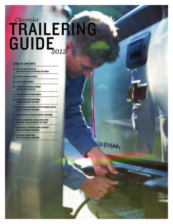
Inspecting & ReplacingBrake Magnets1Follow the procedures on page 13 for “Service Preparation”.2The magnet assembly can be inspected for wear while it isstill assembled to the brake. Lay a straight edge over the length ofthe magnet face andcheck for flatness.Straight EdgeAbnormal Wear(Replace)Normal WearAll AL-KO electric brakes use magnetsthat are similar in design. Properly functioningmagnets that show normal wear may be useduntil copper coil is visible through the frictionmaterial in the center of the magnet.4If magnet shows abnormal wear, inspect the brake drumarmature surface. The brake drum may also need to be replaced. (Seepage 22.)5If you suspect that the magnet is not functioning properly and itshows no sign of abnormal or excessive wear, check for a short circuit.Remove the magnet from the brake as follows. Disconnect the magnet leads from the trailer’s wiringharness and remove the strain relief, to allow the magnet leadsto be pulled through the backing plate. Remove clips holding magnet leads to the lever armor return spring. Remove clips holding magnet to lever arm andremove magnet. Keep the clips and magnet spring. Followprocedures on page 18.317
Magnet ElectricalEvaluationCoil To Housing Short Circuit Test1Connect one end of an ammeter (the ammeter must have aminimum scale of 5 amps) to either of the magnet wires. This testrequires only one of the magnet leads.Connect the other end of the2ammeter lead to the positive battery post.3Connect a separate piece of 16gauge wire from the negative battery postto the magnet housing.4If the ammeter registers current, ashort is indicated and the magnet must bereplaced per instructions on page 19.Note: The short may be intermittent. Ifthere is no initial reading tap the magnetand move the leads.Coil Short Circuit TestConnect one magnet wire to one of the ammeter leads.Connect the other magnet wire to the negative battery post.Connect remaining ammeter lead to positive battery post.1234 If the amperage reading at 12 volts isgreater than 3.2 amps, the magnet shouldbe replaced per instructions on page 19.5 If the amperage reading is lower than2.8 amps, check battery charge.Note: The magnets must be checked assoon as power is connected. Theamperage readings will drop as thetemperature increases.!Improper magnet function can result inreduced brake performance or loss ofbrakes. Reduced brake performance can lead to property damage,serious personal injury, or loss of life.WARNING18
Replacing Brake MagnetTo prevent serious eye injury, always wear safetyeye protection when you perform vehiclemaintenance or service.1Follow the procedures outlined on page 13for "Service Preparation".2Orient the magnet over the lever arm post such that the magnetleads are in the correctStrainposition for routing.Relief3Push magnet overSpringthe lever arm postcompressing the magnetspring between the magnetand the lever arm.Insert the magnet4clip in the slot of the magnet.Wire**Be sure to orient the magnetMagnetClipsPostclip so it will "snap" intoClipplace.Press down on the magnet and install the magnet clip.5Be sure that the magnet moves up and down freely on the lever6arm post.7Route the wiring in the same manner noted on removal. Be surethat wires cannot bind, pinch or rub. Manually actuate lever arm toinsure there is no interference.8Install strain relief bushing, allowing enough slack in the wiringto allow the lever arm to move without straining the wires. Be sure thewire cannot come in contact with the armature surface.Connect the magnet leads to the trailer wiring harness.9Reinstall hub and drum. (See page 23-24.)!WARNING Road test before using. Be sure area isclear of traffic and pedestrians. Do not exceed 30 m.p.h. Followprocedures outlined by the controller manufacturer. Failure to doso could result in property damage, serious personal injury, or lossof life.** Some brakes do not use wire clips. Route magnet wire with loomretaining ring, as previously installed.19
Inspecting BearingsRaces & SealsMost trailer axle bearings are unlike those in your motor vehicle in thatthey require periodic maintenance (see page 11) to ensure reliable, safeoperation of your trailer.1Follow the procedures outlined on page 13 for “ServicePreparation”. Refer to the schematic on pages 35-37.2Wash the bearings and races with solvent cleaner to remove allold grease. Do not use compressed air or steam. They may damagecomponents or cause components to come loose.3Check the bearings and races for worn, scored, damaged,grooved, indented, etched, spalled, gouged, nicked, corroded orotherwise damaged parts.Check seal for nicks, tears or wear.Replace damaged seals, bearings or races (see page 21).Always replace bearings and races in matched sets.45There is no need to lift the trailer beforegreasing axles equipped with Ultrulube: Remove the rubber plug from grease cap. Insert grease gun on the grease zerk. Pump until new grease begins to appear. Replace rubber plug.Hubs and components should also be disassembledyearly and inspected for worn or otherwisedamaged parts. (See schematics on pages 35-37.)PERMA-LUBE is a maintenance free,automotive type cartridge bearing system.To remove hub/drum for inspection ormaintenance: Remove the grease cap. Remove the spindle nut and washer. Remove drum, leaving sealed bearing intact. Replace drum, washer & nut. Torque nut to thevalue shown on the torque identifier, which is attachedto the spindle.Improperly torquedFASTENER TORQUEspindle nut can cause the hub/drumWARNING& wheel to separate from the axleresulting in property damage, serious personal injury, or loss of life.!20
Installing BearingsRaces & SealsTo prevent serious eye injury, always wear safetyeye protection when you perform vehiclemaintenance or service.Follow the procedures outlined on page 13 for“Service Preparation”.Install RacesAlways replace bearings and races as a set. Install races (new hub/drums should have races already installed) using a mild steel drift or bar.Do not use hardened steel or brass bars as they may damage, chip orleave deposits on the races. Final setting of the race against theshoulder should be checked with feeler gauges and be within 0.002" ofthe shoulder in the hub/drum.Pack BearingsPrior to repacking bearings, all grease must be removed from the hub/drum and bearings. Bearings should be packed by machine or by handmethods to insure that grease is forced into the cavities between therollers, cone and cage of the bearings. For axles equipped with Ultrulubeor Perma-Lube, refer to page 20.GreaseUse a high temperature, automotive type wheel bearing greaseproduced by a reputable manufacturer. The soap type should be lithiumcomplex or equivalent. Use NLGI Grade 2 productwith a minimum dropping point of 440o F.Installing SealsIt is recommended to install a new seal after removing the hub/drum.Be sure that the inner race and fully packed inner bearing are installed.Use the correct size seal driver. If this is not available, use a cleanblock of wood which is large enough to cover the entire seal. Tap blockto seat seal.Improper seal or bearing installation oror insufficient maintenanceWARNING adjustmentcan lead to wheel bearing failure whichcould cause the hub/drum and wheel to separate from the axleduring operation resulting in property damage, serious personalinjury, or loss of life.!21
Brake DrumInspecting The Brake DrumFollow the procedures outlined on page 13 for “Service Preparation”.Check the armature surface for excessive galling due to severecontamination (mud, stones, etc.). One or two light score marks are notcause for resurfacing or replacing the brake drum. Under normalconditions, the armature surface should last indefinitely.Inspect the drum’s shoe surface. This surface should have a dull grayappearance and be free from heavy scoring and/or excessive wear.One or two light score marks are not cause for resurfacing or replacingthe brake drum. If there are any questions concerning the condition of adrum, consult an expert. Drums heavily scored, worn to more than0.020" oversize, or with 0.015" runout should be replaced or resurfaced.Do not exceed the maximum diameter cast in the brake drum.!Heavily scored, worn or oversizeddrums can result in reduced brakeperformance or loss of brakes. This could result in propertydamage, serious personal injury, or loss of life.WARNINGResurfacing The Brake DrumA standard drum lathe may be used to machine the shoe surface. Donot exceed the maximum diameter cast into the brake drum. The drumshould be replaced if it must be bored more than the maximum diametercast in the brake drum.Armature surface machining is a difficult process with most drum lathes
Torque wheel nuts now and then every fifty miles for the first 200 miles and then according to the schedule on page 11. Over or under torqued wheel nuts can cause the wheel to separate from the wheel mounting surface during operation. Wheel separation can result in property damage, serious personal injury, or loss of life. (See page 24 for