Transcription
Pilot’s ManualSECTION VFLIGHT CONTROL SYSTEMS &AVIONICSTABLE OF CONTENTSFlight Control Systems . 5-1Aileron . 5-1Roll Disconnect . 5-1Control Wheel . 5-2Control Wheel (Figure 5-1) . 5-2Elevator . 5-2Elevator Disconnect. 5-3Elevator Disconnect (Figure 5-2). 5-3Rudder. 5-4Rudder Pedal Adjustment Switches . 5-4Rudder Boost . 5-5Controls Gust Lock . 5-6Controls Gust Lock (Figure 5-3) . 5-6Flaps. 5-7Flap Control Lever. 5-8Flap Position Indication . 5-8Spoiler Systems . 5-9Normal Spoiler Mode. 5-10Autospoilers . 5-10Spoileron Operation . 5-11Spoileron (Roll Disconnect Mode of Operation) . 5-12Spoiler Indications . 5-13Spoiler Monitor System . 5-14Pitch Trim . 5-15Pitch Trim Selector Switch . 5-15Primary Pitch Trim . 5-16Trim Switch Panel (Figure 5-4) . 5-16Bypass Trim. 5-17Secondary Pitch Trim . 5-18Autopilot Pitch Trim. 5-19Trim-In-Motion Indication. 5-19Pitch Trim Bias. 5-20Configuration Trim. 5-20Aileron Trim. 5-21Rudder Trim . 5-22PM-126AV-1
Pilot’s ManualTABLE OF CONTENTS (Cont)Trim Indications. 5-23Pitch Trim Indications. 5-23Aileron Trim Indications . 5-24Rudder Trim Indications . 5-24Mach Trim. 5-25Stall Warning System . 5-26Stall Warning Indications . 5-26Stall Warning Operation. 5-27Stall Vane Anti-Ice . 5-27Stall System Test . 5-28Angle of Attack Indicators (Optional). 5-29Instrument Panel Layout and AOA Indicator Position(Figure 5-5). 5-29Avionics . 5-30Honeywell Primus 1000 Avionics System . 5-30Electronic Flight Instrument System (EFIS). 5-30IC-600 Power Source . 5-31Avionics Master Switches. 5-32Electrical Control Panel (Figure 5-6). 5-32Air Data System (ADS). 5-33Pitot-Static System. 5-33Pitot-Static System Schematic (Figure 5-7). 5-33Standby Pitot-Static System Schematic (Figure 5-8) . 5-34Air Data Computers (ADCs) . 5-35ADC Reversion . 5-35Standby Instruments. 5-36Standby Instrument Group (Figure 5-9) . 5-36Standby Altimeter . 5-36Standby Airspeed/Mach Indicator. 5-36Standby Attitude Indicator . 5-37Standby Compass. 5-37Attitude Heading Reference System (AHRS). 5-38Attitude and Heading Comparison Monitors. 5-39AHRU Power Source & Cooling . 5-40AHRS Reversion. 5-40Electronic Display System (EDS) . 5-41Primary Flight Display (PFD). 5-42Primary Flight Display and Bezel Controller(Figure 5-10). 5-43Bezel Controllers. 5-43Multi-Function Display (MFD) . 5-44V-2PM-126A
Pilot’s ManualTABLE OF CONTENTS (Cont)EICAS Display. 5-45Display Controllers. 5-46EICAS Display and BL-871 Bezel Controller(Figure 5-11). 5-46Display Controller (Figure 5-12) . 5-47Display Unit Reversion Panels . 5-48Display Unit Reversion Panels (Figure 5-13) . 5-48Data Acquisition Units (DAUs) . 5-49Reversionary Control Panel (Figure 5-14) . 5-49Radio Management Units (RMUs) . 5-51Radio Management Unit (Figure 5-15) . 5-51RMU Cross-Side Operation. 5-52RMU Backup Pages . 5-52VHF Com Tuning. 5-53FMS Tuning. 5-54NAV Tuning. 5-54ADF Tuning . 5-55Transponder/TCAS Tuning . 5-56TCAS (Optional) . 5-56TCAS Operation. 5-57System Controls and Displays . 5-58Traffic Display Symbols . 5-58Enhanced Ground Proximity Warning System (EGPWS). 5-59Audio Control System. 5-60Digital Audio Control Panel (Figure 5-16) . 5-61Clearance Delivery Radio (CDR). 5-63Clearance Delivery Radio (Figure 5-17) . 5-64Flight Guidance Control System . 5-65Flight Director . 5-65Flight Guidance Controller (FGC). 5-66Flight Guidance Controller (Figure 5-18). 5-66Autopilot/Yaw Damper . 5-69AP/YD Annunciation . 5-70Control Wheel Trim Switch . 5-70Control Wheel Master Switch (MSW). 5-70Touch Control Steering (TCS) . 5-71Autopilot Engagement/Disengagement. 5-71Yaw Damper Engagement/Disengagement. 5-72Mistrim Annunciation. 5-72Power Supply Configuration . 5-72Go-Around (GA) Button . 5-73PM-126AV-3
Pilot’s ManualTABLE OF CONTENTS (Cont)Flight Management System (FMS). 5-73Control Display Unit (CDU) . 5-74UNS-1E FMS CDU (Figure 5-19) . 5-74Data Transfer Unit (DTU). 5-75Configuration Module. 5-75FMS Functions . 5-75Weather Radar . 5-77WU-650 Weather Radar Control Panel (Figure 5-20) . 5-77Avionics Cooling . 5-78Instrument Panel Cooling . 5-78Miscellaneous . 5-79Cockpit Voice Recorder (CVR) . 5-79Clocks . 5-80Multi-Function Chronometer and Instrument Location(Figure 5-21). 5-80Hourmeter-Aircraft (Optional). 5-81Flight Data Recorder (FDR) (Optional) . 5-81Emergency Locator Transmitter (Optional). 5-81Dorne & Margolin ELT14 . 5-81Transmitter and Antenna . 5-81Transmitter Switch (ARM/OFF/ON) . 5-81Remote Control and Monitor Unit. 5-82Operation. 5-82ARTEX ELT 110-406. 5-83Transmitter and Antenna . 5-83Transmitter Switch (ON-OFF) . 5-83Cockpit Switch and Indicator Light. 5-84Buzzer . 5-84Operation. 5-84V-4PM-126A
Pilot’s ManualSECTION VFLIGHT CONTROL SYSTEMS &AVIONICSFLIGHT CONTROL SYSTEMSThe primary flight controls (ailerons, elevator, and rudder) are mechanically operated through the control columns, control wheels, and rudder pedals. The flaps and spoilers are hydraulically actuated andelectronically controlled. Airplane trim systems (pitch, roll, and yaw)are electronically controlled.AILERONThe aileron control system consists mainly of three control circuits, onein the fuselage area and one in each of the left and right wing area. Inaddition, a disconnect mechanism is incorporated into the pilot’s control wheel which allows the disconnection of the aileron control system(in the event of a jam) and switching to spoileron system for roll control.The fuselage control circuit connects both pilot’s and copilot’s controlwheels together, and each wing control circuit is connected to the aileron drive mechanism. The three control circuits are connected togethervia a common sector assembly. In normal operation, whether by an input from the autopilot or by manual input to one of the two controlwheels, the two control circuits will move in unison to drive the two aileron panels. The aileron control system is considered the primary system for roll control and is interfaced with the spoileron system for rollaugmentation.ROLL DISCONNECTIf ailerons become jammed, the aileron control system can be disconnected and the spoileron system can be used for roll control. The pilot’scontrol wheel is disconnected from the aileron cables and copilot’s control wheel by the red lever labeled ROLL DISC located on the hub of thepilot’s control wheel. This will also disconnect and prevent engagement of the autopilot. Safe flight can continue on spoilerons alone. Formore information on roll disconnect, see Spoileron (ROLL DISCONNECT) system.PM-126A5-1
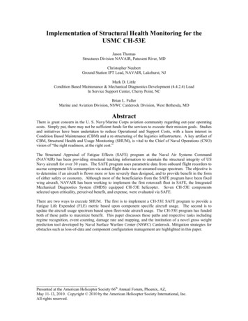
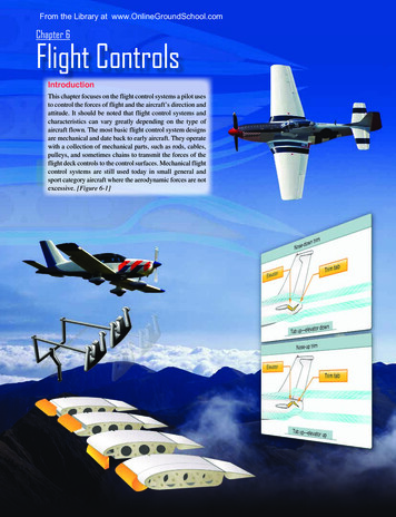
Pilot’s ManualCONTROL WHEELEach flight station is equipped with a U-shaped control wheel. The pilot’s control wheel is equipped with a disconnect assembly which employs a red lever labeled ROLL DISC located on the inboard side of thecontrol wheel hub (Figure 5-1). Each control wheel contains the following switches: Control Wheel Trim, Control Wheel Master (MSW), MIC,IDENT, Touch Control Steering (TCS), and Checklist Line Advance.TOUCHCONTROLSTEERING(TCS)ROLL DISC LEVER(PILOT'S SIDE ONLY)ARMBUTTONCONTROL WHEELTRIM SWITCHCHECKLISTLINE ADVANCEIDENTSWITCHMICSWITCH(NOT SHOWN)CONTROL WHEELMASTER SWITCH(MSW)CONTROL WHEELFigure 5-1ELEVATORMovement of the control columns is mechanically translated into elevator surface movement through levers, bellcranks, sectors, cables, andpushrods. The elevator control system consists of two parallel controlcircuits. The two control circuits are normally connected together viaforward and aft disconnect assemblies in which either control columnmoves both the left and right elevator surfaces in union. A mechanicalup/down spring is also used in the system to augment high and lowspeed trim ability of the airplane. If a jam occurs in either mechanicalcontrol circuit, an elevator disconnect feature is incorporated into thesystem.5-2PM-126A
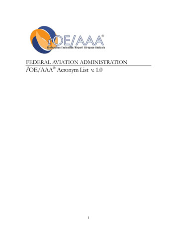
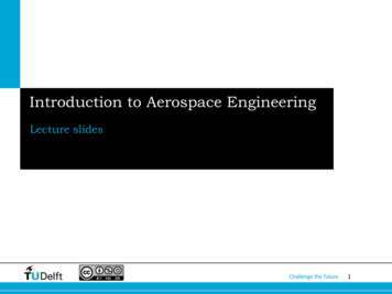
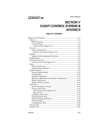
Pilot’s ManualELEVATOR DISCONNECTIn the event of an elevator jam, the two cable circuits can be disconnected by pulling the red ELEV DISC T-handle (Figure 5-2) located at theleft-forward edge of the pedestal. The airplane will then be controlledwith the unjammed elevator. The forward and aft disconnect assemblies are dog clutch devices that are operated simultaneous by the handle being pulled. When the ELEV DISC T-handle is pulled, a cableconnected to the handle shaft is pulled which disengages the forwardclutch thereby disengaging the two control columns. Electrical switches sense the movement of the shaft and signal the aft disconnect to disengage.EVE DPIT TRIMBIASSYS TEST// RESETG FE RA ER EFAL IE SANTI-ICEV BOOSTSQNAVAUDIOLLMODESGEARFLAPOFFVOLLLP DU OS WH NUSEABLE FUEL TOTAL: 6000 LBSRADIO CTLHOT BUS2404FUSELAGEONELEVSPOE DRETARMILL IE SRFLAPSEXTGO AROUNDMUTEUPV CSR WINGEDIC17981798L PULL &25020200MFD JOYSTICKDN150EMERGENCY/PARKINGBRAKEULLELEVATOR DISCONNECTFigure 5-2When the handle is pulled to full extension, it must be rotated 90 ,either clockwise or counterclockwise, to lock it in the disconnect position. The elevator forward disconnect is a mechanical clutch mechanism located on the torque tube between the control columns. Theclutch is held open when the ELEV DISC T-handle is pulled and lockedin the extended position. This will disconnect and prevent engagementof the autopilot.PM-126A5-3
Pilot’s ManualThe elevator aft disconnect is an electro-mechanical device located inthe top of the vertical stabilizer. When the ELEV DISC T-handle ispulled, a two-position linear actuator on the elevator aft disconnect assembly is energized to the extended position (disconnected position),separating operation of the two elevators. The linear actuator will remain in the extended position. When the elevator aft disconnect is actuated, the elevator disconnect sensor will send a signal to display amessage on the Crew Alerting System (CAS). Do not reconnect. Obtainmaintenance prior to next flight. Electrical power used by the elevatordisconnect system is through the ELEV DISC circuit breaker located onthe pilot’s circuit breaker panel (FLIGHT group).The following CAS illuminations are specific to the elevator disconnect:CASELEVATOR DISCELEVATOR DISCColorDescriptionAmber Elevator disconnect has split the elevatorcontrols on the ground. Obtain maintenanceprior to flight.White Elevator disconnect has split the elevatorcontrols during flight. Do not reconnect.RUDDERDirectional control is provided by a dual closed-loop cable system withseparate parallel paths in the engine area for rotor burst considerations.Rudder pedal movement is mechanically translated into rudder controlsurface movement through cables, pulleys, and bellcranks. There is anelectrically driven rudder boost system to provide additional ruddercontrol power in the event of an engine-out on takeoff.RUDDER PEDAL ADJUSTMENT SWITCHESThe pilot’s and copilot’s rudder pedals are individually adjustable witha spring-loaded toggle switch to accommodate differences in crew size.The pilot operated toggle switch controls a linear actuator which provides forward and aft pedal adjustment. This toggle switch is labeledRUDDER PEDAL, and located on the lower outboard corner of the pilot’s and copilot’s switch panel. Each switch has three positions: FWD,Off, and AFT. Only the FWD and AFT positions are labeled. The rudderpedal adjustment is powered by 28-vdc supplied through two 3-ampcircuit breakers, L RUD ADJUST and R RUD ADJUST, on the pilot’sand copilot’s circuit breaker panels (FLIGHTgroup).5-4PM-126A
Pilot’s ManualRUDDER BOOSTThe rudder boost system is provided to reduce rudder forces. Signalsfrom force sensors in both sets of rudder pedal mechanisms are read bythe ICs. The ICs then send rudder boost signals to the yaw damper servo. Rudder boost provides yaw servo torque proportional to rudderpedal force, when either the pilot’s or copilot’s rudder pedal force orthe sum of their forces reaches 50 pounds. The rudder boost will override the yaw damper (if engaged) when this threshold is reached. Whenthe force on the rudder pedals is released, the yaw damper will resumeoperation. The rudder boost system is armed when flap extension isgreater than 3 and the RUD BOOST switch is selected to On. The RUDBOOST switch is located on the forward pedestal. When selected On,the switch is dark and when selected OFF, OFF will be displayed in thecenter of the switch. A white CAS illuminates when the switch is OFFor the system is disabled by the IC or the yaw force interface box. Anamber CAS illuminates when the system is inoperative and not selected OFF.Dual, redundant power inputs are provided via the RUD FORCE circuit breaker on the right essential bus and the NOSE STEER COMPUTER circuit breaker on the left essential bus. If both these power sourcesshould fail, the #2 IC-600 will disable rudder boost and provide appropriate annunciation.The following CAS illuminations are specific to the rudder boostsystem:CASRUD BOOST INOPRUD BOOST INOPPM-126AColorDescriptionAmber Rudder boost is inoperative and not selectedOFF. Do not takeoff.White Rudder boost is selected OFF. Do not takeoff.5-5
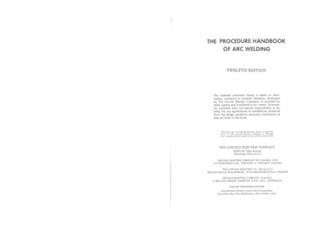
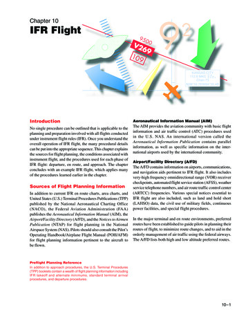
Pilot’s ManualCONTROLS GUST LOCKA gust lock is provided to help prevent wind gust damage to moveablecontrol surfaces. The gust lock is installed on the pilot’s side only, withcontrol wheel rotated counterclockwise until the bend in the handlealigns with the column, and the rudder pedals are centered. Loopstraps around bottom heel, and draw both left and right pedal strapstaut to seat control column against the primary stop. When installed,the gust lock secures the flight controls in the rudder centered, fullaileron, and full down elevator position.CONTROLS GUST LOCKFigure 5-35-6PM-126A
Pilot’s ManualFLAPSThe airplane’s single-slotted Fowler flaps are electronically controlledand operated by a hydraulic motor (flap power unit). Each flap panel,one on each wing, has three safe-life flap tracks and is driven by twoscrew jack actuators. A flexible drive shaft transfers power from the hydraulic motor to each flap actuator. The flap control lever is located onthe center pedestal and is recessed to prevent inadvertent operation.The flap control lever has settings at 0 (up), 8 , 20 and 40 (down). Toselect a new flap position, the flap control lever is moved directly to thedesired setting. Flap position is controlled by a microprocessor basedcontroller (Flap Control Unit). The Flap Control Unit receives positioncommand information and an arming signal from the flap control leverin the cockpit. It then provides the electrical arming and control signalto the arming solenoid valve located in the flap power unit and receivesa feed-back signal from sensors mounted on the outboard actuator ofeach flap panel. When flaps are extended or retracted in flight, the configuration trim system automatically applies the appropriate amountof pitch trim to compensate for the pitching moment caused by flap repositioning.The Flap Power Unit (FPU) is located under the center wing and contains the hydraulic motor, a servo control valve, an arming solenoidvalve and a pressure switch. The servo valve responds to electrical signals from the flap control unit and meters hydraulic pressure to the extend or retract side of the bidirectional hydraulic motor. The armingsolenoid valve must be energized open by the flap control unit beforehydraulic pressure is available to the servo valve. The pressure switch,located upstream of the servo valve, monitors system pressure betweenthe arming solenoid valve and the servo valve. If pressure is not available on flap selection, flaps will be inoperative, but if pressure is available without a selection command, the FPU will show a fault and theflaps will operate in a degraded mode, i. e. the flaps may deploy at areduced speed when selected. These will cause the following CAS illuminations in order described above.The following CAS illuminations are specific to the Flap System:CASFLAPS FAILFLAPS FAULTPM-126AColorDescriptionAmber The flap system has failed and the flaps areinoperative.Amber The flap system is operating in a degradedmode.5-7
Pilot’s ManualFlexible drive shafts routed along the rear wing spar transmit the rotarymotion of the flap power unit to the input shaft of each of the flap actuators. Two Rotary Variable Differential Transformers (RVDTs) mountedon the outboard side of each outboard flap actuator provide position information to the flap control unit and the flap position indicating unit.The flap actuators incorporate a screw jack and are attached to the rearspar. These actuators convert the rotary input motion into linear outputmotion through these screw jacks thus driving the flaps. Each actuatorhas overtravel end stops. Uncommanded retraction due to airloads, vibration, etc., is prevented by the screw jack design of the flap actuators.The flap control system operates on 28-vdc supplied through a 3- ampFLAP CTRL breaker located on the copilot’s circuit breaker panel(FLIGHT group).FLAP CONTROL LEVERThe FLAP control lever will operate in one of four positions (UP, 8 , 20 ,and DN) with detents at the 8 and 20 positions. When retracting flaps,there is a gate at the 8 position; therefore, the lever must be pulled outslightly when raising the flaps above 8 . The lever is attached to dualRVDTs co-located with a flap lever detent switch within the throttlequadrant. These dual RVDTs transmit the selected position to a flapcontrol unit. Moving the lever between positions actuates the flap leverdetent switch and energizes a 75-second timing circuit within the flapcontrol unit. This circuit allows the arming solenoid valve within theflap power unit to energize open for 75 seconds and then de-energizes.Normal flap extension from 0 to 40 will not exceed 10 seconds withengine-driven hydraulic pumps operating. However, this time will extend up to 60 seconds when using HYD XFLOW while lowering flapsfrom 0 to 20 in flight.FLAP POSITION INDICATIONThe flap position indicating unit has two separate and independentchannels. Channel 1 provides left side equipment and Channel 2 provides right side equipment. Both channels are housed in a commonchassis. Flap position is shown full time in a digital display on theEngine Indicating and Crew Alerting System (EICAS). The EICAS display is framed with a white box when the flaps are not in the selectedposition in flight, or on the ground with flaps not set for takeoff. TheEICAS display turns red if power is advanced for takeoff and flaps arenot properly set. The display turns amber if there is a fault or failure inthe flap system. Flap selection and position are also displayed on theright side of the FLT (flight) system schematic page. The FLT systemschematic display can be displayed on the EICAS or Multi-FunctionDisplay (MFD).5-8PM-126A
Pilot’s ManualSelected flap position is indicated by a horizontal magenta line acrossthe vertical scale. Actual left and right flap position is indicated by flapposition pointers on each side of the vertical scale. When flaps havemoved to their selected position, the pointers will overlay the magentaline. Flap position pointers turn red on the ground when power is advanced for takeoff and flaps are not properly set. Pointers turn amberwhen there is a fault or failure in the flap system. A digital indication offlap position is provided on the backup engine/systems page of theRadio Management Unit (RMU).SPOILER SYSTEMSSpoilers, one on the upper surface of each wing forward of the flaps, areprovided for deceleration. The spoilers are electrically controlled andhydraulically operated. The spoilers are extended symmetrically foruse as spoilers/speed brakes or asymmetrically for aileron augmentation. Each spoiler is hinged at four points and is extended or retractedwith a single hydraulic actuator. The spoiler control lever, located onthe left side of the throttle quadrant, is linked to two RVDTs. There arethree labeled settings for the spoiler lever that correspond to detent positions: RET (retract), ARM (autospoilers), and EXT (full extension) approximately 60 at slower airspeeds. The range between the ARMand EXT detents allow for variable spoiler positions in flight. There arealso two unmarked detent positions between ARM and EXT which correspond to intermediate spoiler extension positions of approximately15 and 30 . At high airspeeds the actuators cannot extend the spoilersfully; therefore, spoileron computer commands to the actuator servosare limited by airspeed inputs from the Air Data Computers (ADCs).At speeds below 175 knots, spoilers will extend to 60 when the spoilercontrol lever is placed to EXT; however, at higher speeds full extensionis not possible.PM-126A5-9
Pilot’s ManualNORMAL SPOILER MODEThe spoilers can be extended symmetrically on the ground or in flightby moving the spoiler lever aft of the ARM position. Placing the leverto any position aft of ARM while on the ground will cause full extension (60 ) of the spoilers. Spoiler extension on the ground requires
lot's control wheel is equipped with a disconnect assembly which em-ploys a red lever labeled ROLL DISC located on the inboard side of the control wheel hub (Figure 5-1). Each control wheel contains the follow-ing switches: Control Wheel Trim, Control Wheel Master (MSW), MIC, IDENT, Touch Control Steering (TCS), and Checklist Line Advance .