Transcription
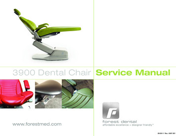
3900 Dental Chair Service Manualwww.forestmed.comforest dentalaffordable excellence designer friendly 08-08-11 Rev.- 0097-381
COPYRIGHT 2011 – BY FOREST DENTAL PRODUCTS INC.6200 NE CAMPUS COURT, HILLSBORO OR 97124PRINTED IN U.S.A.WARRANTYTRADEMARKSFOREST DENTAL PRODUCTS WARRANTS ITS PRODUCTS TO BEFREE FROM DEFECTS IN MATERIAL AND WORKMANSHIP ONLY.NO OTHER WARRANTIES ARE EXPRESSED OR IMPLIED. THISWARRANTY SHALL EXTEND FOR FIVE YEARS UNLESSOTHERWISE STATED. W RITTEN NOTICE OF BREACH MUST BEGIVEN TO F OREST DENTAL PRODUCTS WITHIN THIS PERIOD.BUYERS REMEDY FOR BREACH OF THIS WARRANTY IS LIMITEDTO REPAIR PARTS OR REPLACEMENT OF ITEMS BY F ORESTDENTAL PRODUCTS INC. THIS WARRANTY IS VOID IF ITEMSARE CARELESSLY USED OR IMPROPERLY MAINTAINED ORINSTALLED. T HIS WARRANTY DOES NOT COVER DAMAGE THATRESULTS FROM USING CLEANING, DISINFECTING ORSTERILIZATION CHEMICALS AND PROCESSES. THIS WARRANTYDOES NOT COVER LIGHT BULBS. HANDPIECE ILLUMINATIONAND HEATED SYRINGE TUBINGS ARE WARRANTED FOR SIXMONTHS TO BE FREE FROM DEFECTS IN MATERIAL ANDWORKMANSHIP ONLY. F ACTORY REPAIRS ARE COVERED FOR APERIOD OF 90 DAYS. N O CLAIM FOR LABOR ORCONSEQUENTIAL DAMAGES WILL BE ALLOWED.FOREST LOGOS ARE REGISTERED TRADEMARKS IN THE U.S.PATENT AND TRADEMARK OFFICE.
WELCOMEW ELCOME TO THE 2011 EDITION OF THE FOREST 3900DENTAL CHAIR PARTS AND SERVICE MANUAL. THIS MANUALIS AN EASY TO USE SOURCE OF TECHNICAL INFORMATION FORSERVICING THEFOREST MODEL 3900 DENTAL CHAIR.INTENDED AUDIENCETHIS MANUAL IS INTENDED FOR NEWLY TRAINED ANDEXPERIENCED DENTAL EQUIPMENT REPAIR TECHNICIANS.WEASSUME YOU UNDERSTAND THE OPERATION OF DENTALEQUIPMENT AND CAN FOLLOW FLOW DIAGRAMS.
TABLE OF CONTENTSP AGEOVERVIEWSERVICE AND SUPPORTLOCATING THE MODEL/SERIAL NUMBERPOWER ON INDICATORREMOVING AND INSTALLING CHAIR COVERST HE HYDRAULIC SYSTEMFLOW DIAGRAMSERVICE PARTSSOLENOID MANIFOLD ASSEMBLYREMOVING A FAULTY SOLENOIDINSTALLING A NEW SOLENOIDADJUSTMENTSCHAIR ELECTRICAL SYSTEMCIRCUIT BOARDDIAGRAMSERVICE PARTST ESTING AND PROGRAMMING THE CHAIRSETTING HARD LIMITSPROGRAM CHAIR AUTO-POSITIONING FUNCTIONSRUNNING THE CHAIR SELF T ESTT ROUBLESHOOTINGADJUSTING THE POSITION SENSING POTENTIOMETERSPARTS BREAKDOWNSPECIFICATIONSDIMENSIONS 45567891011121315161718191923252633353940
Model 3900 Dental ChairOVERVIEWThe Forest Model 3900 Dental Chair is an electronicallycontrolled, hydraulically powered chair. The Touchpad andFootswitch are used to position the chair and programauto-positioning functions into the chair. The chairhydraulic system is controlled by the electronics usingelectro-mechanical relays and electrically poweredsolenoid valves.This section provides information related to locating thechair model/serial number, servicing the chair,troubleshooting, and adjustments that can be made to thechair.Service and SupportGiven the proper care, the Forest Model 3900 Dental Chairwill provide years of trouble-free service. If somethingdoes go wrong with the chair and you are unable to correctthe problem, call Forest Dental Products Customer Service800.423.3555. When you call, be prepared to provide thefollowing:1. Serial number and, if known, the approximate datethe chair was purchased.2. Symptoms of the problem.3. What steps you have taken towards correcting theproblem.8/8/2011 Rev. - 0097-381Page 4
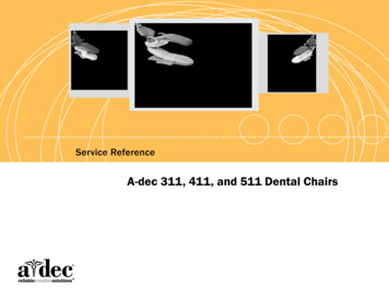
Model 3900 Dental ChairLocating the Model/Serial NumberPower ON IndicatorThe model/serial number tag identifies the chair as beingmanufactured by Forest Dental Products and allowsCustomer Service to determine when the chair wasmanufactured. The date of manufacture is very important indetermining the chair warranty status as well as theengineering revision.The Power ON Indicator, when illuminated, indicates thatthe chair has mains electrical power available.POWER ONINDICATORSERIAL NUMBER TAG8/8/2011 Rev. - 0097-381Page 5
Model 3900 Dental ChairRemoving and Installing Chair CoversThe Forest 3900 chair motor pump, small arm cover andsafety plate covers are removed as follows:23910-030-SH33912-031-G3912-031-SH4Small Arm Cover, Shadow, 2” Holefor 1590 UmbilicalSafety Plate, Gray, includes item 4Safety Plate, Shadow, includes item 4Safety Plate Retaining ScrewMotor Pump CoverUsing a 5/32” hex key, remove the two button headscrews from each side of the cover and lift it.Small Arm CoverUsing a 7/64” hex key, remove the four button headscrews from the cover.Safety PlateUsing a flat tip screwdriver, remove the single screw fromthe safety plate. The Safety Plate will drop when thescrew is removed.Item1Part 028-SH3910-029-G23910-029-SH3910-030-G8/8/2011 Rev. - 0097-38121DescriptionMotor Pump Cover, GrayMotor Pump Cover, ShadowScrew, Pump CoverSmall Arm Cover, GraySmall Arm Cover, ShadowSmall Arm Cover, Gray, 1-1/4” Holefor 1090 UmbilicalSmall Arm Cover, Shadow, 1-1/4”Hole for 1090 UmbilicalSmall Arm Cover, Gray, 2” Hole for1590 Umbilical3Page 6
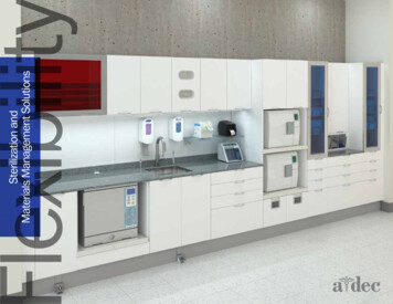
Model 3900 Dental ChairTHE HYDRAULIC SYSTEMThe hydraulic system consists of:ItemDescriptionA hydraulic fluid reservoir or tank thatperforms a number of functions in thedental chair hydraulic system:1 Fluid storage Separation of air from fluid Dissipation of heat Settling of contaminantsThe fluid level in the reservoir can be seenthrough the sides of the reservoir; thereservoir is serviced via a top fill cap.2Hydraulic cylinders that convert hydraulicfluid pressure to mechanical movementlifting the chair base and back. Springs andgravity retract the cylinder rods for downmovements.3A chair hydraulic pump that is driven by athermally protected electric motor. Thepump provides fluid, under pressure, to thecylinders.8/8/2011 Rev. - 0097-381ItemDescription4A solenoid manifold assembly that controlsthe flow of hydraulic fluid to and from thechair cylinders using electrically operatedvalves. The assembly includes four speedcontrol valves used to restrict the flow offluid to and from the cylinders controllingthe chair’s rate of travel up and down. Theassembly also includes an adjustablepressure relief valve and two check valves.Page 7
Model 3900 Dental ChairFlow Diagram8/8/2011 Rev. - 0097-381Page 8
Model 3900 Dental ChairService PartsItemPart Number13910-021Back Tilt Cylinder, 3900 Chair23910-020Base Lift Cylinder, 3900 Chair3912-026Hydraulic Motor Pump, 3900 Chair,110VAC3912-027Hydraulic Motor Pump, 3900 Chair,230VAC3912-028Motor Start Run Capacitor, 45uf,110VAC3912-029Motor Start Run Capacitor, 14uf,230VAC3910-001Hydraulic Fluid Reservoir, 3900Chair3910-002Hydraulic Fluid Reservoir, 3900Chair with 16 oz. Hydraulic Fluid3914-047Solenoid Manifold Assy, 110VAC3914-050Solenoid, Single, 3900, 110VAC3914-049Solenoid Manifold Assy, 230VAC3914-051Solenoid, Single, 3900, 230VAC345678/8/2011 Rev. - 0097-381DescriptionElbow Fitting, Hydraulic CylinderPage 9
Model 3900 Dental ChairSolenoid Manifold d Manifold Assy, 110VAC,complete with 4 solenoids3914-049Solenoid Manifold Assy, 230VAC,complete with 4 solenoids3914-050Solenoid, Single, 3900, 110VAC3914-051Solenoid, Single, 3900, 230VAC8/8/2011 Rev. - 0097-381Page 10
Model 3900 Dental ChairRemoving a Faulty SolenoidThe following steps will guide you through the process ofremoving a faulty solenoid.WARNINGThe solenoids are powered by mains voltage (120 or 240VAC). Failing to unplug the chair from mains voltage mayresult in serious injury from electrical shock.TaskProcedure1To depressurize the chair hydraulic system, lowerthe base and back to full down. Remove the motorpump cover and unplug the chair.2Remove the two screws that secure the manifold tothe chair hydraulic tray. Turn the manifold to accessthe solenoids.3Using a Philips screwdriver, remove the faultysolenoid coil.4Cut the faulty solenoid wires approximately 4” fromthe solenoid. Discard the faulty solenoid.5Remove the solenoid stem and o-ring from themanifold cavity.Refer to page 12 for installation instructions.8/8/2011 Rev. - 0097-381Page 11
Model 3900 Dental ChairInstalling a New SolenoidThe following steps will guide you through the process ofinstalling a new solenoid.WARNINGThe solenoids are powered by mains voltage (120 or 240VAC). Failing to unplug the chair from mains voltage mayresult in serious injury from electrical shock.TaskProcedure1Install the new solenoid o-ring and stem in themanifold cavity.2Using a Philips screwdriver, install the new solenoidcoil.3Connect the stripped wires from the new solenoid tothe stripped wires from the chair circuit board withthe two wire nuts provided.4Reinstall the manifold assembly to the chairhydraulic tray.5Plug in the chair and test all chair functions.6Carefully inspect the manifold for any hydraulic oilleakage, if none is found, reinstall the motor pumpcover.8/8/2011 Rev. - 0097-381Page 12
Model 3900 Dental ChairAdjustmentsCV1 and CV2 Check ValvesAdjusting the Rate of TravelWhen the chair base or back are positioned up, the CV1and CV2 check valves will prevent the chair base or backfrom drifting down until a down solenoid is opened.The hydraulic manifold assembly includes four speed controlThrottle Valves (TV1, TV2, TV3 and TV4). Each TV functionmeters the flow of hydraulic fluid to and from the hydrauliccylinders.BACK DOWNBASE DOWNCAUTIONNever completely close a Throttle Valve, the motor pump mayoverheat, possibly damaging the pump motor. Do notcompletely remove a Throttle Valve from the manifold.TaskProcedureAdjust Base UpSpeedTurn the Base TV3:Clockwise to decrease speedCounterclockwise to increase speedAdjust BaseDown SpeedTurn the Base TV4:Clockwise to decrease speedCounterclockwise to increase speedAdjust BackDown SpeedTurn the Back TV2:Clockwise to decrease speedCounterclockwise to increase speedAdjust Back UpSpeedTurn the Back TV1:Clockwise to decrease speedCounterclockwise to increase speed8/8/2011 Rev. - 0097-381BACK UPBASE UPPage 13
Model 3900 Dental ChairAdjusting the Pressure Relief ValveThe pressure relief valve is a spring operated/loaded safetydevice that relieves hydraulic fluid overpressure in the chairhydraulic system. If excessive pressure develops in the chairhydraulic system, the pressure relief valve will open routingfluid to the reservoir. An incorrectly adjusted pressure reliefvalve may result in a condition known as “hydrostatic lock” orthe chair not being able to lift the patient.To adjust the valve, turn it clockwise until it seats thencounterclockwise 1-1/2 turns.8/8/2011 Rev. - 0097-381Page 14
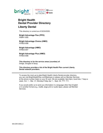
Model 3900 Dental ChairChair Electrical SystemCircuit BoardThe Forest Model 3900 Dental Chair circuit board has therelays necessary for controlling the chair motor pump andsolenoids. The circuit board is also equipped with a testfunction that allows verification of the chair functions without afoot switch or a touchpad.Item8Back Up/Down Solenoids Out.9Mains Power In, 115VAC-125V, 50-60Hz.101112To access the chair circuit board, remove the motor pumpcover.NOTE: Any circuit board components not identified are notbeing used or are non-functional.Item1 Enable programming the chair hard limits. Enable initiation of the chair self test.Normally both switches are OFF.2Self Test Button.3AN1-AN4, Touch Pads and Footswitches.4Power indicator LED.5Mains Aux Power Out, 7 Amps maximum.6Motor Pump Power Out, 3 Amps.7Base Up/Down Solenoids Out.8/8/2011 Rev. - 0097-381Fuse, F1 and F2, 115V, 10A, 5x20mm.Fuse, F1 and F2, 230V, 6.3A, 5x20mm.Motor Pump and Solenoid Relays.Fuse, F3, 115V, 125mA, 5x20mm.Fuse, F3, 230V, 63mA, 5x20mm.13AN12-AN15, Jumpers installed, do not remove.14LED1-LED5, Illuminate when associated relay isenergized.15Base and Back Position SensorsAN6: Back Position SensorAN7: Base Position Sensor16AN4, “M” Button (Program and Override Safety Platefunction).17AN10, Safety Plate Switches.DescriptionSW, Dual switch DIP, used to:DescriptionAN10 Test Jumper, P/N 0014-287. Used to shortAN10.Page 15
Model 3900 Dental Chair8/8/2011 Rev. - 0097-381Page 16
Model 3900 Dental ChairDiagram8/8/2011 Rev. - 0097-381Page 17
Model 3900 Dental ChairService PartsItemPart -0353914-0473914-05083914-0493914-0518/8/2011 Rev. - 0097-381DescriptionCommand Control Board 3900 Chair,110VCommand Control Board 3900 Chair,220VMembrane Switch, Touch Pad, 39009103912-0153914-014Wire Harness with SwitchWire Harness, LightFoot Switch, 3900 Chair, specify colorCable, Touch Pad, Lower Unit, 96”long, 3900Cable, Touch Pad, Upper Unit, 132”long, 3900Cable, Touch Pad, Chair MountedTouch Pad, 60” longHarness, Remote Touch Pad, 25’ longPotentiometer, 3900 Chair PositionSensor, Base or BackWiring Harness, Back Pos SensorWiring Harness, Base Pos SensorBase Potentiometer Assy, 3900Base Potentiometer Gear, SmallSwitch, Safety Plate, 3900Wiring Harness, Safety Plate115VAC Fuse Kit, 5x20mm, includestwo 250V,10A fuses and one 250V,125mA fuse230V Fuse Kit, 5x20mm, includes two250VAC, 6.3A fuses and one 230V,63mA fuseSolenoid Manifold Assy, 3900,110VACSolenoid, Single, 3900, 110VACSolenoid Manifold Assy, 3900,230VACSolenoid, Single, 3900, 230VACPage 18
Model 3900 Dental ChairTesting and Programmingthe ChairUsing a Touch Pad to set the Hard Limits1. Locate the P (program) button on the touchpad.Setting Hard LimitsThis programming operation should be performed by aqualified service technician or authorized Forestrepresentative. Each travel limit can be set individually.1. Remove the motor pump cover to access chair circuitboard.2. Locate the DIP switches on the top left hand corner ofthe circuit board.a. This is a small red block labeled “SW” with twowhite switches.3. Move both DIP switches to the “ON” position.2. Press and HOLD the P button. Two beeps will beheard.8/8/2011 Rev. - 0097-381Page 19
Model 3900 Dental Chair3. With the P button STILL HELD DOWN use the manualBASE UP function to position chair base to the desiredbase up limit.4. Once the desired base up position has been reachedRELEASE all control buttons.5. Press and release the Program button, you shouldhear two beeps.6. Press Button 1, you will hear three beeps.7. Repeat steps 1 – 6 for Base Down, Back Up and BackDown. For step 6, substitute the appropriate numberedbutton for the function travel limit being programmed;a. Base Up - Press 1.b. Base Down – Press 2.c. Back Up – Press 3.d. Back Down – Press 4.NOTEThese sequences should be done within 1 secondof each other. If multiple beeps are heard, theprogramming was not accepted. Beginning withstep 1, try programming the travel limit again.8. Once programming is complete, return the dip switchesto the “OFF” position9. Manually operate the chair base up/down, backup/down to confirm the limits were programmed.10. Reinstall motor-pump cover on the chair.8/8/2011 Rev. - 0097-381Page 20
Model 3900 Dental ChairUsing a Footswitch to set the Hard Limits1. Remove the motor pump cover to access chair circuitboard.4. Locate the “M” button on the top of the rear cantilevercover.2. Locate the DIP switches on the top left hand corner ofthe circuit board.a. This is a small red block labeled “SW” with twowhite switches.3. Move both DIP switches to the “ON” position.5. Press and HOLD the M button. Two beeps will beheard.6. With the M button STILL HELD DOWN, use the footswitch BASE UP function to position the chair base tothe desired base up limit.8/8/2011 Rev. - 0097-381Page 21
Model 3900 Dental Chair10. Repeat steps 1 – 6 for Base Down, Back Up and BackDown. For step 6, substitute the appropriate foot switchbutton for the function travel limit being programmed;e. Base Up - Press 0.f.Base Down – Press I.g. Back Up – Press II.h. Back Down – Press III.NOTEThese sequences should be done within 1 secondof each other. If multiple beeps are heard, theprogramming was not accepted. Beginning withstep 1, try programming the travel limit again.11. Once programming is complete, return the circuit boarddip switches to the “OFF” position.7. Once the desired base up position has been reachedRELEASE the control buttons.12. Manually operate the chair base up/down, backup/down to confirm the limits were programmed.13. Reinstall motor-pump cover on the chair.8. Press button 0, and you will hear three beeps.9. Press and release the M button, you will hear twobeeps.8/8/2011 Rev. - 0097-381Page 22
Model 3900 Dental ChairUsing the Touchpad to Program theChair Auto-positioning FunctionsTo position the chair to a user programmed operating position,press any one of buttons 1-4 on the Touchpad. The chair willautomatically position its base and back to the programmedbase and back positions assigned to that button.To change the programmed position assigned to a button:1. Locate the Program button on the Touchpad.2. Using the manual positioning buttons on the Touchpad,position the chair base and back to the new position.3. Press then release the Program button, you will hear twobeeps. Within 1 second, press the button (1, 2, 3, or 4)you want to assign the position to. You will hear threebeeps confirming the new position for that button has beenaccepted.4. Check the new programmed position by manually movingthe chair base and back to another position. Press thebutton you just assigned a new position to. The chairshould move to the new position programmed in step 3.8/8/2011 Rev. - 0097-381Page 23
Model 3900 Dental ChairUsing the Footswitch to Program theChair Auto-positioning FunctionsTo position the chair to a user programmed operating position,press any one of buttons 0-III on the Footswitch. The chair willautomatically position its base and back to the programmedbase and back positions assigned to that button.To change the programmed position assigned to a button:1. Locate the “M” button on the chair.2. Using the manual positioning buttons on the Footswitch,position the chair base and back to the new position.3. Press and release the “M” button, you will hear two beeps.Within 1 second, press the button (0, I, II, or III) you wantto assign the position to. You will hear three beepsconfirming the new position for that button has beenaccepted.4. Check the new programmed position by manually movingthe chair base and back to another position. Press thebutton you just assigned a new position to and the chairshould move to the new position programmed in step 3.8/8/2011 Rev. - 0097-381Page 24
Model 3900 Dental ChairRunning the Self TestThe chair Self Test will cycle the chair base and backup/down. If the chair stops (either the base or back) andbeeps once, the test has detected a fault that will requirediagnosis and adjustment or repair.The test cycles the chair until a full base up, full back down tofull base down, full back up cycle is achieved. If the test wassuccessful, the chair will beep three times.To run the test:1. Remove the motor pump cover to access the chaircircuit board.2. Locate the DIP switches on the top left hand corner ofthe circuit board.i.This is a small red DIP switch labeled “SW” withtwo white switches.3. Move both DIP switches to the “ON” position.WARNINGThe chair will move base up/down, back up/down duringthis test. To avoid personal injury or damage to otherequipment, remove all possible obstructions from thearea of the chair and keep a safe distance from thechair. To force the test to stop, press any button on afoot switch or touch pad. You may also activate thesafety stop plate to stop the self test.4. Press the AN TEST button next to the DIP switch onthe chair circuit board.While the test is running, the chair will beep once everysecond.5. If the test stops and the chair beeps once, refer to thetroubleshooting section.6. When the test completes successfully, the chair willbeep three times.Return the DIP switch switches to the “OFF” positionand reinstall the motor-pump cover.8/8/2011 Rev. - 0097-381Page 25
Model 3900 Dental ChairTroubleshootingThese tables contain tests and procedures for troubleshooting the most common chair problems. These tables are not intended tocover every situation, but do include the most common problems you will encounter.To effectively diagnose and repair a chair problem you must define the problem as precisely as possible. What are the symptoms ofthe problem? Is it a problem with the chair hydraulics, electronics or is it user-related?Table 1 – Chair TroubleshootingProblemPossible CauseThe chair is unplugged.Procedure1. Verify power is available at the outlet.2. Connect the chair to the power outlet.F1, F2 or F3 fuse on the chaircircuit board has failed.1. Check the fuses and replace if blown (refer to pages 16 and18 for the location of the fuses).2. If the fuse fails again:WARNINGChair is inoperative, office haspower.The fuses have mains powerpresent at the fuse holders;unplug the chair beforeremoving or installing fuses.a. Disconnect all connections from the board with theexception of power (CN1)b. Install a known good fuse, if the fuse fails replace thechair circuit board.c. If the fuse does not fail, there is a short in the chairwiring.d. Isolate the problem by plugging one connector at atime back into the board until the fuse fails again.e. Repair or replace the chair wiring or components asneeded.8/8/2011 Rev. - 0097-381Page 26
Model 3900 Dental ChairProblemPossible CauseProcedure1. Disconnect the safety plate wiring harness from the chaircircuit board at AN10.2. Using a test jumper (P/N 0014-287), short the two pins ofAN10 on the circuit board.a. If the chair now functions normally, with the exceptionof the safety plate function, the safety plate wiring isfaulty or one of the switches is faulty.3. Disconnect the safety plate wiring harness from the twoswitches in the chair lift arm, using paper clips bent into a “U”shape; short the wiring harness switch connections.Chair is inoperative, office haspower.The safety plate wiring orswitches are faulty.4. Reconnect the wiring harness to AN10 on the circuit board.a. If the chair now functions normally, one of theswitches is faulty. Isolate the faulty switch byreconnecting one of the switches to the harness. Ifthe chair does not function, the switch connected tothe harness is faulty, if the chair functions, the switchthat is not connected is faulty.b. If the chair does not function, the wiring harness isfaulty. Replace the safety plate wiring harness.8/8/2011 Rev. - 0097-381Page 27
Model 3900 Dental ChairProblemPossible CauseDisconnected or faulty motorpump start/run capacitor.Procedure1. Verify the back and base UP relays click and LEDs 2 and 4illuminate.WARNINGThe motor-pump start/run capacitor may havemains power present at its connections, unplugthe chair before proceeding. Discharge thecapacitor with an insulated screw driver placedacross the capacitor terminals beforedisconnecting or connecting the terminals.The chair base and back UPfunctions do not work. Thepump-motor relay clicks,LEDs 2, 4 and 5 illuminate.The chair base and backDOWN functions work.2. Check the motor-pump start run capacitor for loose or brokenconnections.Replace or repair any faulty connections.3. Replace the capacitor with one of the correct specifications.Over-heated hydraulic pumpmotor.The hydraulic pump motor is equipped with an auto-resettingthermal limiter; the limiters function is to protect the motor fromdamage if the motors duty cycle is exceeded.To check for an over heated pump, carefully place your hand onthe top of the pump. The pump should only be warm not hot.Alternatively, you can wait 20-30 minutes for the pump to cooland resume working.If, after cooling down, the pump starts running on its own, themotor-pump relay has failed, remove and replace the chair circuitboard.8/8/2011 Rev. - 0097-381Page 28
Model 3900 Dental ChairProblemPossible CauseFaulty base or back downsolenoid.Procedure1. Verify that the resistance of the solenoid coil is:a. 100 – 120 VAC, 200Ωb. 220 – 240 VAC, 464Ω2. Replace the base or back down solenoid assembly.Base or back DOWN functioninoperative.WARNINGDepressurize the chair hydraulic system beforeremoving the solenoid. Switch the working downsolenoid coil with the faulty solenoid coil toposition the chair full base/back down.8/8/2011 Rev. - 0097-381Page 29
Model 3900 Dental ChairProblemPossible CauseFaulty foot switch or touch pad.Procedure1. Try using the touch pad or footswitch connector, AN1 – AN4,pins on the circuit board to test the chair manual functions asfollows:PINSFUNCTION1 to 6BASE UP1 to 7BACK UP2 to 7BACK DOWN4 to 7BASE DOWN2. If the manual functions work, the foot switch, touch pad orwiring harness is faulty.3. If the chair is equipped with multiple foot switches, touchpads or a combination of them, try connecting one at a timeuntil you isolate the faulty one.8/8/2011 Rev. - 0097-381Page 30
Model 3900 Dental ChairProblemPossible CauseFaulty touchpad.Procedure1. Disconnect the touchpad wiring harness from the back of thetouchpad.a. To access the touchpad wiring harness to switchmembrane connection in the touchpad housing,remove the four Phillips head screws from the back ofthe housing.WIRE COLORWhen using a touchpad, thechair will not move.FUNCTIONBlack to BrownBASE UPBlack to GreenBACK UPBlack to YellowBACK DOWNBlack to RedBASE DOWN2. Short the wires on the wiring harness connector as indicatedin the table above to test the chair manual functions.3. If the manual functions work, the touch pad is faulty, if themanual functions do not work, the wiring harness is faulty.8/8/2011 Rev. - 0097-381Page 31
Model 3900 Dental ChairProblemPossible CauseThe position sensingpotentiometer for that movementis disconnected.Base up/down is inoperativeor back up/down isinoperative.Procedure1. Check the potentiometer connections, AN6 and AN7, on thecircuit board and the connections at the potentiometer.2. Reconnect the potentiometers found to be disconnected.The position sensingpotentiometer wiring orconnections are faulty.Visually examine the wiring and connectors for damage.The position sensingpotentiometer for that movementhas failed.1. Across pins 1 – 3, check the resistance of the potentiometer.a. 5K Ohm, /- 20%2. Additional measurements of potentiometer resistance can bemade as follows:a. Measure the resistance across pins 1 – 2, write downyour results.b. Measure the resistance across pins 2 – 3, write downyour results.c. Total your results, the sum should equal 5K Ohm, /- 20%3. If any of the results are not within specifications, replace thepotentiometer.8/8/2011 Rev. - 0097-381Page 32
Model 3900 Dental ChairProblemPossible CauseThe position sensingpotentiometer for that movementis not turning.ProcedureBASE POSITION SENSOR:Ensure that the small gear is secure on the shaft of thepotentiometer and that the large gear is secure on the head ofthe lift arm shoulder bolt.BACK POSITION SENSOR:Ensure that the blue connecting tubing is secure on the shaft ofthe potentiometer and the helical drive shaft.If the position sensing potentiometer drive is secure, refer toAdjusting the position sensing potentiometers.Base down is pressed, backmoves or back down ispressed, base moves.The back and base solenoidconnectors are switched at theirconnections on the chair circuitboard.Switch the position of the solenoid connectors, CN2 and CN3, onthe chair circuit board.The hydraulic system is low onhydraulic fluid.1. Remove the motor pump cover.3. Add fluid to the reservoir to about 1-inch from the top of thereservoir.Chair pump is noisy for Baseor Back Up functions.Supply tubing from the reservoirto the pump is kinked orpinched.Check all the hydraulic tubings and hoses making sure none arepinched or kinked at any chair position.Debris in the pump or the pumpis damaged.Replace the motor-pump assembly.Faulty down solenoid.Chair base or back drifts downslowly.Faulty solenoid manifoldassembly check valve.8/8/2011 Rev. - 0097-3812. Check the hydraulic fluid level with the chair base and backdown. You’ll be able to see the fluid level through the side ofthe reservoir.Replace the faulty solenoid.Replace the faulty check valve.Page 33
Model 3900 Dental ChairAdjusting the Position SensingPotentiometersBack Position SensorTaskProcedure1Position the chair back fully down then remove theseat upholstery from the chair.2Using a 1.5mm hex key, loosen the brass helicaldrive shaft to pot shaft coupler setscrew then movethe chair back up/down to expose the second couplersetscrew and loosen it as well.3Position the chair back fully up.4Using a 3mm hex key, remove the helical drive shaftanchor bracket.5Carefully pull the helical drive shaft, blue tube andbrass coupler off the pot shaft.6Turn the pot shaft clockwise until it stops thencounterclockwise 1/8 of a turn.7Carefully push the helical drive shaft, blue tube andbrass coupler onto the pot shaft.8Using a 1.5mm hex key, tighten the brass couplersetscrew. Then move the chair back up/down toexpose the second coupler setscrew and tighten it aswell.9Using a 3mm hex key, reinstall the helical drive shaftanchor bracket.10Reinstall the seat upholstery on the chair.11Refer to Setting Hard Limits.8/8/2011 Rev. - 0097-381Page 34
Model 3900 Dental ChairBase Position SensorTaskProcedure1Remove the motor pump cover from the chair.2Position the chair base full base down.3Loosen the bracket screws until you are able todisengage the gears.4Turn the small gear on the pot shaft in the base downdirection until it stops. Then turn in the base updirection three teeth on the small gear relative to onetooth on the big gear.5Engage the gears and tighten the bracket screws.6Refer to Setting Hard Limits.NOTE: The front lift arm cover is removed for clarity and itis not necessary to remove the cover to complete thisprocedure.8/8/2011 Rev. - 0097-381Page 35
Model 3900 Dental ChairParts BreakdownBase Positioning Sensor and DriveItemPart DescriptionPotentiometer, 39
Model 3900 Dental Chair . 8/8/2011 Rev. - 0097-381 Page 4 . O. VERVIEW. The Forest Model 3900 Dental Chair is an electronically controlled, hydraulically powered chair. The Touchpad and Footswitch are used to position the chair and program auto-positioning functions into the chair. The chair hydraulic system is controlled by the electronics using