Transcription
Cylinder and Seal KitReplacement GuidePB 10-4 July 2010 by Rotary Lift. All rights reserved.Rev. C 7.29.2010
TABLE OF CONTENTS*Cylinder Trouble Shooting on “SP” Series Lifts.3*Assembly Instructions For Kit #FJ7375.5*FJ592 Cylinder Bleeder Replacement Kit.6*Exploded View of Cylinder (Sample).7*2-Post Cylinder Manufacturers Guide.72-Post Cylinder Guide.84-Post Cylinder Guide.12Low/Mid Rise Cylinder Guide.17Rolling Jack Cylinder Guide.20*NOTE: Pages 3-7 describe 2-Post cylinders but may be applied to other cylinder typesshown in booklet.2
Cylinder Trouble Shooting On “SP” Series Lifts1)2)Customer complaint: Fluid leaking and/or accumulating around base of lift.Possible causes:A) Oil on floor due to causes other than leaks at lift.B) Fitting at base of cylinder leaking.C) Manual bleeder leaking.D) Cylinder leaking from seal.E) Leaks oil from breather.F) Hose leaking or weeping.How to Check Hydraulic System1)2)3)4)5)Clean all oil points.Raise lift all the way up and hold it under pressure for 10 seconds.Relieve pressure at lowering valve.Check all possible leak points.If leaks are found, determine the extent of repair needed.If The Cylinder Is leaking From Seal***Before removing cylinder make sure you have the correct seal kit.***Double “S” Formed Column Lifts.Cylinder Removal Procedure1)2)3)4)5)6)7)8)9)10)Loosen the equalizer cable on the opposite carriage.Raise the lift to the top and rest the carriage on the top latch position.Check to make sure the carriage is secure on latches.Make sure the pressure has been relieved from the system.Follow the proper LOCKOUT/TAGOUT procedures for disconnecting power to lift.Remove the lower sheave cover at base of column.With lowering valve depressed, manually pull cylinder down out of carriage.Disconnect the swivel hose fitting at base of cylinder.Cap hose ends and cylinder adapter to prevent fluid loss.Carefully remove cylinder from column.Cylinder Rebuilding***Kit has only enough parts for (1) cylinder.***1)2)3)4)5)6)7)8)Remove manual bleeder and extend plunger from casing.Remove piston retaining ring or clip.Remove plunger from casing.Clean inside of casing, making sure all debris is removed with mineral spirits.Inspect seal for damage.Replace seal and all other components (wiper, wear ring, etc.).Coat seal with oil or white grease.Reinstall plunger, retaining ring, and manual bleeder being careful not to scratch or dent plunger surface.Cylinder Replacement1)2)3)4)5)6)7)8)9)10)11)Reinstall cylinder and reconnect hose fitting.Reconnect power source.Install lower sheave cover.Raise cylinder in column through the carriage lifting plate and cylinder centering bar.Lower both carriages.Adjust equalizer cables.Carefully raise carriages about two feet. Bleed air from both cylinders.Fully lower lift.Check and add fluid as necessary.Raise lift to full rise and check for leaks.Tag lift back in service.3
SP84, SPOA84, SP94, Series LiftsCylinder Removal Procedure1) Raise the lift about 2’-0”. Open manual bleeder in top of both cylinders to bleed off any air pockets. Close bleederwhen fluid appears. Lower lift.2) Remove arm pins and swing arms.3) Disconnect both cables at upper tie-off.4) Manually lift carriage to its top locking position. Let carriage rest on latch. Place a suitable support under carriage.5) Remove the upper cable sheave bracket. (Also column extensions on SPO models.)6) Disconnect hydraulic line and unscrew adapter at the cylinder base.7) Remove 1/4” x 4-1/2” HHCS at base of cylinder.8) Manually lift carriage until upper rollers or slider blocks start to protrude above column.9) Angle cylinder out of column through front opening and lower carriage back in top latch position.Cylinder Rebuilding1) Using a spanner wrench or other suitable tool, turn cylinder casing clockwise, until straight end of retainer ringis located in the mill slot on the cylinder casing.2) Insert screwdriver under beveled edge of retainer ring.3) Turn casing head counterclockwise until retainer ring is removed.Note: If cylinder is laying horizontally, place oil pan under cylinder head area before casing head is removed.4) Remove casing head.5) Open manual bleeder vent at top of cylinder and remove entire plunger from cylinder casing and inspect fornicks, scratches, etc.6) Install new seal kit.7) Apply a generous coating of Dexron III ATF on new seal kit components.8) Insert plunger in cylinder, being careful not to scratch finish.9) Insert cylinder casing head and line up retainer ring slot with mill slot in cylinder casing.10) Insert bent end of retainer ring into slot.11) Turn casing head clockwise until retainer ring is completely inside casing.12) Close the manual bleeder valve.Cylinder Install hex adapter on new cylinder.Again, manually lift the carriage and insert cylinder in the column.Lower carriage to top locking latch position.Secure cylinder in column and replace 1/4” bolt.Reinstall upper sheave bracket.Reconnect hydraulic line.Lift carriage off locking latch and position latch arm to disengage the latch.Lower carriage to floor.Reconnect cable to upper cable tie-off. BE SURE cables are roped through sheave rollers.Raise lift about 2’-0” and open manual bleeder in top of cylinder. Close when fluid appears.Remove filler breather cap from power unit and refill reservoir with Dexron III, ATF.Raise lift to full travel and adjust tension on cables. Grasp cables between thumb and forefinger. With about15lbs. tension, you should just pull the cables together.Tighten cable jam nut on upper cable tie-off stud.Lower lift and reassemble arms and pins.Raise lift to full travel and check pipe joints for leaks.The lift should now be ready for use.4
Revolution LiftsRTP10Cylinder Removal Procedure1)2)3)4)5)6)7)With lift in the fully lowered position raise lift to first locking position.Lower lift too first locking positionRemove 1 1/8” cylinder jam nut and retaining nut from the bottom of the carriage.Cut and remove plastic hose ties from cylinder.Disconnect hydraulic hose from elbow at cylinderCap off cylinder elbow with 9/16 JIC cap and Hose with 9/16 JIC plug.Remove nut and bolt from overhead side of cylinder * Note when this bolt is removed, nothing will beholding the cylinder*8) Remove hydraulic cylinder from column.Cylinder Reinstallation1) Inspect cylinder to insure C-clip is installed at rod end of cylinder2) Place cylinder in column and reinstall overhead cylinder bolt and nut.3) Manually pull chrome plunger rod down into the carriage placing the threaded end into hole at thebase of the carriage.4) Reinstall 1 1/8 cylinder retaining nut and jam nut on cylinder rod at underside of the carriage.5) Raise lift off locks using lifts power unit.6) Lower lift to floor level7) Check hydraulic oil level at power unit reservoir and add fluid as needed.8) Cycle lift several times to bleed air from lift cylinders9) With lift in lowered position, check oil level and add fluid as needed.5
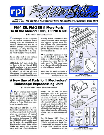
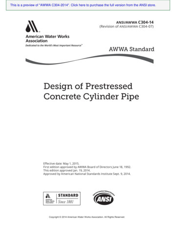
Assembly Instructions For Kit #FJ7375(To replace FJ783 Cylinder)1. Lubricate “O” Rings on Reducer and expander fittings and install reducer into supplied cylinderFJ7211. (Fig. 2)2. Install expander into reducer. (Fig. 2)3. Clean supplied adapter FJ7353-2. Back nut away from groove in fitting. Push washer back to end ofgroove.4. Push “O” ring back to washer. Lubricate “O” ring.5. Screw fitting into expander until the washer contacts fitting. (Fig. 2)6. Turn fitting counter clockwise less than one turn to lineup 1/4” pipe port (Fig 1). Hold fitting andtighten nut to 35-40 foot-pounds torque.7. There is a mix of restricted and nonrestricted cylinders serviced by kit #FJ7375. Lift performancecan be affected when nonrestricted and restricted cylinders are utilized on opposite sides of a lift.This kit contains adapters which have a restrictive feature built in to equalize cylinder rate of travel.Identification of cylinders are found as shown in figure 3. All FJ783 cylinders require restrictedadapter FJ7757. All FJ7211 cylinders supplied by Texas Hydraulics with a date code prior to 168Require a FJ7755 adapter. All FJ7211 cylinders supplied by Pacoma with a code prior to 3401529M96require a FJ7755 adapter. Check the code on all cylinders and assemble appropriate adapter into thecylinder not being replaced to insure all cylinders are restricted.Washer"O" RingNutFig 1ReducerGrooveAdapter1/4" Pipe PortExpanderCylinder Top3"-6"xxxxxxxxxxSupplier Name &Code IdentificationAreaFig 36Fig 2
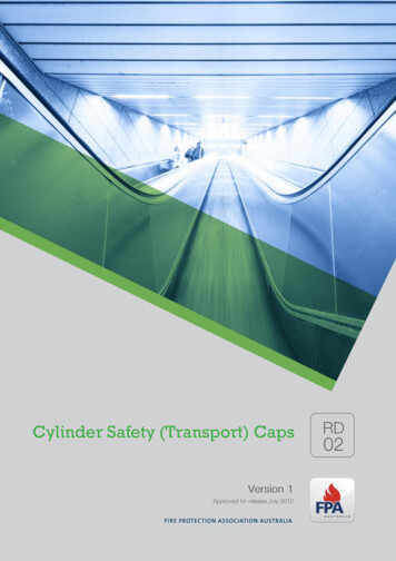
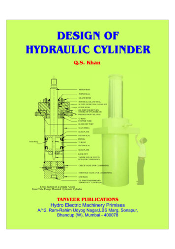
FJ592 Cylinder BleederReplacement KitInstallation InstructionsBLEEDERSCREWTOP OFCYLINDERReplace using the correct bleeder screw for themodel you have. Use the chart below to determinetype of cylinder used. Date codes for identifyingcan be found using the illustration below.3"-6"* DATECODEXXXXX* T 2 11 XXTEXASYEAR(1992)DAY OFMONTHMONTH(Nov.)Bleeder Screws For Texas Hydraulics CylindersPart No#. 32516 - Date code T211XX & after (Nov. 92)Consists of: Part No# 32326 Screw & Part No# 14525 O-Ring WasherBleeder Screws For Pacoma CylindersPart No#. 3443881 MI - All cylinders used the same screw.7
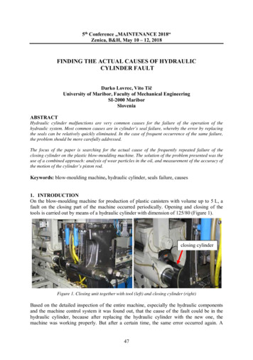
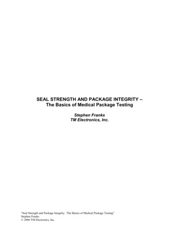
1181027639112345678910114AdapterHousingPiston RodBushing GuideFelt WiperFelt RingSealGuide RingRetainer WireSealBleeder Plug85
2-PostCylinderGuidePB 10-4-19
Cylinder Kit Identification Table2-Post Surface and Inground Lifts (SL Models)Lift ModelOriginal CylinderReplacement CylinderSeal kitSP70, SP74FJ76N/AFJ76-12SP80 Thru -3SP84 Thru -7FJ720N/AFJ720-12*FJ720-30SP55, SP80-4, SP80-5, SP848 Thru 11, SP84-16, SPO84,SPOA84, AR94, ARO94, MF***FJ783-12UKSP88, SPO88,SPOA88, SP98,SPO98, SPOA98, DCOA7,SPO82, AR98, 12UKWOA83, SP7, SP9, SPO7, SPO9Thru -200, SPOA7 Thru -200,SPOA9 Thru -200, TL07 83-12UKSPA7LC, 352-12MFSPOA7LC-400, SPOA10-500,SPO10-500N353N353**N342-12 (Pacoma)**N342-13 (Panni)SPOA7-300 Thru -400, SPOA9300 Thru -700, SPO9-300 Thru-700, SPOA10-300 Thru -700,TLO7-300 Thru -500SPO12-310 Thru -710N342N380**N342-12 (Pacoma)**N342-13 (Panni)SPOA7-300 Thru -700, SPOA9N382300 Thru -700, SPO9-300 ThruN343-700, SPOA10-300 Thru -700,TLO7-300 Thru -500, SPO12-310Thru -710 Extended rise 71” riseN347**N342-12 (Pacoma)**N342-13 (Panni)SPO10-400 Thru -500, SPOA10400 Thru -500.N346N346**N342-12 (Pacoma)**N342-13 (Panni)SPO10-500 Thru -700, SPOA10500 Thru -700.N380N380YN380EN380Y**N342-12 (Pacoma)**N342-13 (Panni)**N380Y-9180 (United Hyd)SPO12, SPO15, 0N310****N310KIT**FJ783-12TH**FJ783-12MF* FJ720-30 for both Best & Texas Hyd Cylinders** Rotary Lift had different cylinder suppliers for these cylinders. To identify the correct seal kit, observe to markings in the casing aprox. 6” from the bleeder screw. The word Pacoma indicates MF seal kit. The letters T, TX, TXT or no marking indicates theTH seal kit or United Hydraulics*** Kit contains both FJ783-12TH & FJ783-12MF seal kits**** N310 is an FJ7664 with adapters and flow control10
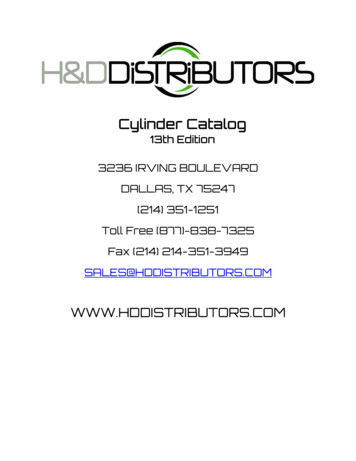
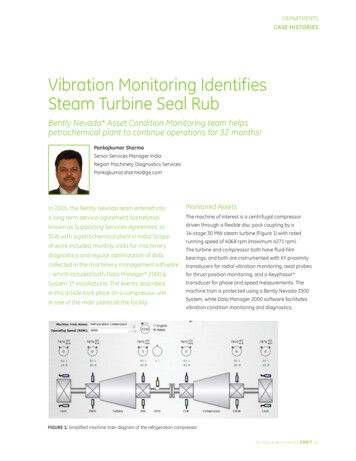
FJ720 CylinderFJ7375 Kit/FJ7211 Cylinder77" Retracted78 3/8" Retracted5 3/4" Retracted73 3/4" Extended21 3/8" Retracted89 3/8" Extended2 5/8"2 3/4"FJ7311 CylinderFJ7604 Cylinder75 3/8" Retracted79 15/16" Retracted6 11/16" Retracted74 11/16" Extended7 3/4" Retracted79 3/4" Extended1 3/8"1 7/8"11
N380e CylinderFJ7664/N310 CylinderFJ7606 Cylinder6 11/16Retracted74 11/16Extended3.353.0074" Retracted(Pacoma)48 1/4" Retracted116 1/4" Extended73.858" Retracted73 3/8" Retracted(Texas Hydraulics)6 11/16" Retracted74 11/16" Extended1 3/8"02-3/8FJ783 CylinderFJ76 CylinderN380y Cylinder170 Ref.(6.7)77" Retracted5 3/4" Retracted73 3/4" Extended2 5/8"1877 Ref.(73.9)75 1/4" Retracted12 1/2" Retracted80 1/2" Extended3 1/8"12
4-PostCylinderGuidePB 10-4-213
Cylinder Kit Identification Table4-Post LiftsLift ModelSM7992304S130093 (94" Stroke)S130095 (77" Stroke)FC5343 (Clevis)FC537 (Bracket)FC5342Replacement CylinderS130093S130095NLAFC537KITFC5797-1SM120, AR120, CWA120,SM121, AR121, QL4P, QLHVSM122, AR122, SMO123,ARO122, QL4P-100 QLHV-100,SM101-100SM123, AR123, SMO123,ARO123, SM12, AR12, QL4P200, QL12SM14, AR14,FC5342 (Clevis)FC542 97-1S130002S130002S130002S130002SMO14, ARO14S130156S130156SM180, SM181, SM18SM300, SM250, SM270, FLS25SM300, SM500, SM600FLS12, FLS1512000LRT (Mez)40000HDL, 50000HDL60000HDLScissor / Parallelogram 155992302992304992326FC8640-0604 (P1 Cyl.)40-0605 (P2 Cyl.)XS130008Z140039YNLA40-0604 (P1 Cyl.)40-0605 (P2 Cyl.)XS130008Z140039YFC86-12TH04L7173 (P1)04L7173 (P2)XS130138Z140039Y-12VSS7-000 & -010PS130004PS130004VSS7-001 & 8TH*PS100008MFSM90, AR90, CWA90, SM91,AR91SM101SC9iYA12Parking LiftSeal 61-12THFC5155-10992302SKAA992304SKAA* Rotary Lift had different cylinder suppliers for these cylinders. To identify the correct seal kit, observe to markings in thecasing. The word Pacoma indicates MF seal kit. The letters T, TX, TXT or no marking indicates the TH seal kit.**Hyko CylinderHow To Determine Cylinder Manufacturer:xxxxClevisDate/ID CodeNotes: Look all the way around the cylinder tube on the clevis or pressure port end for markings. Texas Hydraulic cylinders will be identified by a “TX” followed by a four digit date code stamped on thecylinder. In some cases the Rotary part number will be stamped above the date code. Pacoma cylinders will have “Pacoma” stamped on them.14
FC5343 Cylinder75-1/4" Retracted135-1/4" ExtendedFC537 Cylinder74-5/16" Retracted134-5/16" Extended73" Retracted133" Extended2-1/8"FC5155 Cylinder47-1/4" Retracted80-1/4" Extended1-1/2"FC5761 Cylinder83" Retracted143" Extended2-5/16"FC5225-15 Cylinder83" Retracted143" Extended5"15FC5797 Cylinder5"
FC5810-38 Cylinder78-5/16" Retracted138-5/16" ExtendedS130156 Cylinder80" Retracted146" Extended992326 Cylinder71.5" Retracted131.5" Extended2-1/8"82.75" Retracted154.75" ExtendedPS130004 Cylinder52.5" Retracted136.5" ExtendedS130002 Cylinder80" Retracted146" ExtendedVENDOR NUMBERS130002DATE CODE992302 Cylinder16
Low/Mid RiseCylinderGuidePB 10-4-317
Cylinder Kit Identification TableLow/Mid RiseLift ModelOriginal CylinderReplacement CylinderSeal kitPAL4, , PFX, MPFX, PSL6, VLX6,VLXS6, VL6, VLS6, VLD6FJ2248FJ2248*FJ2248-12TH*FJ294-3-12MFPFX-1, J2263*FJ2248-12TH*FJ294-3-12MFMR6, VM6, VMP6, VMP6A,VMR6FJ860FJ860FJ860-12THVLXS7, VLXS10992305992305**991513 (Texas)**992305SKAA (Arlington)**YG42-9180* Rotary Lift had different cylinder suppliers for these cylinders. To identify the correct seal kit, observe to markings in the casing. The word Pacoma indicates MF seal kit. The letters T, TX, TXT or no marking indicates the THseal kit.**Used three different cylinder Mfg. Look for markings on the cylinder. If no markings use YG642-9180 seal kit.BracketXXXXID/DateStampHow To Determine Cylinder Manufacturer: Look all the way around the cylinder tube on the clevis or pressure port end for markings. Texas Hydraulic cylinders will be identified by a “TX” followed by a four digit date code stamped onthe cylinder. In some cases the Rotary part number will be stamped above the date code. Pacoma cylinders will have “Pacoma” stamped on them. North Carolina cylinders are stamped “North Carolina”. Duke cylinders have a snap ring at the rod end.Seal Replacement:When replacing seals on lift models PAL4 and PAL5 use only seal kit FJ2248-12. All later PAL, MPAL, MPFX, andPFX models can use either seal kit FJ2248-12 or FJ294-3-12.18
FJ2248 CylinderFJ860 Cylinder25-5/8" Retracted43-5/8 " Extended43-5/8" Retracted79-5/8 " ExtendedFJ2263 Cylinder31-5/8" Retracted55-5/8 " Extended19
Smart LiftCylinderGuidePB 10-4-420
Lift ModelOriginal CylinderReplacement CylinderSeal kitSL19FJ7604FJ7604**FJ7604-12TH**FJ7604-12HPSL28, SL9, SL29 Thru 42N380N380N380**N342-12 (Pacoma)**N342-13 (Panni)SL29-400 Thru -800SL212-400 Thru 1000N367N367N342-12** Need to ID cylinder forcorrect kitFJ7604 CylinderFJ7664/N310 Cylinder74" Retracted(Pacoma)79 15/16" Retracted73 3/8" Retracted(Texas Hydraulics)7 3/4" Retracted79 3/4" Extended6 11/16" Retracted74 11/16" Extended1 7/8"1 3/8"N380e CylinderN380y Cylinder6 11/16Retracted74 11/16Extended170 Ref.(6.7)3.353.001877 Ref.(73.9)73.858" Retracted02-3/821
RevolutionCylinderGuidePB 10-4-522
Lift ModelOriginal CylinderReplacement CylinderSeal YG03-9180MCYMCY1-11MCY1-11N/AMCY-S, RXLDTYG09-9100YG09-9100YG09-9180RLR6A, RLR6F, 100G1YG07-9180RTP10992317992317YG32-9180RFP7P, RFP7NS130093 (94” Stroke)S130095 (77” 80Low Rise2-Post4-Post23
Rolling JackCylinderGuidePB 10-4-624
Cylinder Kit Identification TableRolling JackBridge ModelCapacityOriginal CylinderReplacement CylinderSeal 5050,000AB300007AB300007AP01515FC5642 CylinderFC5818-18 Cylinder9-5/8" Retracted15-5/16" Extended9-3/8" Retracted14-5/16" Extended2-7/8"3-3/32"25
FC570-2 CylinderFC5711-1 Cylinder10-1/8" Retracted15-5/16" Extended9" Retracted14-1/2" Extended4"2-7/16"FC5341-1 CylinderFC5185-20 Cylinder8-3/4" Retracted14-7/8" Extended9-5/8" Retracted15-5/16" Extended4-1/2"3"26
AccessoriesPB 10-4-727
Lift ModelOriginal CylinderReplacement CylinderSeal kitPortable Productivity JacksGUWSFF5, r Running Pit LiftGHUSSFFT20-143720999Suspended Pit LiftGHUSLP203720999Volkswagen Lift TableVAS6131AS2685-ZY1S2685-ZY128N/A
In-GroundCylinderGuidePB 10-4-829
ModelPlunderDiameterJackSerial #GasketPart #OriginalPackingGland #ReplacementOriginalPacking /Seal #ReplacementOriginalReplacement85, 86, 87, 88, 10 1/288B, 7, 7A8000 Thru8810H011 ThruH4276JK31NLANLANLAJK218NLAK8, K9, K109 1/2K0001 0G, 620G10 5/8G1139 ThruG129401 Thru 1138Non RequiredNon RequiredNLANLAJK218NLA8058 1/2B1 ThruB2690JG31NLANLANLAJK219NLA905, 912, 9159 1/2B1 ThruB2690JH31NLANLANLAJK219NLA1005, 1012,101510 5/8B1 ThruB2690JK31NLANLANLAJK219NLA5088 1/2C100 ThruC4241M1 ThruM2468JG31NLANLANLAJK220JK220KIT419, 509, 619, 9 1/2916, 1209,1509C100 ThruC4241M1 ThruM2468JH31NLAJH62NLAJK220JK220KIT420, ,510,620, 1016,1210, 151010 5/8C100 ThruC4241M1 ThruM2468JK31NLAJK62NLAJK220JK220KITFA9, FH9,RA9, RA19,RH9, RH19,FU9, FU19,RU19, FC99 1/2Ending inT1 ThruT9526JH31NLAJH62NLAJK220JK220KITFA10, FA20,FH10, FH20,FC10, RA10,RA20, RH10,RH10, RH20,T110, T210,T1012 (Frontjack only)10 5/8Ending inT1 ThruT9526JK31NLAJK62NLAJK220JK220KIT10FA, 10FH,20RH, 20RA,T110, T210,T1012 (Frontjack only)10 5/8Ending inV3 ThruV2880JK32NLAJK610NLAJK220JK220KITT112, T212,T1012 (Rearonly)12 5/8Preceded by JL31T or VNLANLANLAJL214NLA30
T112, T212,T212DS,T212LS,T1012,AT1012,AT1012DSE(Rear only)12 5/8Preceded by Non ReW or ending quiredin W5, W6,W7Non RequiredJ167J117JL215NLA12 5/8Ending inW8, JL123,JL124Non RequiredNon RequiredJL69J117JL215NLA12 5/8Ending inJL128 ThruJL133Non RequiredNon RequiredJL610J117JL217J11712 5/8Ending inJL134 andabove (except JL153)Non RequiredNon RequiredJL612JL612JL220JL220KITPreceded by Non ReW or ending quiredin W5, W6,W7Non RequiredJK69NLAJK221NLA10AF & HF,10 5/820AR & HR,31AR & HR,35AR & HR,T110A &H, 210A &H, T210DS,T210LS,T1010, FP10A& H, FP11A& H, FP45A,& H, FP12A& H, FP46A& H, FP36,VW5A & H,VF5A & H,DY10A & H,DRT10A & H,WABU10A& H, PF10A& H, PFV10A& H, AT70H& E, AT703E,AT704E,AT10210E,AT10210DSE,Rear jackonly ofAC60H &E, 810ML,810MLS,811ML,710MLS,Front jackonly ofAT1012E,AT1012DSE31
Ending inW8, JK123,JK124Non RequiredNon RequiredJK69NLAJK221NLAEnding inJK135 ThruJK157Non RequiredNon RequiredJK69J134JK223J134Ending inJK158 ThruJK1112Non RequiredNon RequiredJK69J134JK225J134Ending inJK1113 ThruJK1269Non RequiredNon RequiredJK69JK622JK227JK227KIT10 5/8FP46A & H,70C,P & Q,10210C,P &Q, R70C,P &Q, R10210C,P& Q, 703C,P & Q,R703C,P &Q, RU70C,P& Q,RU10210C,P& Q,RU703C,P& Q, 70HC,60HC, 52HCEnding inJK1303,JK1400 andaboveJK238JK238Non RequiredNon RequiredJK238JK238KIT28ML &8 1/2MLS, SE8,29ML &MLS, 811ML,78SF & MLEnding inJG118 ThruJG127Non RequiredNon RequiredJG67J136JK223J136FP8, VW4A& H, FP6,FP28A & H,FP7A & 5A,AP50H & E,AC60H & EFront jackonly8 1/2Ending inJG128 ThruJG148Non RequiredNon 20H,DTRP28H,WABU28H,WRP90,8 1/2Ending inJG149 ThruJG187 &JG190Non RequiredNon H,DTRP28H,RBU68H,AP50H & E,AC60H & E,52HC, 52C,52P, 710MLS(Front Jack)8 1/2Endingin JG188,JG189,JG191 andaboveJG37 O-RingJG37 O-RingNon RequiredNon RequiredJG227JG227KIT32
94, 948, 968 1/290001 - LA27SL, 27ML,78SF, 78ML7 1/2Ending in Y1Thru Y5Non RequiredNon RequiredNLANLAJG216NLAFP277 1/2Ending inJF15Non RequiredNon ront jackonly)7 1/2Ending inJF19 ThruJF122JF34 O-RingJF34 O-RingJF611JF611JF218JF218R12, FM12,FMRT1212 5/8JL1400 eJT11Non RequiredNon RequiredNon RequiredJ156J156-1LowerJ156-2LowerJ157 (Complete)J157-1 UpperJ157-2LowerMOD30Multi-StageJT14Non RequiredNon RequiredNon RequiredJ154J154J154J134 is a seal and gland assembly consisting of JK227 seal, JK622 gland, JX207 bleeder and new hard wear.This kit can be used to upgrade the JK225 and JK223 seals to the JK227 seal. This is required for a replacement of these older seals.J136 seal and gland assembly consists of JG220 seal, JG620 gland, JX207 bleeder and hardwareJ139 seal and gland assembly consists of JG220 seal, JG620 gland, JG36 spacer ring, JX207 bleeder and hardwareJ117 seal and gland assembly consists of JF220 seal, JF612 gland, JX207 bleeder and hardwareJ150 seal and gland assembly consists of JF218 seal, JF611 gland, JF34 o-ring, JX207 bleeder and hardwareJ156 seal and gland assembly for a JT11 jack, consisting of a J156-1 upper seal and gland assy, J156-2 lower seal and gland assy.J148 seal and gland assembly for High Pressure 10 5/8 Or Wash BayBearing and Gland Replacement KitsJG118 thru JG187 and JG190 use the JG629 bearing and gland replacement kit. It is required to use a JG230 mandrel for installation.The mandrel is reusableJK1113 thru JK1299 and use the JK629 bearing and gland replacement kit. It is required to use a Jk244 mandrel for installation.The mandrel is reusableTOOLSJK244 10 5/8” mandrelJG230 8 1/2” mandrelPR810134 12 1/2” mandrelIR06200010BK MOD30 JT14 clamp ring tool kit jackPR080191BK MOD30 JT11 Spanner wrench33
HD SurfacePB 10-4-934
Lift ModelOriginal CylinderReplacement CylinderSeal 13003334/27F (6”Cyl.Flush)AP00741AP00741AP0070445/35S (6”Cyl.Surface)AP00642AP00642AP0070450/25F (7”Cyl.Flush)AP00742AP00742AP0069650/25S (7”Cyl.Surface)AP00643AP00643AP0069650/26S (7”Cyl.Surface)AP00643AP00643AP0069650/32S (6”Cyl.Surface)AP00642AP00642AP0070450/48S (7”Cyl.Surface)AP00950AP00950AP006965 1/2” Cyl. Surface610-307-00591-01-1580AP018086” Cyl. Surface/FlushAP01397AP01397AP007047” Cyl. SurfaceAP01398AP01398AP006967” Cyl. Flush705-305-00591-01-1630AP006965 1/2” Cyl. SurfaceAP02668AP02668AP018086” Cyl. SurfaceAP026262005-13-312-00AP027466” Cyl. FlushAP026502005-14-312-00AP027467” Cyl. Surface in Res.AP01398AP01398AP006967” Cyl. SurfaceAP025982005-17-312-00AP006967” Cyl. FlushAP026822005-18-312-00AP006965 1/2” Cyl. SurfaceAP02668AP02668AP018086” Cyl. SurfaceAP026262005-13-312-00AP027466” Cyl. FlushAP026502005-14-312-00AP027467” Cyl. SurfaceAP025982005-17-312-00AP006967” Cyl. FlushAP026822005-18-312-00AP00696Movable ColumnParallelogramClassicGen 21995- 2001(April)Gen 32001(May)-2008Gen 42009-Current35
Rotary World Headquarters2700 Lanier DriveMadison, IN 47250, USAwww.rotarylift.comNorth America Contact InformationWorld Wide Contact InformationTech. Support: p 800.445.5438World Headquarters/USA: 1.812.273.1622f 800.578.5438Canada: 1.905.812.9920e userlink@rotarylift.comEuropean Headquarters/Germany: 49.771.9233.0Sales: p 800.640.5438United Kingdom: 44.178.747.7711f 800.578.5438Australasia: 60.3.7660.0285e userlink@rotarylift.comLatin America / Caribbean: 54.3488.431.608 Rotary , Printed in U.S.A., All RightsMiddle East / Northern Africa: 49.771.9233.0Reserved. Unless otherwise indicated,ROTARY, DOVER and all other trademarks are property of Dover Corporation and its affiliates.
Bleed air from both cylinders. 8) Fully lower lift. 9) Check and add fluid as necessary. 10) Raise lift to full rise and check for leaks. 11) Tag lift back in service. 4 SP84, SPOA84, SP94, Series Lifts Cylinder Removal Procedure 1) Raise the lift about 2’-0”. Open manual bleeder in top of both cylinder